Tuthill M-D Pneumatics 3204 Operator's Manual
Mechanical c-flange vacuum boosters
Hide thumbs
Also See for M-D Pneumatics 3204:
Table of Contents
Advertisement
WARNING: Do Not Operate Before Reading Manual
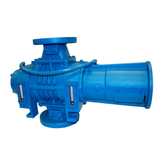
Mechanical C-Flange Vacuum Boosters
OPERATOR'S MANUAL
Models
3204
4009
5509
3206
4012
5511
3210
5507
5514
91/93 Series - Horizontal Flow
90/92 Series - Vertical Flow
Tuthill Vacuum & Blower Systems
M-D Pneumatics
Mechanical Vacuum Boosters
5518
7013
7026
5524
7017
7010
7021
tuthillvacuumblower.com
™
Manual 2000 0811 ENG
800.825.6937
Advertisement
Table of Contents

Related Manuals for Tuthill M-D Pneumatics 3204


Summary of Contents for Tuthill M-D Pneumatics 3204
- Page 1 Mechanical C-Flange Vacuum Boosters OPERATOR’S MANUAL Models 3204 4009 5509 5518 7013 7026 3206 4012 5511 5524 7017 3210 5507 5514 7010 7021 91/93 Series - Horizontal Flow 90/92 Series - Vertical Flow Tuthill Vacuum & Blower Systems tuthillvacuumblower.com 800.825.6937...
-
Page 2: Table Of Contents
TABLE OF CONTENTS SECTION PAGE 1. INTRODUCTION 1.1 APPLICABLE DOCUMENTATION 1.2 SCOPE OF MANUAL 2. CONVENTIONS AND DATA PLATE 2.1 GRAPHIC CONVENTIONS IN MANUAL 2.2 DATA PLATE 3. LIFTING 4. DESCRIPTION 4.1 FLOW BY DIRECTION AND ROTATION 4.2 SPECIFICATIONS 5. INSTALLATION 5.1 GENERAL 5.1.1 LOCATION 5.1.2 FOUNDATION... -
Page 3: Introduction
• EN 1012-2:1996 – Compressors and vacuum pumps - Safety Requirements - Part 2: Vacuum Pumps 1.2 SCOPE OF MANUAL The scope of this manual and the Declaration of Conformity includes the following components offered, as a complete assembly, by Tuthill Vacuum & Blower Systems: • Vacuum booster with integral C-face flange • Coupling •... -
Page 4: Conventions And Data Plate
2.2 DATA PLATE MAWP YEAR Tuthill Vacuum & Blower Systems MAX RPM 4840 West Kearney Street Springfield, Missouri USA 65803 READ INSTRUCTION MANUAL BEFORE OPERATION OR BODILY HARM MAY RESULT... -
Page 5: Lifting
Refer to diagrams in this manual for proper rotation and orientation in inlet and discharge. Tuthill Vacuum & Blower Systems model 3200, 4000, 5500 and 7000 Series C-Flange mechanical vacuum boosters are positive displacement type units, whose pumping capacity is determined by size, operating speed, and differential pressure conditions. -
Page 6: Flow By Direction And Rotation
Consult your Tuthill Vacuum & Blower Systems sales professional if questions arise. DANGER As with any equipment with rotating elements, the booster will over time become a source of media leaks and a source of ignition. -
Page 7: Specifications
VERTICAL FLOW HORIZONTAL FLOW INTAKE DISCHARGE INTAKE DISCHARGE DISCHARGE INTAKE DISCHARGE INTAKE TOP DRIVE TOP DRIVE CW ROTATION CCW ROTATION INTAKE DISCHARGE DISCHARGE INTAKE INTAKE DISCHARGE DISCHARGE INTAKE RIGHT DRIVE RIGHT DRIVE LEFT DRIVE LEFT DRIVE CW ROTATION CCW ROTATION CW ROTATION CCW ROTATION BOTTOM DRIVE... -
Page 8: Installation
Specially ordered blowers with nonstandard construction, or with rotor end clearances greater than shown within the Assembly Clearances table, will not have the operating limits specified here. Contact your Tuthill Vacuum & Blower Systems sales representative for specific information. NOTE Special attention must be paid when a vacuum booster has a higher than standard ambient suction temperature. - Page 9 WARNING The bare shaft booster can generate excessive noise. Methods to reduce the noise levels by installing inlet and outlet silencers will be required. Even with inlet and outlet silencers, hearing protection will be required. WARNING Customers are warned to provide adequate protection, warning and safety equipment necessary to protect personnel against hazards in the installation and operation of this equipment in the system or facility.
-
Page 10: Location
(See the Motor Drives section for more information.) Boosters from Tuthill Vacuum & Blower Systems are internally and externally treated after factory assembly and testing to protect against rusting in normal atmospheric conditions prior to installation. The maximum period of internal protection is considered to be up to 6 months under average conditions, provided closing plugs and seals are not removed. -
Page 11: Soft Foot
Figure 3 - Illustrations of Soft Foot 5.2 SAFETY Tuthill Vacuum & Blower Systems recommends the use of relief valves to protect against excessive pressure or vacuum conditions. These valves should be tested at initial start-up to be sure they are properly adjusted to relieve at or below the maximum pressure differential rating of the booster. -
Page 12: Lubrication
5.3 LUBRICATION Every booster from Tuthill Vacuum & Blower Systems is factory tested, oil drained and shipped dry to its installation point. Both independent oil reservoirs must be filled to the proper level before operation. Oil reservoirs are under vacuum. -
Page 13: Filling Procedure
NOTE Refer to Table 1 for oil capacities. 5.3.1 FILLING PROCEDURE See Figure 4. Recommended lubricants are shown on page 42. 1. Remove fill plugs or breathers from both gear end and drive end plates. 2. SLOWLY pour oil through fill until oil appears in the oil sight glass. Bring oil level to center of sight glass. 3. -
Page 14: Hazards Associated With Breakdown Or Ignition Of Lubrication
package. An indicator of the breakdown of a lubricant is the increase in the TAN (Total Acid Number), and a change in the base viscosity of ten percent. Several things are happening as the lubricant goes through the unit. First, it is absorbing frictional energy in the form of heat. -
Page 15: Blockage Or Restriction
The partly water-cooled versions (92/93) have cooling INTERCONNECTING water to the seal adapter housing only. The cooling LINES coils and interconnecting water line are omitted and the interconnecting line leading from the seal adapter housing is led to the drain. The air-cooled configuration requires no cooling water. -
Page 16: Cooling Water Connections
5.6 COOLING WATER CONNECTIONS 3200/4000/5000 SERIES 7000 SERIES 1/8” NPT 1/2” NPT 1/2” NPT 1/2” NPT 1/2” NPT 1/8” NPT WATER INLET WATER INLET WATER INLET WATER OUTLET WATER OUTLET WATER OUTLET SIDE BOTTOM TYPICAL PORT LOCATIONS ARE SHOWN HERE. Figure 6 - Water Cooling Connections 5.7 COOLING WATER SPECIFICATIONS NOTE... -
Page 17: Motor And Electrical Connections
Proper gap between coupling halves must be established according to coupling manufacturers instructions with the motor armature. This will minimize the change for end thrust on the booster shaft. All direct coupled base mounted units must be re-aligned and greased after field installation. 5.10 MOTOR AND ELECTRICAL CONNECTIONS WARNING The motor and connections shall be protected to assure that product and... -
Page 18: Operation
NOTE Be sure not to compress the rubber sleeves or the spider between the couplings or hub halfs. Compression could result in damage or failure. Consult manufacturer’s instructions for approximate gaps between coupling or hubs. 6. OPERATION 6.1 GENERAL DANGER The booster is not intended to be used with explosive products or in explosive environments. -
Page 19: Start-Up Checklist
6.2 START-UP CHECKLIST We recommend that these startup procedures be followed in sequence and checked off ( ) in the boxes provided in any of the following cases: • During initial installation • After maintenance work has been performed • After any shutdown period •... -
Page 20: Stopping
WARNING Physical harm may occur if human body parts are in contact or exposed to the process vacuum. Assure that all connections are protected from human contact. WARNING If rated vacuum or pressure levels are exceeded, process fluids will migrate to other parts of the booster and system. -
Page 21: Operation
However, due to the wide variations in mineral content, pH, and chemical content of water that can be injected, Tuthill Vacuum & Blower Systems cannot be responsible for damage which may result should this build-up occur. Units should be inspected regularly to determine any problems. -
Page 22: Recommended Shutdown Procedure To Minimize Risk Of Freezing Or Corrosion
6.8 RECOMMENDED SHUTDOWN PROCEDURE TO MINIMIZE RISK OF FREEZING OR CORROSION When high humidity or moisture is present in an air piping system, condensation of water can occur after the booster is shut down and the booster begins to cool. This creates an environment favorable to corrosion of the iron internal surfaces, or in cold weather, the formation of ice. -
Page 23: Regular Maintenance
DANGER The booster and connecting piping shall be regularly inspected to assure that process gases are not vented such that a hazard is created. The booster shall also be regularly inspected to assure that the booster and the drive components do not create a source of ignition. CAUTION The electrical service must be isolated and de-energized prior to maintenance. -
Page 24: Spare Parts
Personnel should have a good background of mechanical experience and be thoroughly familiar with the procedures outlined in this manual. Major repairs not covered in this book should be referred to the nearest Tuthill Vacuum & Blower Systems service representative. -
Page 25: Long Term Storage
7.5 LONG TERM STORAGE Any time the booster will be stored for an extended period of time, you should take make sure that it is protected from corrosion by following these steps: 1. Spray the interior (lobes, housing and end plates) with rust preventative. This should be repeated as conditions dictate and at least on a yearly basis. - Page 26 7. Mark housing, end plates, rotors, and gears before proceeding with disassembly. There are two methods which can be used to disassemble the rest of the unit. Method “A” requires an arbor press and method “B” requires the use of bar or yoke pullers. See puller drawing (T29603) on page 44. 8.
- Page 27 Be sure they are in place. It is recommended that the gear end rotor shaft bearings be purchased from Tuthill Vacuum and Blower Systems, as they are specially ground to locate the rotors with correct end clearance relative to the gear end plate.
- Page 28 6. Lubricate shafts and press the double row ball bearings [9] onto rotor shafts and into end plate bores. NOTE These bearings have been flush ground at the factory. The inner race will have a black dot etched on the surface. This dot must be up and visible when bearings are installed.
- Page 29 17. Install spacer [67] on each shaft. Install oil slinger [21] on lower rotor, (either shaft on vertical flow units) spacer [57] on opposite shaft, washers [25], and screws [29]. Lay assembly down with drive on left for timing. 8.2.5 ADJUSTING ROTOR INTERLOBE CLEARANCE: 18.
-
Page 30: Model 4000C And 5500C Series Disassembly And Reassembly
9. MODEL 4000C AND 5500C SERIES DISASSEMBLY AND REASSEMBLY WARNING Before performing any repair or replacement, disconnect and lock out power. With proper maintenance and lubrication, normal life expectancy for gears, bearings, and seals can be achieved. However, over a period of time these parts must be replaced to maintain the efficiency of your booster. - Page 31 Be sure they are in place. It is recommended that the gear end rotor shaft bearings be purchased from Tuthill Vacuum and Blower Systems, as they are specially ground to locate the rotors with correct end clearance relative to the gear end plate.
- Page 32 9.2.2 GEAR END ASSEMBLY 3. Stand rotors [1] on arbor press table with gear end shafts up. See Figure 13. Two keyways should DRIVE point in the same direction, to the right. 4. Carefully install gear end plate over rotor shafts. Keyways Facing Same...
- Page 33 9.2.4 HOUSING AND FREE END ASSEMBLY 11. Place a small bead of sealer around the periphery of the end plate, encircling each bolt hole. Install rotor housing [3] and secure with four screws evenly spaced. 12. Check clearance between the end of lobes and the housing using a flat bar and feeler gauges or a depth micrometer.
- Page 34 right side reading is higher than the left side, remove shim. If the right side reading is lower, add shim. When removing gear shell from driven gear, it is not necessary to remove gear lock nut. Make sure bolt locks are in place because the dowel pins must come off with the gear shell. 19.
-
Page 35: Model 7000C Series Disassembly And Reassembly
10. MODEL 7000C SERIES DISASSEMBLY AND REASSEMBLY WARNING Before performing any repair or replacement, disconnect and lock out power. With proper maintenance and lubrication, normal life expectancy for gears, bearings, and seals can be achieved. However, over a period of time these parts must be repaired or replaced to maintain the efficiency of your booster. - Page 36 Be sure they are in place. An O-ring lubricant should be used on all O-rings. It is recommended that the gear end rotor shaft bearings be purchased from Tuthill Vacuum & Blower Systems, as they are specially ground to locate the rotors with correct end clearance relative to the gear end plate.
- Page 37 10.2.2 GEAR END ASSEMBLY 3. Place free end plate on suitable blocking with rotor DRIVE side up. Stand rotors (1) into each bore with gear end shafts up and keyways facing in the direction shown in Figure 18 to the right. 4.
- Page 38 11. Put sealer on rotor housing, same as above. Install free end plate and secure in same manner. 12. Install seal mating rings as was done in Step 4. Install one bearing spacer (57) on each shaft. Lubricate shafts and install roller bearing with inner race flange outward. See Figure 19. Install second bearing spacer (57) on each shaft.
- Page 39 10.3 INSTRUCTIONS FOR CONVERTING DRIVES 10.3.1 BOTTOM DRIVE UNITS If the sight glasses are on the right side as you face the drive shaft you can make a right drive unit by changing mounting feet, lift lugs, sight glasses and magnetic drain plugs. If the sight glasses are on the left you can make a left drive unit by changing the same items above.
-
Page 40: Troubleshooting
11. TROUBLESHOOTING Although Tuthill Vacuum & Blower Systems boosters are well designed and manufactured, problems may occur due to normal wear and the need for readjustment. The chart below lists symptoms that may occur along with probable causes and remedies. -
Page 41: Assembly Clearances
12. ASSEMBLY CLEARANCES Values are shown in inches and millimeters. GEAR END FREE END INTERLOBE TIP-PORT MODEL TIP-DOWEL .003 - .005 .006 - .010 .003 - .007 .006 - .010 3204 .08 - .13 .15 - .25 .08 - .18 15 - .25 .003 - .005 .012 - .017... -
Page 42: Recommended Lubricants
Blowers used in hydrogen service should use only PneuLube synthetic oil. Tuthill Vacuum & Blower Systems cannot accept responsibility for damage to seals, O-rings and gaskets caused by use of synthetic lubricants not recommended by Tuthill Vacuum and Blower Systems. - Page 43 NOTES:...
-
Page 44: Tool Drawings
15. TOOL DRAWINGS FIGURE 21 — 3200C SEAL PRESSING TOOL (T32018-2) FIGURE 20 — 3200C SEAL PRESSING TOOL (T32018-1) 1.50 38.1 3.25 18.8 82.6 12.7 Ø 2.50 MIN R Ø 2.044 ± .001 63.5 51.90 ± .03 Ø 1.872 ± .001 Ø... - Page 45 FIGURE 25 — 7000C LAB SEAL PRESSING TOOL FIGURE 26 — 7000C MECHANICAL & LIP SEAL TOOL 4.62 117.35 4.62 ± 0.0025 70.9041 0.9025 ± 0.0635 ± 0.0025 22.9235 ± 0.0635 Ø 4.719 3.40 Ø 4.240 Ø 3.75 Ø ± 0.001 2.25 86.36 107.696...
-
Page 46: Parts Lists And Assembly Drawings
PARTS LIST FOR MODEL 3200C SERIES ITEM ITEM DESCRIPTION 90/91 92/93 DESCRIPTION 90/91 92/93 ROTOR SPACER HOUSING SIGHT GLASS MECHANICAL SEAL END PLATE DRIVE END COVER OIL RETAINER — FREE END COVER PIPE PLUG TIMING GEAR SET SEAL ADAPTER HOUSING BEARING, DRIVE END O-RING SCREW... - Page 47 PARTS LIST FOR MODEL 4000C SERIES ITEM ITEM DESCRIPTION 90/91 92/93 DESCRIPTION 90/91 92/93 ROTOR SIGHT GLASS 0 / 1 0 / 1 HOUSING MECHANICAL SEAL END PLATE OIL RETAINER — DRIVE END COVER PIPE PLUG FREE END COVER SEAL ADAPTER HOUSING TIMING GEAR SET O-RING BEARING, DRIVE END...
- Page 48 PARTS LIST FOR MODEL 5500C SERIES ITEM ITEM DESCRIPTION 90/91 92/93 DESCRIPTION 90/91 92/93 ROTOR SIGHT GLASS 0 / 1 0 / 1 HOUSING MECHANICAL SEAL END PLATE OIL RETAINER — DRIVE END COVER WASHER 0 / 1 0 / 1 FREE END COVER PIPE PLUG TIMING GEAR SET...
- Page 49 PARTS LIST FOR MODEL 7000C SERIES ITEM ITEM DESCRIPTION 90/91 DESCRIPTION 90/91 ROTOR O-RING HOUSING WASHER END PLATE PIPE PLUG DRIVE END COVER LOCKING RING FREE END COVER SET SCREW TIMING GEAR SET LIP SEAL BEARING, DRIVE END O-RING BEARING, FREE END CAP SCREW LIP SEAL COOLING COILS...
- Page 67 DRIVE COUPLING (U.S. CUSTOMARY) – 31718 (–) SHAFT DIAMETER WOOD'S SURE-FLEX COUPLING COUPLING SLEEVE OVER THRU TYPE S THIRD CONSTRUCTION .438 .562 .125 X .125 DIGIT OF TYPE AND MATERIAL .562 .875 .188 X .188 DASH NO. DASH NO. EQUALS COUPLING SIZE, TYPE SLEEVE .875 1.250 .250 X .250...
- Page 68 NOTES:...
-
Page 69: Declaration Of Conformity
MODEL 3200(M)C, 4000(M)C, 5500(M)C AND 7000(M)C 90/92 SERIES – VERTICAL FLOW 91/93 SERIES – HORIZONTAL FLOW The person authorized to compile the technical file is Xavier Lambert, Tuthill Corporation, Parc Industriel Wavre Nord-Avenue Vesale 30, B-1300 Wavre Belgium. David Schardt VP of Engineering &... -
Page 70: Warranty - Blower Products
WARRANTY – BLOWER PRODUCTS Subject to the terms and conditions hereinafter set forth and set forth in General Terms of Sale, Tuthill Vacuum & Blower Systems (the Seller) warrants products and parts of its manufacture, when shipped, and its work (including installation and start-up) when performed, will be of good quality and will be free from defects in material and workmanship. -
Page 71: Operating Data Form / Product Registration
NOTES: IMPORTANT All blowers manufactured by Tuthill Vacuum & Blower Systems are date coded at time of shipment. In order to assure you of the full benefits of the product warranty, please complete, tear out and return the product registration card, or register online at tuthillvacuumblower.com. - Page 72 For Service & Repair, Technical Support, or Product Sales contact: VACUUM & BLOWER SYSTEMS Tuthill Vacuum & Blower Systems TUTHILL CORPORATION 4840 West Kearney Street Springfield, Missouri USA 65803-8702 O 417.865.8715 800.825.6937 F 417.865.2950 tuthillvacuumblower.com Manual 2000 0811 ENG...
Need help?
Do you have a question about the M-D Pneumatics 3204 and is the answer not in the manual?
Questions and answers