Table of Contents
Advertisement
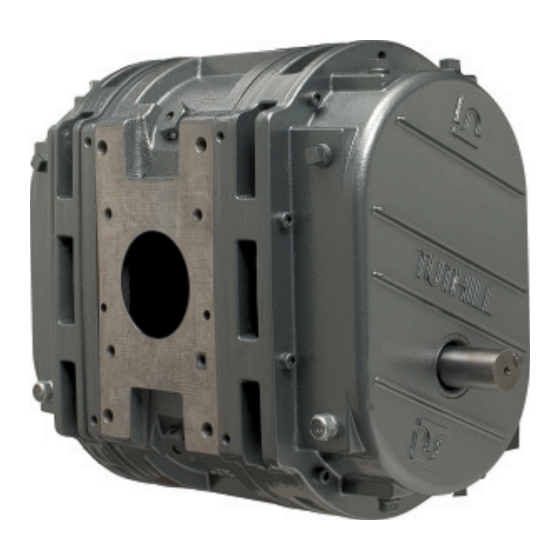
M-D Pneumatics
™
Rotary Positive Displacement Truck Blower
Manual 2020 0217 ENG
WARNING: Do Not Operate Before Reading Manual
T850 / T1050 - Standard Weight
OPERATOR'S MANUAL
Copyright © 2017 Tuthill Vacuum & Blower Systems
All rights reserved. Product information and specifi cations subject to change.
Tuthill Vacuum & Blower Systems
tuthillvacuumblower.com
800.825.6937
Advertisement
Table of Contents


Need help?
Do you have a question about the T850 and is the answer not in the manual?
Questions and answers
does it matter the rotation of the blower?
Yes, the rotation of the Tuthill T850 blower matters. It must rotate in the correct direction as indicated by an arrow to ensure proper operation.
This answer is automatically generated