Table of Contents
Advertisement
Quick Links
WARNING: Do Not Operate Before Reading Manual
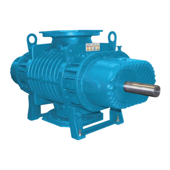
PD Plus
OPERATOR'S MANUAL
Models
7010
7021
7013
7026
7017
Horizontal Air Flow
Vertical Air Flow
Horizontal Flow, Single Envelope Gastight
Vertical Flow, Single Envelope Gastight
Horizontal Flow, Double Envelope Gastight
Vertical Flow, Double Envelope Gastight
All rights reserved. Product information and specifications subject to change.
Tuthill Vacuum & Blower Systems
Copyright © 2018 Tuthill Vacuum & Blower Systems
tuthillvacuumblower.com
M-D Pneumatics
™
Rotary Positive Displacement Blower
Manual 2007 Rev B p/n 2007
800.825.6937
Advertisement
Table of Contents

Related Manuals for Tuthill PD Plus


Summary of Contents for Tuthill PD Plus
- Page 1 Horizontal Flow, Single Envelope Gastight Vertical Flow, Single Envelope Gastight Horizontal Flow, Double Envelope Gastight Vertical Flow, Double Envelope Gastight Copyright © 2018 Tuthill Vacuum & Blower Systems All rights reserved. Product information and specifications subject to change. Tuthill Vacuum & Blower Systems tuthillvacuumblower.com...
- Page 2 No part of this publication may be reproduced or used in any form by any means – graphic, electronic or mechanical, including photocopying, recording, taping or information storage and retrieval systems – without the written permission of Tuthill Vacuum & Blower Systems. Copyright © 2018 Tuthill Vacuum & Blower Systems...
-
Page 3: Table Of Contents
Table of Contents Introduction .................. 1 Applicable Documentation ..............1 Scope of Manual ................... 1 Conventions and Data Plate ............2 Graphic Conventions in this Manual ............. 2 Data Plate ....................3 Lifting .................... 5 Description ................... 6 Flow by Direction................... 7 Specifi... - Page 4 Table of Contents Hazards Associated With Breakdown or Ignition of Lubrication ................17 Lubrication (Splash) ..............17 Lubrication (Integral Pressure) ..........18 Oil Filter on Integral Lube Blowers ........... 18 Integral Lube Oil Pressure Adjustment ........18 Piping Connections ................18 Hazards Associated With Hazardous Process Fluids ....
- Page 5 Table of Contents Maintenance ................28 General ....................28 Regular Maintenance ................28 Spare Parts ..................29 Factory Service and Repair ..............29 Long-Term Storage ................30 Disassembly and Reassembly ..........31 Disassembly of Blower ............... 31 Assembly of 7000 Blower ..............33 Preparation of End Plates for Assembly ........
- Page 6 Table of Contents Manual 2007 Rev B p/n 2007...
-
Page 7: Introduction
Compressors sure to protect it from weather and corrosion. SCOPE OF MANUAL PD PLUS blowers are built to exacting standards and, if properly installed and maintained, will provide many years of reliable service. Read The scope of this manual and the Declaration of... -
Page 8: Conventions And Data Plate
CONVENTIONS AND DATA PLATE GRAPHIC CONVENTIONS IN THIS OTE: Indicates a procedure, practice, or condition that should be followed in MANUAL order for the equipment to function in the manner intended. This manual is the result of a risk assessment according to the applicable documents referenced in “Applicable Documentation”... -
Page 9: Data Plate
Conventions and Data Plate DATA PLATE MAWP YEAR Tuthill Vacuum & Blower Systems MAX RPM 4840 West Kearney Street Springfield, Missouri USA 65803 READ INSTRUCTION MANUAL BEFORE OPERATION OR BODILY HARM MAY RESULT WARNING WARNING CAUTION CAUTION Do not operate without... - Page 10 Conventions and Data Plate MODEL NUMBER: The specifi c model of the blower SERIAL NUMBER: Unique to each blower YEAR: Year of manufacture MAWP: Maximum Allowable Working Pressure The standard MAWP is per Table 4-3 – Maximum Operating Limits on page 9.
-
Page 11: Lifting
LIFTING WARNING The blower must be handled using an appropriate device such as a fork truck or appropriate lifting device. See Table 4-1 and Table 4-2 on page 8 for approximate weights. Care should be taken to assure blower does not over-turn during handling and installation. -
Page 12: Description
Consult a Tuthill Vacuum & Blower Systems sales discharge port or upstream of the blower inlet port. professional if questions arise. -
Page 13: Flow By Direction
Description INLET INLET INLET DISCHARGE DISCHARGE DISCHARGE Figure 4-1 – General Operation Principle FLOW BY DIRECTION WARNING Refer to diagrams in this manual for proper rotation and orientation in inlet and discharge. VERTICAL FLOW HORIZONTAL FLOW INTAKE DISCHARGE INTAKE DISCHARGE DISCHARGE INTAKE DISCHARGE... -
Page 14: Specifi Cations
Description SPECIFICATIONS APPROXIMATE OIL APPROXIMATE WEIGHT CAPACITY MAXIMUM MODEL PORT SIZE VERTICAL HORIZONTAL VERTICAL HORIZONTAL FLOW FLOW FLOW FLOW 7010 8.0 qt (7.5 L) 5.0 qt (4.75 L) 6 in. (150 mm) 3,000 – 1,120 lb (510 kg) 7013 8.0 qt (7.5 L) 5.0 qt (4.75 L) 8 in. - Page 15 Assembly Clearances on page 39, will not have the operating limits specifi ed here. Contact your WARNING Tuthill Vacuum & Blower Systems sales representative for specifi c information. The maximum allowable working pressure (MAWP) is based on the absolute pressure of the blower housing and is NOT the maximum allowable pressure differential.
-
Page 16: Installation
INSTALLATION GENERAL WARNING Customers are warned to provide adequate protection, warning and safety equipment DANGER necessary to protect personnel against hazards in the installation and operation of The blower is not intended to be used this equipment in the system or facility. with explosive products or in explosive environments. - Page 17 Installation base. Shims may be needed for alignment. Loosen WARNING the foot hold-down screws to check foot contact with the mounting surface. Mount the base on a Upon completion of the installation, and solid foundation or heavy fl ooring, using shims as before applying power, rotate the drive necessary at bolting points to prevent warping the shaft by hand.
-
Page 18: Location
See Motor Drives on page 20 for more information. To minimize maintenance, supply the blower with Blowers from Tuthill Vacuum & Blower Systems the cleanest air possible. The air must not contain are internally and externally treated after factory any fl... -
Page 19: Soft Foot
Soft Foot Soft foot is a condition in which one of the blower Tuthill Vacuum & Blower Systems recommends feet does not sit fl at on the base. Soft foot is the use of relief valves to protect against excessive usually due to irregularities in the surface to which pressure or vacuum conditions. -
Page 20: Lubrication
Installation LUBRICATION DANGER Every booster from Tuthill Vacuum & Blower Assure that properly sized vacuum breaks/ Systems is factory-tested, oil-drained, and shipped relief valves are used on the inlet side of dry to its installation point. Fill both independent oil the blower. -
Page 21: Filling Procedure
Installation Filling Procedure Assure oil is compatible with copper/yellow See Figure 5-3 and Figure 5-4. metals (if equipped with cooling coils). See Recommended Lubricants on page 41 for suggested lubricants. 1. Remove the fi ll plugs or breathers from both gear end and drive end plates. - Page 22 Installation Figure 5-4 – Locations of Oil Fill, Drain, Level Gauges, and Cooling Connections on Blowers with Integral Lubrication Manual 2007 Rev B p/n 2007...
-
Page 23: Frequently Asked Questions Regarding Lubrication
Installation Frequently Asked Questions Regarding Hazards Associated With Breakdown or Lubrication Ignition of Lubrication What is the functional detriment if the “wrong oil” is used? DANGER The lubricant is selected based on bearing There is a risk associated speed, gear speed, and operating temperature. with the lubrication media If the lubricant is too light, it increases wear by breaking down and resulting... -
Page 24: Lubrication (Integral Pressure)
Pipe loading on the blower should be The oil fi lters (P/N 70248) are available from negligible as pipe loading can cause Tuthill Vacuum and Blower Systems in Springfi eld, Missouri, or from any authorized distributor or distortion of the blower. Use proper supports service center. -
Page 25: Hazards Associated With Hazardous Process Fluids
13th position of the complete blower model number. Blockage or Restriction Tuthill Vacuum & Blower Systems recommends water cooling for blowers in applications where the blower operates with discharge temperatures of WARNING 250°F (120°C) for periods of 4 hours or more per... -
Page 26: Cooling Water Connections And Specifi Cations - Cooling Coils (Optional)
Installation COOLING WATER CONNECTIONS Coupling halves must correctly fi t the blower and drive shafts so that only light tapping is required to AND SPECIFICATIONS — COOLING install each half. The two shafts must be accurately aligned, A direct-coupled blower and motor must be COILS (OPTIONAL) aligned with the two shafts not having more than 0.005 in. -
Page 27: Setting V-Belt Tension
Installation A tight or driving fi t will force the drive shaft out of If the drive shaft does not rotate freely: its normal position and cause internal damage. A • Look for uneven mounting, piping strain, loose fi t will result in shaft damage or breaking. excessive belt tension, or coupling misalignment. -
Page 28: Motor And Electrical Connections
Installation Motor and Electrical Connections WARNING The motor and connections shall be protected to assure that product and environmental condensation does not come in contact with the electrical connections. It is the responsibility of the installer to assure that the motor is in compliance with the latest edition of IEC 60204-1 and all electrical connections are performed per IEC 60204-1. -
Page 29: Operation
OPERATION GENERAL Before starting the blower for the fi rst time under power, recheck the installation thoroughly to reduce the likelihood of diffi culties. Use the following checklist as a guide, but also consider DANGER any other special conditions in your installation. The blower is not intended to be used with 1. -
Page 30: Start-Up Checklist
Operation Carry out initial operation under “no load” steady. These checks may be particularly important conditions by opening all valves and venting if the blower is part of a process system where the discharge to atmosphere, if possible. Then, conditions may vary. At the fi rst opportunity, stop start motor briefl... -
Page 31: Operating
Operation OPERATING CAUTION The upper temperature limit for blower operation Use of a thermowell insulates the is 400°F (205°C), measured in the exhaust gas thermocouple. Invalid and delayed readings stream with a low-mass thermocouple. When will result. This can result in ineffective this temperature limit switch is installed, as protection devices. -
Page 32: Water-Injected Blowers
Operation Operation Inject the mixture on the inlet side through a valve set to feed 1 gal (3.8 L) of mixture in 15 – 20 minutes. On blowers that are regularly fl ushed, 1. Check the oil level in the sight glass of the fl... -
Page 33: Recommended Shutdown Procedure To Minimize Risk Of Freezing Or Corrosion
The heat generated by the blower injected, Tuthill Vacuum & Blower Systems will quickly evaporate residual moisture. cannot be responsible for damage which may result should this build-up occur. -
Page 34: Maintenance
MAINTENANCE GENERAL CAUTION Regular inspection of the blower and its During routine maintenance, inspect and installation, along with complete checks on assure that guards are in place and secure. operating conditions, will pay dividends in added life and usefulness. Also, service the drive per the manufacturer’s instructions and lubricate Pay special attention to lubrication of timing gears the coupling or check the belt drive tension. -
Page 35: Spare Parts
Contact a customer service representative in this manual. For major repairs not covered in for information on how to return the blower for this manual, contact the nearest Tuthill Vacuum & warranty evaluation. Blower Systems service representative. When ordering parts, supply all blower nameplate... -
Page 36: Long-Term Storage
Maintenance 10. If possible, rotate the drive shaft by hand at least monthly in order to prevent seals from setting in one position. When returning a blower to the factory for repair under warranty, please note the factory will not accept any unit that arrives without authorization. -
Page 37: Disassembly And Reassembly
DISASSEMBLY AND REASSEMBLY DISASSEMBLY OF BLOWER 4. Remove the gear cover cap screws and gear cover by placing two of the screws in the tapped jacking holes provided on the cover fl ange. Support the cover with the lift straps or WARNING other suitable means while removing it. - Page 38 Disassembly and Reassembly 10. Repeat the procedure used in step 4 to remove the free end cover. Remove the rotor shaft screws as was done in step 6. Remove the oil Never attempt to pull the gear when rotors are slinger.
-
Page 39: Assembly Of 7000 Blower
The following sealant is recommended and used, it will be necessary to clean all paint available for purchase from Tuthill Vacuum & or rust build-up from the mating surfaces Blower Systems: Loctite 5699. - Page 40 Use the tool shown in Figure 13-4 along with a length of 3/4”-10 × 6 in. threaded rod, washer, and nut. Tuthill recommends the use of a hydraulic ram with a hollow center, in which case the threaded rod will have to be made longer.
-
Page 41: Adjusting Rotor Interlobe Clearance
Disassembly and Reassembly Adjusting Rotor Interlobe Clearance 12. Mechanical face seal series: Put sealant on the rotor housing, in the same manner as described in step 11. 16. The driven gear is made of two pieces. The All series: Install the free end plate and outer gear shell is fastened to the inner hub secure in the same manner as described in with four cap screws and located with two... -
Page 42: Drive Shaft Seal Assembly
Install the O-ring. Encircle the dowel pins. Install the cover and cap screws. Tuthill recommends using two b. Lubricate the O-ring in the I.D. of the 1/2”-13 threaded rods as guide screws. -
Page 43: Troubleshooting
TROUBLESHOOTING Although Tuthill Vacuum & Blower Systems blowers are well designed and manufactured, problems may occur due to normal wear and the need for readjustment. The following chart lists symptoms that may occur along with probable causes and remedies. SYMPTOM... - Page 44 Troubleshooting SYMPTOM PROBABLE CAUSE REMEDIES Too much or too little Check oil level. See Lubrication on page 14. oil in gear reservoir Too low operating Increase blower speed within limits. speed Clogged fi lter or Remove cause of obstruction. Excessive silencer blower Excessive pressure...
-
Page 45: Assembly Clearances
ASSEMBLY CLEARANCES MODEL GEAR END FREE END INTERLOBE TIP-DOWEL TIP-PORT 0.006 – 0.009 in. 0.013 – 0.019 in. 0.010 – 0.014 in. 0.008 – 0.012 in. 0.015 – 0.019 in. 7010 (0.15 – 0.23 mm) (0.33 – 0.48 mm) (0.25 – 0.36 mm) (0.20 –... -
Page 46: Torque Chart
TORQUE CHART Data shown represents “wet” torque values. PART DESCRIPTION TORQUE 3 ft-lb CAP SCREW 10-32UNF (4 N-m) 6 ft-lb CAP SCREW 1/4"-20UNC GR5 (8 N-m) 13 ft-lb CAP SCREW 5/16"-18UNC GR5 (17 N-m) 23 ft-lb CAP SCREW 3/8"-16UNC GR5 (31 N-m) 57 ft-lb CAP SCREW 1/2"-13UNC GR5... -
Page 47: Recommended Lubricants
RECOMMENDED LUBRICANTS RECOMMENDED LUBRICANTS FOR ROTARY BLOWERS AND VACUUM BOOSTERS RECOMMENDED SYNTHETIC BASED LUBRICANTS FOR BLOWERS AMBIENT TUTHILL VISCOSITY GRADE ISO 100 ISO 150 TEMPERATURE Specific Gravity 0.859 0.865 0° to 32°F 16° C (62° F) (-18° to 0°C) Viscosity 91.8 cSt... - Page 48 Blowers used in oxygen-enriched service should use only non-flammable, PFPE synthetic lubricant. Blowers used in hydrogen service should use only PneuLube synthetic oil. Tuthill Vacuum & Blower Systems cannot accept responsibility for damage to seals, O-rings and gaskets caused by use of synthetic lubricants not recommended by Tuthill Vacuum and Blower Systems...
-
Page 49: Special Tool Drawings
SPECIAL TOOL DRAWINGS 4.62 117.35 4.62 ± 0.0025 70.9041 3.40 Ø 4.240 Ø 0.9025 2.25 ± 0.0635 86.36 107.696 ± 0.0025 57.15 22.9235 4.720 Ø 3.00 Ø 3.740 Ø 2.75 Ø ± 0.0635 119.888 76.2 94.996 69.85 45° Ø 4.719 3.75 Ø... - Page 50 Special Tool Drawings 10.25 260.35 9.75 247.65 2.00 50.8 0.625 15.875 0.62 15.748 Ø 2.6375 Ø 2.3825 Ø 2.9675 ± 0.0025 2.43 Ø ± 0.0025 3.50 Ø ± 0.0025 Ø 66.9925 61.722 Ø 60.5155 88.9 Ø 75.3745 ± 0.0635 ± 0.0635 ±...
-
Page 51: Parts Lists
Parts List PARTS LIST Parts List for Model 7000 Series – Lip/Lap Seals ITEM ITEM PART DESCRIPTION PART DESCRIPTION Nose Piece Lip Seal Rotor O-Ring, Viton Housing Cap Screw End Plate Straight Thread Adapter Drive End Cover Plug 12 / 0 Free End Cover Lifting Lug Timing Gear Set... - Page 52 Parts List Parts List for Model 7000 Series – Single Mechanical Seals ITEM ITEM PART DESCRIPTION PART DESCRIPTION Nose Piece Lip Seal Rotor Adapter Housing O-Ring, Viton End Plate Cap Screw Drive End Cover Straight Thread Adapter Free End Cover Plug 4 / –...
- Page 53 Parts List Parts List for Model 7000 Series – Double Mechanical Seals ITEM ITEM PART DESCRIPTION PART DESCRIPTION Set Screw Rotor Nose Piece Lip Seal Housing Adapter End Plate O-Ring, Viton Drive End Cover Cap Screw Free End Cover Plug Timing Gear Set Plug 12 / –...
- Page 54 Parts List Parts List for Model 7000 Series – Internal Lube Lip/Lab Seals ITEM ITEM PART DESCRIPTION PART DESCRIPTION Nose Piece Lip Seal Rotor Adapter Housing O-Ring, Viton End Plate Cap Screw Drive End Cover Adapter Free End Cover St Elbow Timing Gear Set Pipe Tube Bearing, Drive End...
- Page 55 Parts List Parts List for Model 7000 Series – Internal Lube Lip/Lab Seals (continued) NOTES: ITEM PART DESCRIPTION • QUANTITIES SHOWN ARE MAXIMUM Bypass Relief Valve VALUES. QUANTITIES MAY VARY BETWEEN BLOWER. Oil Filter Adapter PARTS KITS ARE AVAILABLE. CONSULT Pipe Plug AUTHORIZED REPRESENTATIVE FOR PART Male Tube Adapter...
- Page 56 Parts List Parts List for Model 7000 Series – Internal Lube Single Mechanical Seals ITEM ITEM PART DESCRIPTION PART DESCRIPTION O-Ring, Viton Rotor Lock Washer Housing Nose Piece Lip Seal End Plate Adapter Drive End Cover O-Ring, Viton Free End Cover Cap Screw Timing Gear Set Adapter...
- Page 57 Parts List Parts List for Model 7000 Series – Internal Lube Single Mechanical Seals (continued) NOTES: ITEM PART DESCRIPTION • QUANTITIES SHOWN ARE MAXIMUM Male Tube Adapter VALUES. QUANTITIES MAY VARY BETWEEN BLOWER. Roll Pin PARTS KITS ARE AVAILABLE. CONSULT O-Ring, Viton AUTHORIZED REPRESENTATIVE FOR PART Mounting Foot...
- Page 58 Parts List Parts List for Model 7000 Series – Internal Lube Double Mechanical Seals ITEM ITEM PART DESCRIPTION PART DESCRIPTION Lock Washer Rotor Mechanical Seal Lock Ring Housing Set Screw End Plate Nose Piece Lip Seal Drive End Cover Adapter Free End Cover O-Ring, Viton Timing Gear Set...
- Page 59 Parts List Parts List for Model 7000 Series – Internal Lube Double Mechanical Seals (continued) ITEM ITEM PART DESCRIPTION PART DESCRIPTION Pump Housing Male Tube Adapter Oil Gauge, Bullseye Tube, Al 2 / – Tube, Al – / 1 Gauge, 30 Hg - 30 PIS, Liquid Filled NOTES: Bypass Relief Valve...
-
Page 60: Assembly Drawings
Assembly Drawings ASSEMBLY DRAWINGS Model 7000 – Lip/Lab Seals – Cutaway View Manual 2007 Rev B p/n 2007... - Page 61 Assembly Drawings Model 7000 – Internal Lube Lip/Lab Seals – Cutaway View Manual 2007 Rev B p/n 2007...
- Page 62 Assembly Drawings Model 7000 – Single Envelope Gastight – Cutaway View Manual 2007 Rev B p/n 2007...
- Page 63 Assembly Drawings Model 7000 – Single Envelope Gastight – Cutaway View Manual 2007 Rev B p/n 2007...
- Page 64 Assembly Drawings Model 7000 – Double Mechanical Seals – Cutaway View Manual 2007 Rev B p/n 2007...
- Page 65 Assembly Drawings Model 7000 – Internal Lube Double Mechanical Seals – Cutaway View Manual 2007 Rev B p/n 2007...
- Page 66 Assembly Drawings Manual 2007 Rev B p/n 2007...
-
Page 68: Warranty - Blower Products
WARRANTY – BLOWER PRODUCTS Subject to the terms and conditions hereinafter set forth and set forth in General Terms of Sale, Tuthill Vacuum & Blower Systems (the Seller) warrants products and parts of its manufacture, when shipped, and its work (including installation and start-up) when performed, will be of good quality and will be free from defects in material and workmanship. -
Page 69: Operating Data Form / Product Registration
IMPORTANT All blowers manufactured by Tuthill Vacuum & Blower Systems are date-coded at time of shipment. In order to assure you of the full benefits of the product warranty, please complete, tear out and return the product registration card, or register... - Page 70 4840 West Kearney Street Springfi eld, Missouri USA 65803-8702 O 417.865.8715 800.825.6937 F 417.865.2950 Manual 2007 Rev B p/n 2007 tuthillvacuumblower.com 03/18 Copyright © 2018 Tuthill Vacuum & Blower Systems All rights reserved. Product information and specifi cations subject to change.
Need help?
Do you have a question about the PD Plus and is the answer not in the manual?
Questions and answers