Table of Contents
Advertisement
WARNING: Do Not Operate Before Reading Manual
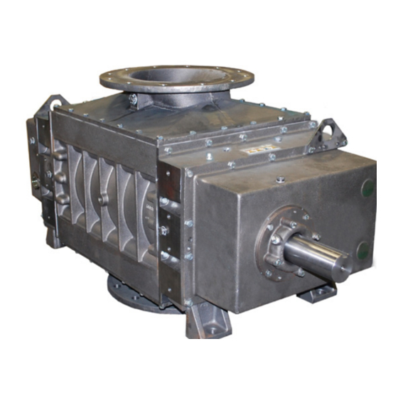
PD Plus
OPERATOR'S MANUAL
Models
9016
9020
9027
Horizontal Air Flow
Vertical Air Flow
Horizontal Flow, Single Envelope
Gastight Vertical Flow, Single
Envelope Gastight Horizontal Flow,
Double Envelope Gastight Vertical
Flow, Double Envelope Gastight
All rights reserved. Product information and specifications subject to change.
Tuthill Springfield
Tuthill
Rotary Positive Displacement Blower
Copyright © 2020 Tuthill Springfield
|
tuthillvacuumblower.com
Manual 2008 Rev A p/n 2008
|
800.825.6937
Advertisement
Table of Contents

Related Manuals for Tuthill PD Plus 9000 Series


Summary of Contents for Tuthill PD Plus 9000 Series
- Page 1 Vertical Air Flow Horizontal Flow, Single Envelope Gastight Vertical Flow, Single Envelope Gastight Horizontal Flow, Double Envelope Gastight Vertical Flow, Double Envelope Gastight Copyright © 2020 Tuthill Springfield All rights reserved. Product information and specifications subject to change. Tuthill Springfield tuthillvacuumblower.com 800.825.6937...
- Page 2 No part of this publication may be reproduced or used in any form by any means - graphic, electronic or mechanical, including photocopying, recording, taping or information storage and retrieval systems - without the written permission of Tuthill Springfield. Copyright © 2020 Tuthill Springfield...
-
Page 3: Table Of Contents
Table of Contents Introduction .................. 1 Applicable Documentation ..............1 Scope of Manual ................... 1 Conventions and Data Plate ............2 Graphic Conventions in this Manual ............. 2 Data Plate ....................3 Lifting .................... 5 Description ................... 6 Flow by Direction................... 7 Specifications .................. - Page 4 Table of Contents Frequently Asked Questions Regarding Lubrication ....17 Hazards Associated With Breakdown or Ignition of Lubrication ................17 Lubrication – Integral Pressure (19, 86, 55, 82, 66, 69 Series) ... 17 Oil Filter ..................17 Oil Pressure Adjustment ............18 Oil Cooler .................
- Page 5 Table of Contents Spare Parts ..................29 Factory Service and Repair ..............29 Long-Term Storage ................30 Disassembly and Reassembly ..........31 Disassembly of Blower ............... 31 Free End Disassembly ............. 31 Gear End Disassembly (Series 17/19/46/55/57/81/82/86) ..31 Gear End Disassembly (Series 64/66/67/69) ......31 End Plate and Rotor Disassembly ..........
- Page 6 Table of Contents Assembly Clearances ..............39 Torque Chart ................40 Recommended Lubricants ............41 Recommended Lubricants for Rotary Blowers and Vacuum Boosters ....................41 Special Tool Drawings ............... 43 Parts List ..................... 44 Assembly Drawings ................50 Manual 2008 Rev A p/n 2008...
-
Page 7: Introduction
INTRODUCTION APPLICABLE DOCUMENTATION CONGRATULATIONS on the purchase of a new PD PLUS Rotary Positive Displacement Blower from Tuthill Springfield. Please examine the blower The applicable documents associated with this for shipping damage, and if any damage is found, manual are: report it immediately to the carrier. -
Page 8: Conventions And Data Plate
CONVENTIONS AND DATA PLATE GRAPHIC CONVENTIONS IN THIS OTE: Indicates a procedure, practice, or condition that should be followed in MANUAL order for the equipment to function in the manner intended. This manual is the result of a risk assessment CAUTION according to the applicable documents referenced in Applicable Documentation on page 1. -
Page 9: Data Plate
Conventions and Data Plate DATA PLATE MAWP YEAR Tuthill Vacuum & Blower Systems MAX RPM 4840 West Kearney Street Springfield, Missouri USA 65803 READ INSTRUCTION MANUAL BEFORE OPERATION OR BODILY HARM MAY RESULT WARNING WARNING CAUTION CAUTION Do not operate without... - Page 10 Conventions and Data Plate MODEL NUMBER: The specific model of the blower SERIAL NUMBER: Unique to each blower YEAR: Year of manufacture MAWP: Maximum Allowable Working Pressure The standard MAWP is per Table 4-2 – Maximum Operating Limits on page 8.
-
Page 11: Lifting
LIFTING WARNING The blower must be handled using an appropriate device such as a fork truck or appropriate lifting device. See Table 4-1 on page 8 for approximate weights. Care should be taken to assure blower does not over-turn during handling and installation. Manual 2008 Rev A p/n 2008... -
Page 12: Description
Tuthill Springfield model 9000 Series rotary lobe Likewise, if the possibility exists that flow to the blowers are positive displacement type blowers, blower inlet may be cut off during normal operation... -
Page 13: Flow By Direction
Description INLET INLET INLET DISCHARGE DISCHARGE DISCHARGE Figure 4-1 – General Operation Principle FLOW BY DIRECTION WARNING Refer to diagrams in this manual for proper rotation and orientation in inlet and discharge. VERTICAL FLOW HORIZONTAL FLOW INTAKE DISCHARGE INTAKE DISCHARGE DISCHARGE INTAKE DISCHARGE... -
Page 14: Specifications
Description SPECIFICATIONS APPROXIMATE OIL CAPACITY APPROXIMATE WEIGHT MODEL PORT SIZE VERTICAL HORIZONTAL VERTICAL HORIZONTAL FLOW FLOW FLOW FLOW 2000 lb 2000 lb 9016 8.0 gal (30.3 L)* 5.0 gal (18.9 L)* 12 in. (305 mm) 2400 (907 kg) (907 kg) 2300 lb 2300 lb 9020... - Page 15 Assembly Clearances on page 39, will not have the operating limits specified here. Contact your Tuthill Springfield sales representative for specific information. Special attention must be paid when a blower has a higher than standard ambient suction temperature.
-
Page 16: General
Tuthill Factory prior to the purchase of the product, designed specifically for the gas application. - Page 17 Installation base. Shims may be needed for alignment. Loosen WARNING the foot hold-down screws to check foot contact with the mounting surface. Mount the base on a Upon completion of the installation, and solid foundation or heavy flooring, using shims before applying power, rotate the drive as necessary at bolting points to prevent warping shaft by hand.
-
Page 18: Location
Blower Air Intake information. To minimize maintenance, supply the blower with Blowers from Tuthill Springfield are internally the cleanest air possible. The air must not contain and externally treated after factory assembly any flammable or toxic gases, as the blower will and testing to protect against rusting in normal concentrate these gases. -
Page 19: Soft Foot
SAFETY Soft Foot Soft foot is a condition in which one of the blower Tuthill Springfield recommends the use of relief feet does not sit flat on the base. Soft foot is valves to protect against excessive pressure or usually due to irregularities in the surface to which vacuum conditions. -
Page 20: Lubrication
Installation LUBRICATION DANGER Every blower from Tuthill Springfield is factory- Assure that properly sized vacuum breaks/ tested, oil-drained, and shipped dry to its relief valves are used on the inlet side of installation point. Fill both oil reservoirs to the the blower. -
Page 21: Filling Procedure
Installation Filling Procedure 2. Slowly pour oil through the fill until oil appears in the oil sight glass. Bring the oil level to the center of the sight glass. See Recommended Lubricants on page 41 for suggested lubricants and grease. 3. -
Page 22: Recommended Oil Change Intervals
Installation Recommended Oil Change Intervals Table 5-1 should only be used as an approximate guide. For best results, an oil sampling program is recommended. The initial oil change should occur after the first 200 hours of operation. Thereafter, frequency of oil changes will depend on the operating conditions. -
Page 23: Frequently Asked Questions Regarding Lubrication
Acid Number (TAN) and a change of 10 percent in Change the oil filter element with every oil change. the base viscosity. Filters are available from Tuthill Springfield, or from any authorized distributor or service center. Several things are happening as the lubricant goes through the blower. -
Page 24: Oil Pressure Adjustment
Installation PIPING CONNECTIONS Oil Pressure Adjustment The oil pressure on each unit has been preset at WARNING the factory during the load testing. Generally the oil pressure should not require adjustment once the Pipe loading on the blower should be unit is installed and in operation. -
Page 25: Hazards Associated With Hazardous Process Fluids
Installation MOTOR DRIVES Hazards Associated With Hazardous Process Fluids Two drive connections commonly used are direct drive and V-belt drive. DANGER It shall be the responsibility Direct Coupled of the installer to ensure that piping is adequate, sealing When installing the motor directly to the blower, between pipe joints is adequate align the shafts to the coupling according to the for the process fluids and... -
Page 26: Setting V-Belt Tension
Installation Adjust the belt tension to the manufacturer’s specifications using a belt tension tester. Check new belts for proper tension after 24 hours of run time. When manufacturer data is not available, Too Tight industry guidelines recommend 1/64 in. deflection for each inch of span (0.157 mm deflection per Too Tight centimeter of span) at 8 –... - Page 27 Installation V-Belt Troubleshooting PROBLEM POSSIBLE CAUSES SOLUTION Belts slip (sidewalls glazed) Not enough tension Replace belts; apply proper tension. Shock load Apply proper tension. Drive squeals Not enough arc of contact Increase center distance. Heavy starting load Increase belt tension. Replace set of belts and install Broken cord caused by prying on sheave correctly.
-
Page 28: Motor And Electrical Connections
Installation Motor and Electrical Connections WARNING The motor and connections shall be protected to assure that product and environmental condensation does not come in contact with the electrical connections. It is the responsibility of the installer to assure that the motor is in compliance with the latest edition of IEC 60204-1 and all electrical connections are performed per IEC 60204-1, this includes overcurrent protection. -
Page 29: Operation
The booster is not intended to be used in blower. with explosive products or in explosive environments unless fully approved by Tuthill 2. Be certain that inlet piping is free of debris. If Factory prior to the purchase of the product, an open outdoor air intake is used, be sure the designed specifically for the gas application. -
Page 30: Start-Up Checklist
Operation Carry out initial operation under “no load” if the blower is part of a process system where conditions by opening all valves and venting the conditions may vary. At the first opportunity, stop discharge to the atmosphere, if possible. Then, the blower and clean or remove the inlet filter. -
Page 31: Operating
DANGER for detailed information assistance. The booster is not intended to be used with explosive products or in explosive environments unless fully approved by Tuthill CAUTION Factory prior to the purchase of the product, designed specifically for the gas application. -
Page 32: Operation
Tuthill Springfield cannot be 4. Turn the water on and adjust the flow as responsible for damage which may result recommended for the individual blower. Make should this build-up occur. - Page 33 Operation Care must be taken not to overload or overheat the blower during this procedure. 1. Isolate the blower from the moist system piping, allowing the blower to intake atmospheric air. Operate the blower under a slight load, allowing the blower to heat within safe limits.
-
Page 34: Maintenance
MAINTENANCE GENERAL CAUTION Regular inspection of the blower and its During routine maintenance, inspect and installation, along with complete checks on assure that guards are in place and secure. operating conditions, will pay dividends in added life and usefulness. Also, service the drive per Pay special attention to lubrication of timing gears the manufacturer’s instructions and lubricate and bearings according to the information in... -
Page 35: Spare Parts
For major repairs not covered in this manual, Data Sheet to be completed and forwarded to contact the nearest Tuthill Springfield service Tuthill Corporation on any unit being returned representative. for any reason which has been handling or When ordering parts, supply the blower nameplate involved with hazardous gases or materials. -
Page 36: Long-Term Storage
Maintenance 10. If possible, rotate the drive shaft by hand at least monthly to prevent seals from setting in one position. When returning a blower to the factory for repair under warranty, please note the factory will not accept any unit that arrives without authorization. -
Page 37: Disassembly And Reassembly
DISASSEMBLY AND REASSEMBLY DISASSEMBLY OF BLOWER Gear End Disassembly (Series 64/66/67/69) 1. Drain lubrication, and disconnect or remove the 7. Remove cap screws and water cooling hosing. external oil lines, filter, and cooler if applicable. Discard O-ring. Remove cap screws. Use two Port fitting may also be removed. -
Page 38: End Plate And Rotor Disassembly
Disassembly and Reassembly ASSEMBLY OF BLOWER marks. Using the same puller, remove the gear hub and solid gear. The assembly procedure is generally the same for 13. Remove cap screws and retainer rings. all series, but notations are made where there are differences. -
Page 39: Lip Seal Installation (Series 55/57/64/66/67/69/81/82)
Disassembly and Reassembly Lip Seal Installation 9. Grease four O-rings and install in the gear end plate. Run a continuous bead of sealer, about (Series 55/57/64/66/67/69/81/82) 1/8 in. (3 mm) wide around the perimeter of the housing, encircling each bolt hole and dowel 4. -
Page 40: Free End Assembly
Disassembly and Reassembly 15. Heat the solid gear and the hub of the two- piece gear to 350°F (177°C). Install the solid gear and hub onto the rotor shafts. Secure with As the second gear is installed, the helical washers and cap screws. Do not install the teeth will cause the rotor to turn. -
Page 41: Adjusting Interlobe Clearance
Disassembly and Reassembly Adjusting Interlobe Clearance Complete Drive End Assembly 23. The outer gear shell is fastened to the 26. Clean and remove all burrs from the mating inner hub with four cap screws and located surfaces of the gear and drive shaft. Install cap with two dowel pins. -
Page 42: Complete Free End Assembly (Series 19/55/66/69/82/86)
Disassembly and Reassembly Complete Free End Assembly (Series 19/55/66/69/82/86) 32. Install oil pump drive shaft, oil slinger, and secure with cap screws. Put sealer on the end cover. Grease and install O-ring. Align oil pump coupling with slot in drive shaft and install plate. -
Page 43: Troubleshooting
TROUBLESHOOTING Although Tuthill Springfield blowers are well designed and manufactured, problems may occur due to normal wear and the need for readjustment. The following chart lists symptoms that may occur along with probable causes and remedies. SYMPTOM PROBABLE CAUSE REMEDIES Gear housing not Tighten gear housing bolts. - Page 44 Troubleshooting SYMPTOM PROBABLE CAUSE REMEDIES Too much or too little Check oil level. See Lubrication on page 14. oil in gear reservoir Too low operating Increase blower speed within limits. speed Clogged filter or Remove cause of obstruction. Excessive silencer blower Excessive pressure temperature...
-
Page 45: Assembly Clearances
ASSEMBLY CLEARANCES MODEL GEAR END FREE END INTERLOBE TIP-DOWEL TIP-PORT 0.007 – 0.010 in. 0.012 – 0.017 in. 0.013 – 0.018 in. 0.009 – 0.013 in. 0.013 – 0.018 in. 9016 (0.18 – 0.25 mm) (0.30 – 0.43 mm) (0.33 – 0.46 mm) (0.23 –... -
Page 46: Torque Chart
TORQUE CHART Data shown represents “wet” torque values. PART DESCRIPTION TORQUE 3 ft-lb CAP SCREW 10-32UNF (4 N-m) 6 ft-lb CAP SCREW 1/4"-20UNC GR5 (8 N-m) 13 ft-lb CAP SCREW 5/16"-18UNC GR5 (17 N-m) 23 ft-lb CAP SCREW 3/8"-16UNC GR5 (31 N-m) 57 ft-lb CAP SCREW 1/2"-13UNC GR5... -
Page 47: Recommended Lubricants
RECOMMENDED LUBRICANTS RECOMMENDED LUBRICANTS FOR Tuthill offers oils that are suitable for a wide range of operating temperatures that are based on TUTHILL BLOWER AND VACUUM model, operating speed and discharge temperature of the product. BOOSTERS Tuthill positive displacement blowers and vacuum... - Page 48 Recommended Lubricants MD BLOWER & BOOSTER LUBRICANTS SPECIFICATIONS: PRODUCTS MD ONE MD PLUS MD MAX MD FG VISCOSITY INDEX @40°C, CST 99.1 231.7 340.9 99.3 @100°C, CST 14.4 27.6 37.2 13.9 FLASH POINT 510 (266) 480 (249) 491 (255) 515 (268) °F (°C) POUR POINT - 44 (-43)
-
Page 49: Special Tool Drawings
SPECIAL TOOL DRAWINGS 2.750 2.990 .378 69.85 .125 Ø 4.915 Ø 4.805 Ø 4.915 Ø 5.508 4.910 2.250 Ø 2.990 4.800 4.910 5.507 124.841 121.920 124.841 57.15 139.903 124.714 122.047 124.714 139.878 45° .039 × 45° (1 MM) 2.250 22.5 57.15 .886 2.500... -
Page 50: Parts List
Parts List PARTS LIST Parts List for Model 9000 17/46 Series Blowers ITEM ITEM PART DESCRIPTION PART DESCRIPTION O-Ring Mechanical Seal Rotor Pipe Plug Housing Pipe Plug End Plate Lifting Lug Drive End Cover Cap Screw Free End Cover Spacer Timing Gear Set O-Ring Bearing, Drive End... - Page 51 Parts List Parts List for Model 9000 19/86 Series Blowers ITEM ITEM PART DESCRIPTION PART DESCRIPTION Heat Exchanger Mechanical Seal Rotor Pipe Plug Housing Tube, Al End Plate Tube, Al Drive End Cover Lifting Lug Free End Cover Cap Screw Timing Gear Set O-Ring Bearing, Drive End...
- Page 52 Parts List Parts List for Model 9000 55/82 Series Blowers ITEM ITEM PART DESCRIPTION PART DESCRIPTION Reducer Bushing Mechanical Seal Rotor Heat Exchanger Housing Pipe Plug End Plate O-Ring Drive End Cover Tube, Al Free End Cover Tube, Al Timing Gear Set Lifting Lug Bearing, Drive End Cap Screw...
- Page 53 Parts List Parts List for Model 9000 57/81 Series Blowers ITEM ITEM PART DESCRIPTION PART DESCRIPTION Oil Sight Gauge Mechanical Seal Rotor O-Ring Housing Pipe Plug End Plate Pipe Plug Drive End Cover Pipe Plug Free End Cover O-Ring Timing Gear Set Lifting Lug Bearing, Drive End Cap Screw...
- Page 54 Parts List Parts List for Model 9000 64/67 Series Blowers ITEM ITEM PART DESCRIPTION PART DESCRIPTION Seal Adapter Mechanical Seal Rotor O-Ring Housing Cap Screw End Plate Pipe Plug Drive End Cover Pipe Plug Free End Cover O-Ring Timing Gear Set Pipe Plug Bearing, Drive End O-Ring...
- Page 55 Parts List Parts List for Model 9000 66/69 Series Blowers ITEM ITEM PART DESCRIPTION PART DESCRIPTION Heat Exchanger Mechanical Seal Rotor Pipe Plug Housing O-Ring End Plate Tube, Al Drive End Cover Tube, Al Free End Cover Lifting Lug Timing Gear Set Cap Screw Bearing, Drive End O-Ring...
-
Page 56: Assembly Drawings
Assembly Drawings ASSEMBLY DRAWINGS Model 9000 17/46 – Cutaway View Manual 2008 Rev A p/n 2008... - Page 57 Assembly Drawings Model 9000 19/86 – Cutaway View Manual 2008 Rev A p/n 2008...
- Page 58 Assembly Drawings Model 9000 19/86 – Cutaway View Manual 2008 Rev A p/n 2008...
- Page 59 Assembly Drawings Model 9000 55/82 – Cutaway View Manual 2008 Rev A p/n 2008...
- Page 60 Assembly Drawings Model 9000 55/82 – Cutaway View Manual 2008 Rev A p/n 2008...
- Page 61 Assembly Drawings Model 9000 57/81 – Cutaway View Manual 2008 Rev A p/n 2008...
- Page 62 Assembly Drawings Model 9000 64/67 – Cutaway View Manual 2008 Rev A p/n 2008...
- Page 63 Assembly Drawings Model 9000 66/69 – Cutaway View Manual 2008 Rev A p/n 2008...
- Page 64 Assembly Drawings Model 9000 66/69 – Cutaway View Manual 2008 Rev A p/n 2008...
- Page 66 WARRANTY – BLOWER PRODUCTS Subject to the terms and conditions hereinafter set forth and set forth in General Terms of Sale, Tuthill Springfield (the Seller) warrants products and parts of its manufacture, when shipped, and its work (including installation and start-up) when performed, will be of good quality and will be free from defects in material and workmanship.
- Page 67 NOTES: IMPORTANT All blowers manufactured by Tuthill Springfield are date coded at time of shipment. In order to assure you of the full benefits of the product warranty, please complete, tear out and return the product registration card, or register online at tuthillvacuumblower.com.
- Page 68 VACUUM & BLOWER SYSTEMS TUTHILL CORPORATION 4840 West Kearney Street Springfield, Missouri USA 65803-8702 O 417.865.8715 800.825.6937 F 417.865.2950 Manual 2008 Rev A p/n 2008 tuthillvacuumblower.com 01/20 Copyright © 2020 Tuthill Springfield All rights reserved. Product information and specifications subject to change.
Need help?
Do you have a question about the PD Plus 9000 Series and is the answer not in the manual?
Questions and answers