Table of Contents
Advertisement
WARNING: Do Not Operate Before Reading Manual
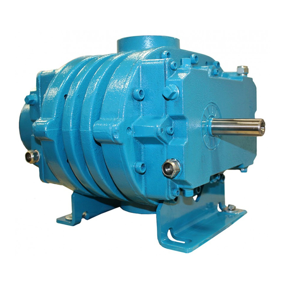
CP Series
OPERATOR'S MANUAL
Models
2002
3002
4002
2004
3003
4005
3006
4007
Grease Lubrication / Air Service
Splash Lubrication / Air Service
All rights reserved. roduct in ormation and speci cations sub ect to change.
Tuthill Vacuum & Blower Systems
5003
6005
5006
6008
5009
6015
Copyright © 2018 Tuthill Vacuum & Blower Systems
www.tuthillvacuumblower.com
M-D Pneumatics
™
Rotary Positive Displacement Blower
Manual 2017 Rev C p/n 2017
7006
7011
7018
800.825.6937
Advertisement
Table of Contents
Troubleshooting

Related Manuals for Tuthill 2002


Summary of Contents for Tuthill 2002
- Page 1 6015 7018 Grease Lubrication / Air Service Splash Lubrication / Air Service Copyright © 2018 Tuthill Vacuum & Blower Systems All rights reserved. roduct in ormation and speci cations sub ect to change. Tuthill Vacuum & Blower Systems www.tuthillvacuumblower.com 800.825.6937...
- Page 2 No part of this publication may be reproduced or used in any form by any means – graphic, electronic or mechanical, including photocopying, recording, taping or information storage and retrieval systems – without the written permission of Tuthill Vacuum & Blower Systems. Copyright © 2018 Tuthill Vacuum & Blower Systems...
-
Page 3: Table Of Contents
Table of Contents Introduction .................. 1 Applicable Documentation ..............1 Scope of Manual ................... 1 Conventions and Data Plate ............2 Graphic Conventions in this Manual ............. 2 Data Plate ....................3 Lifting .................... 5 Description ................... 6 Flow by Direction and Rotation ............. 7 Specifi... - Page 4 Table of Contents Frequently Asked Questions Regarding Lubrication ....17 Hazards Associated With Breakdown or Ignition of Lubrication .............. 17 Release Lubricated Bearings – Grease Lubrication Series Only ..........17 Piping Connections ................18 Hazards Associated With Hazardous Process Fluids ....18 Blockage or Restriction ............
- Page 5 Table of Contents Disassembly and Reassembly ..........30 Disassembly of Blower ............... 30 Reassembly of Blower ................ 33 Adjusting Rotor Interlobe Clearance ........36 Lubrication, Final Assembly and Mounting ......37 Troubleshooting ................. 38 Assembly Clearances ..............40 Torque Chart ..................41 Recommended Lubricants ............
- Page 6 Table of Contents Manual 2017 Rev C p/n 2017...
-
Page 7: Introduction
INTRODUCTION APPLICABLE DOCUMENTATION CONGRATULATIONS on the purchase of a new CP Series Rotary Positive Displacement Blower from Tuthill Vacuum & Blower Systems. Please The applicable documents associated with this examine the blower for shipping damage, and if manual are: any damage is found, report it immediately to the carrier. -
Page 8: Conventions And Data Plate
CONVENTIONS AND DATA PLATE GRAPHIC CONVENTIONS IN THIS OTE: Indicates a procedure, practice, or condition that should be followed in MANUAL order for the equipment to function in the manner intended. This manual is the result of a risk assessment CAUTION according to the applicable documents referenced in Applicable Documentation on page 1. -
Page 9: Data Plate
Conventions and Data Plate DATA PLATE MAWP YEAR Tuthill Vacuum & Blower Systems MAX RPM 4840 West Kearney Street Springfield, Missouri USA 65803 READ INSTRUCTION MANUAL BEFORE OPERATION OR BODILY HARM MAY RESULT WARNING WARNING CAUTION CAUTION Do not operate without... - Page 10 Conventions and Data Plate MODEL NUMBER: The speci c model of the blower SERIAL NUMBER: Unique to each blower YEAR: Year of manufacture MAWP: Maximum Allowable Working Pressure The standard MAWP is per Table 4-2 – Maximum Operating Limits on page 9.
-
Page 11: Lifting
LIFTING WARNING The blower must be handled using an appropriate device such as a fork truck or appropriate lifting device. See Table 4-1 on page 8 for approximate weights. Care should be taken to assure blower does not over-turn during handling and installation. Manual 2017 Rev C p/n 2017... -
Page 12: Description
Likewise, if the possibility exists that ow to the Tuthill Vacuum & Blower Systems CP Series model blower inlet may be cut off during normal operation rotary lobe blowers are positive displacement type... -
Page 13: Flow By Direction And Rotation
Description INLET INLET INLET DISCHARGE DISCHARGE DISCHARGE Figure 4-1 – General Operation Principle FLOW BY DIRECTION AND ROTATION WARNING Refer to diagrams in this manual for proper rotation and orientation in inlet and discharge. VERTICAL FLOW HORIZONTAL FLOW INTAKE DISCHARGE INTAKE DISCHARGE DISCHARGE... -
Page 14: Specifi Cations
VERTICAL FLOW HORIZONTAL FLOW MODEL PORT SIZE WEIGHT GEAR DRIVE GEAR DRIVE 3.4 oz 1.7 oz 1 in. 2002 – – 5,275 41 lb (19 kg) (101 mL) (50 mL) (25 mm) 3.4 oz 1.7 oz 2 in. 2004 –... - Page 15 Description MAXIMUM MAXIMUM MAXIMUM MODEL PRESSURE MAXIMUM VACUUM* TEMPERATURE MAWP DIFFERENTIAL* RISE* 2002 5,275 12 psi (827 mbar) 16 inch-Hg (542 mbar) 225°F (125°C) 15 psi (1,034 bar) 2004 5,275 7 psi (483 mbar) 16 inch-Hg (542 mbar) 185°F (103°C)
- Page 16 Assembly Clearances on page 40, will not have the operating limits speci ed here. Contact your WARNING Tuthill Vacuum & Blower Systems sales representative for speci c information. The maximum allowable working pressure (MAWP) is based on the absolute pressure of the blower housing and is NOT the maximum allowable pressure differential.
-
Page 17: Installation
INSTALLATION GENERAL WARNING Customers are warned to provide adequate DANGER protection, warning and safety equipment necessary to protect personnel against The blower is not intended to be used hazards in the installation and operation of with explosive products or in explosive this equipment in the system or facility. -
Page 18: Manual 2017 Rev C P/N
Installation base. Shims may be needed for alignment. Loosen WARNING the foot hold-down screws to check foot contact with the mounting surface. Mount the base on a Upon completion of the installation, and solid foundation or heavy ooring, using shims as before applying power, rotate the drive necessary at bolting points to prevent warping the shaft by hand. -
Page 19: Location
See Motor Drives on page 19 for more information. To minimize maintenance, supply the blower with Blowers from Tuthill Vacuum & Blower Systems the cleanest air possible. The air must not contain are internally and externally treated after factory... -
Page 20: Soft Foot
SAFETY Soft Foot Soft foot is a condition in which one of the blower Tuthill Vacuum & Blower Systems recommends feet does not sit at on the base. Soft foot is the use of relief valves to protect against excessive usually due to irregularities in the surface to which pressure or vacuum conditions. -
Page 21: Lubrication
Installation LUBRICATION DANGER Every blower from Tuthill Vacuum & Blower Assure that properly sized vacuum breaks/ Systems is factory-tested, oil-drained, and shipped relief valves are used on the inlet side of dry to its installation point. Fill both independent oil the blower. -
Page 22: Filling Procedure
Installation Filling Procedure Most CP Series blowers are shipped from See Figure 5-3. See Recommended Lubricants the factory in a left hand drive, vertical ow on page 42 for suggested lubricants and con guration. If drive shaft location is changed, grease. -
Page 23: Frequently Asked Questions Regarding Lubrication
The lubricant will resistance and good mechanical stability, such as discolor because of overheating. An indicator of the PneuLube grease, available from a local Tuthill breakdown of a lubricant is the increase in the Total Vacuum & Blower System professional. Use... -
Page 24: Piping Connections
Installation Hazards Associated With Hazardous Process Fluids To avoid blowing out the drive shaft seal, do not grease too rapidly. DANGER OTE: See Figure 5-3 for locations of grease It shall be the responsibility ttings and grease reliefs for horizontal of the installer to ensure that and vertical ow blowers. -
Page 25: Motor Drives
Installation MOTOR DRIVES Adjust the belt tension to the manufacturer’s speci cations using a belt tension tester. Check new belts for proper tension after 24 hours of run Two drive connections commonly used are direct time. When manufacturer data is not available, drive and V-belt drive. -
Page 26: Setting V-Belt Tension
Installation Setting V-Belt Tension As such, it is recommended to check belt tension monthly and make any manual adjustments found necessary. Proper belt tension is essential to long blower life. Figure 5-4, Figure 5-5, and the following 1. Turn off and lock out power. procedure are provided to aid in eld-adjusting V-belts (when the blower is so equipped) for 2. -
Page 27: V-Belt Troubleshooting
Installation V-Belt Troubleshooting PROBLEM POSSIBLE CAUSES SOLUTION Belts slip (sidewalls Not enough tension Replace belts; apply proper tension. glazed) Shock load Apply proper tension. Drive squeals Not enough arc of contact Increase center distance. Heavy starting load Increase belt tension. Replace set of belts and install Broken cord caused by prying on sheave correctly. -
Page 28: Motor And Electrical Connections
Installation MOTOR AND ELECTRICAL CONNECTIONS WARNING The motor and connections shall be protected to assure that product and environmental condensation does not come in contact with the electrical connections. It is the responsibility of the installer to assure that the motor is in compliance with the latest edition of IEC 60204-1 and all electrical connections are performed per IEC 60204-1, this includes overcurrent protection. -
Page 29: Operation
OPERATION GENERAL WARNING The blower can generate excessive noise. Hearing DANGER protection is required while the The blower is not intended to be used unit is in operation. with explosive products or in explosive environments. The blower is not intended Before starting the blower for the rst time under to be used in applications that include power, recheck the installation thoroughly to... -
Page 30: Start-Up Checklist
Operation 7. Check motor rotation by momentarily pushing Assuming all tests are satisfactory, the blower will the START button and then checking the ow now be ready for continuous full-load operation. direction of the blower. Reverse the motor During the rst several days, check periodically to connections if the ow is in the wrong direction. -
Page 31: Stopping
Operation “Bump” the unit with the motor to check rotation (counterclockwise when facing the shaft) and to be certain it turns freely and smoothly. Start the unit and operate it for 30 minutes at no load. During this time, feel the cylinder for hot spots. -
Page 32: Recommended Shutdown Procedure To Minimize Risk Of Freezing Or Corrosion
Operation RECOMMENDED SHUTDOWN 4. If the blower is being taken out of commission for an extended period of time, see Long- PROCEDURE TO MINIMIZE RISK OF Term Storage on page 29. FREEZING OR CORROSION When an air piping system has high humidity or moisture, water condensation can occur after the blower is shut down and it begins to cool. -
Page 33: Maintenance
MAINTENANCE GENERAL CAUTION Regular inspection of the blower and its During routine maintenance, inspect and installation, along with complete checks on assure that guards are in place and secure. operating conditions, will pay dividends in added life and usefulness. Also, service the drive per Pay special attention to lubrication of timing gears the manufacturer’s instructions and lubricate and bearings according to the information in... -
Page 34: Spare Parts
FACTORY SERVICE AND REPAIR presence of water or solids. Slight discoloration of the oil should not necessitate an oil change. With proper care, Tuthill Vacuum & Blower Systems blowers will give years of reliable service. SPARE PARTS The parts are machined to close tolerances... -
Page 35: Long-Term Storage
Maintenance 10. If possible, rotate the drive shaft by hand at least monthly to prevent seals from setting in one position. When returning a blower to the factory for repair, under warranty, please note the factory will not accept any unit that arrives without authorization. -
Page 36: Disassembly And Reassembly
DISASSEMBLY AND REASSEMBLY DISASSEMBLY OF BLOWER Gears are not exposed for visual inspection prior to disassembly. Inspect the gears for the following: WARNING • Broken teeth • Chipped teeth Before performing any repair or replacement, • Uneven wear disconnect and lock out power. •... - Page 37 Disassembly and Reassembly DRIVE DRIVEN GEAR GEAR Figure 8-2 – Timing Marks Advanced 3 Teeth (Reference Figure 8-4 – Pulling Driven Gear with Bar Puller Marks Aligned) OTE: If the unit becomes locked up, switch 5. Align the reference marks (see Figure 8-2). gears.
- Page 38 Disassembly and Reassembly 12. Remove the 10 cap screws that secure the 14. Press the rotors out of the free (non-drive) drive end plate to the housing. end plate in press if available. If press is not available, support the end plate and rotors in 13.
-
Page 39: Reassembly Of Blower
Disassembly and Reassembly Figure 8-10 – Rotors Assembled on Drive End Plate (Model 4000 with Tri-Lobe Rotors Shown) Figure 8-9 – Tapping Bearings Out of End Plates 16. Remove the seals from both end plates with a punch or dull chisel. The seals will be damaged during removal and must be replaced. - Page 40 Disassembly and Reassembly 2-LOBE UNITS ALL MODELS DRIVE DRIVEN 3-LOBE UNITS 4000 MODELS DRIVEN Figure 8-12 – Checking Gear End Clearances DRIVE 3000 AND 5000 MODELS DRIVEN DRIVE Figure 8-14 – Rotor Keyway Positions Figure 8-13 – Check Drive End Clearances 1.
- Page 41 Disassembly and Reassembly 5. If clearances check OK, put a spacer on each 13. Apply a bead of a good quality RTV silicone shaft. Timing shims that were removed should sealant to the inner surface of the drive end be put back on the shaft from which they were cover that mates to the drive end plate.
-
Page 42: Adjusting Rotor Interlobe Clearance
Disassembly and Reassembly Adjusting Rotor Interlobe Clearance 1. Use feeler gauges to take interlobe readings, and record them on each side of housing as indicated in Figure 8-15. As shim is removed or added behind the helical gear, the gear rotates as it is moved in or out and the driven rotor turns with it, thus changing the clearance between rotor lobes. -
Page 43: Lubrication, Final Assembly And Mounting
Disassembly and Reassembly Lubrication, Final Assembly and SHIM MODEL CHANGE Mounting CHANGE 2000 1. Apply a bead of a high-quality RTV silicone 3000/4000/5000 sealant to the inner surface of the gear end 6000 cover that mates to the gear end plate. Install the gear end cover with cap screws and tighten 7000 evenly. -
Page 44: Troubleshooting
TROUBLESHOOTING Although Tuthill Vacuum & Blower Systems blowers are well designed and manufactured, problems may occur due to normal wear and the need for readjustment. The following chart lists symptoms that may occur along with probable causes and remedies. SYMPTOM... - Page 45 Troubleshooting SYMPTOM PROBABLE CAUSE REMEDIES Too much or too little Check oil level. See Lubrication on page 15. oil in gear reservoir Too low operating Increase blower speed within limits. speed Clogged lter or Remove cause of obstruction. Excessive silencer blower Excessive pressure temperature...
-
Page 46: Assembly Clearances
0.003 – 0.005 in. 0.008 – 0.011 in. 0.005 – 0.009 in. 0.002 – 0.004 in. 0.003 – 0.006 in. 2002 (0.10 – 0.18 mm) (0.08 – 0.13 mm) (0.20 – 0.28 mm) (0.13 – 0.23 mm) (0.05 – 0.10 mm) (0.08 –... -
Page 47: Torque Chart
TORQUE CHART Data shown represents “wet” torque values in foot-pounds and (Newton-meters). PART DESCRIPTION TORQUE 3 ft-lb CAP SCREW 10-32UNF (4 N-m) 6 ft-lb CAP SCREW 1/4"-20UNC GR5 (8 N-m) 13 ft-lb CAP SCREW 5/16"-18UNC GR5 (17 N-m) 23 ft-lb CAP SCREW 3/8"-16UNC GR5 (31 N-m) 57 ft-lb... -
Page 48: Recommended Lubricants
RECOMMENDED LUBRICANTS RECOMMENDED LUBRICANTS FOR ROTARY BLOWERS AND VACUUM BOOSTERS RECOMMENDED SYNTHETIC BASED LUBRICANTS FOR BLOWERS AMBIENT TUTHILL VISCOSITY GRADE ISO 100 ISO 150 TEMPERATURE Specific Gravity 0.859 0.865 0° to 32°F 16°C (62°F) (-18° to 0°C) Viscosity 91.8 cSt 142.7 cSt... - Page 49 Blowers used in oxygen-enriched service should use only non-flammable, PFPEsynthetic lubricant. Blowers used in hydrogen service should use only PneuLube synthetic oil. Tuthill Vacuum & Blower Systems cannot accept responsibility for damage to seals, O-rings and gaskets caused by use of synthetic lubricants not recommended by Tuthill Vacuum and Blower Systems...
-
Page 50: Special Tool Drawings
SPECIAL TOOL DRAWINGS 1.524 3.048 19.05 R .06 R .12 1.524 3.048 MODEL ±.001 ±.005 ±.005 ±.005 ±.005 ±.005 ±.005 MODEL ±.001 ±.005 ±.005 ±.005 ±.005 ±.005 ± 0.0254 ± 0.127 ± 0.127 ± 0.127 ± 0.127 ± 0.127 ± 0.127 ±... - Page 51 Special Tool Drawings This Page Intentionally Left Blank Manual 2017 Rev C p/n 2017...
-
Page 52: Parts List
Parts List Cutaway Drawing for Grease Lubrication / Air Service Manual 2017 Rev C p/n 2017... -
Page 53: Parts List For Model Cp Series - Grease Lubrication / Air Service
Parts List PARTS LIST Parts List for Model CP Series – Grease Lubrication / Air Service ITEM ITEM PART DESCRIPTION PART DESCRIPTION Lifting Lug Housing Mounting Foot * Not shown Drive End Plate Gear End Plate NOTES: Gear Cover Drive Rotor •... -
Page 54: Cutaway Drawing For Splash Lubrication / Air Service
Parts List Cutaway Drawing for Splash Lubrication / Air Service Manual 2017 Rev C p/n 2017... -
Page 55: Parts List For Model Cp Series - Splash Lubrication / Air Service
Parts List Parts List for Model CP Series – Splash Lubrication / Air Service ITEM ITEM PART DESCRIPTION PART DESCRIPTION Slinger Oil-2, Machine-1 Housing Roll Pin Mounting Foot Drive End Plate * Not shown Gear End Plate Gear End Cover NOTES: Drive Rotor Driven Rotor... - Page 56 Parts List This Page Intentionally Left Blank Manual 2017 Rev C p/n 2017...
-
Page 58: Warranty - Blower Products
WARRANTY – BLOWER PRODUCTS Subject to the terms and conditions hereinafter set forth and set forth in General Terms of Sale, Tuthill Vacuum & Blower Systems (the Seller) warrants products and parts of its manufacture, when shipped, and its work (including installation and start-up) when performed, will be of good quality and will be free from defects in material and workmanship. -
Page 59: Operating Data Form / Product Registration
NOTES: IMPORTANT All blowers manufactured by Tuthill Vacuum & Blower Systems are date-coded at time of shipment. In order to assure you of the full benefits of the product warranty, please complete, tear out and return the product registration card, or register online at tuthillvacuumblower.com. - Page 60 4840 West Kearney Street Spring eld, Missouri USA 65803-8702 O 417.865.8715 800.825.6937 F 417.865.2950 Manual 2017 Rev C p/n 2017 www.tuthillvacuumblower.com 4/18 Copyright © 2018 Tuthill Vacuum & Blower Systems All rights reserved. Product information and speci cations subject to change.
Need help?
Do you have a question about the 2002 and is the answer not in the manual?
Questions and answers