Table of Contents
Advertisement
WARNING: Do Not Operate Before Reading Manual
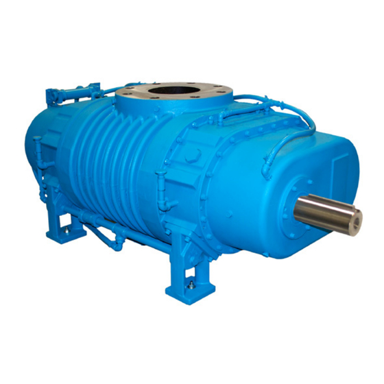
PD Plus
®
OPERATOR'S MANUAL
Models
1215
1236
1224
1248
1230
19/86 Series - Lip-Labyrinth (Air Service)
55/82 Series - Single Envelope Gastight
66/69 Series - Double Envelope Gastight
Tuthill Vacuum & Blower Systems
M-D Pneumatics
Rotary Positive Displacement Blower
tuthillvacuumblower.com
™
Manual 2009 1011 ENG
800.825.6937
Advertisement
Table of Contents
Troubleshooting

Related Manuals for Tuthill PD Plus 1215


Summary of Contents for Tuthill PD Plus 1215
- Page 1 WARNING: Do Not Operate Before Reading Manual PD Plus ® OPERATOR’S MANUAL Models 1215 1236 1224 1248 1230 19/86 Series - Lip-Labyrinth (Air Service) 55/82 Series - Single Envelope Gastight 66/69 Series - Double Envelope Gastight Tuthill Vacuum & Blower Systems tuthillvacuumblower.com 800.825.6937...
-
Page 2: Table Of Contents
TABLE OF CONTENTS SECTION PAGE 1. INTRODUCTION 1.1 APPLICABLE DOCUMENTATION 1.2 SCOPE OF MANUAL 2. CONVENTIONS AND DATA PLATE 2.1 GRAPHIC CONVENTIONS IN THIS MANUAL 2.2 DATA PLATE 3. LIFTING 4. DESCRIPTION 4.1 FLOW BY DIRECTION 4.2 SPECIFICATIONS 5. INSTALLATION 5.1 GENERAL 5.1.1 LOCATION 5.1.2 FOUNDATION... -
Page 3: Introduction
® Tuthill Vacuum & Blower Systems. Please examine the blower for shipping damage, and if any damage is found, report it immediately to the carrier. If the blower is to be installed at a later date make sure it is stored in a clean, dry location and rotated regularly. -
Page 4: Data Plate
2.2 DATA PLATE MAWP YEAR Tuthill Vacuum & Blower Systems MAX RPM 4840 West Kearney Street Springfield, Missouri USA 65803 READ INSTRUCTION MANUAL BEFORE OPERATION OR BODILY HARM MAY RESULT... -
Page 5: Lifting
Refer to diagrams in this manual for proper rotation and orientation in inlet and discharge. Tuthill Vacuum & Blower Systems model 1200 rotary lobe blowers are positive displacement type units, whose pumping capacity is determined by size, operating speed, and differential pressure conditions. -
Page 6: Flow By Direction
Consult your Tuthill Vacuum & Blower Systems sales professional if questions arise. 4.1 FLOW BY DIRECTION... -
Page 7: Specifications
Specially ordered blowers with nonstandard construction, or with rotor end clearances greater than shown within the Assembly Clearances table, will not have the operating limits specified here. Contact your Tuthill Vacuum & Blower Systems sales representative for specific information. NOTE Special attention must be paid when a blower has a higher than standard ambient suction temperature. -
Page 8: Installation
5. INSTALLATION 5.1 GENERAL DANGER The blower is not intended to be used with explosive products or in explosive environments. The blower is not intended to be used in applications that include hazardous and toxic gases. Consult the factory for support. DANGER It is the responsibility of the installer to assue that proper guarding is in place and compliant with all applicable regulatory requirements. - Page 9 NOTE In the event that your unit sustains damage while being shipped to your facility, do not return it to the factory without first obtaining shipping instructions from us. Protective covers and plugs should not be removed until the connection is being made. Mount the blower on a flat, level surface.
-
Page 10: Location
(See the Motor Drives section for more information.) Blowers from Tuthill Vacuum & Blower Systems are internally and externally treated after factory assembly and testing to protect against rusting in normal atmospheric conditions prior to installation. The maximum period of internal protection is considered to be up to 6 months under average conditions, provided closing plugs and seals are not removed. -
Page 11: Soft Foot
Figure 4 - Illustrations of Soft Foot 5.2 SAFETY Tuthill Vacuum & Blower Systems recommends the use of relief valves to protect against excessive pressure or vacuum conditions. These valves should be tested at initial start-up to be sure they are properly adjusted to relieve at or below the maximum pressure differential rating of the blower. -
Page 12: Lubrication
5.3 LUBRICATION Every blower from Tuthill Vacuum & Blower Systems is factory tested; oil drained and shipped dry to its installation point. Both oil reservoirs must be filled to the proper level before operation. The blower incorporates pressure lubrication with an integral oil pump, pressure relief valve, filter and oil-to- coolant heat exchanger. - Page 13 19/55 SERIES 66 SERIES HORIZONTAL FLOW HORIZONTAL FLOW ALTERNATE PRESSURE OIL FILL PLUG BREATHER PRESSURE OIL FILL PLUG DRIVE SHAFT GAUGE (1) EA END PLATE (1) EA END COVER GAUGE (1) EA END PLATE LOCATION ALTERNATE DRIVE COOLING WATER SHAFT LOCATION INLET 1”...
-
Page 14: Frequently Asked Questions Regarding Lubrication
5.3.2 FREQUENTLY ASKED QUESTIONS REGARDING LUBRICATION What is the functional detriment if the “wrong oil” is used? The lubricant is selected based on bearing and gear speed, and operating temperature. Too light of a lubricant increases wear by not separating the sliding surfaces and it will not remove the heat adequately. -
Page 15: Lubrication - Integral Pressure
5.4.3 OIL FILTER The oil filter is self-contained. With every oil change, change the oil filter element and it’s shell gasket, both available from Tuthill Vacuum and Blower Systems in Springfield, Missouri, or from any authorized distributor or service center. -
Page 16: Piping Connections
5.5 PIPING CONNECTIONS WARNING Pipe loading on the blower should be negligible as pipe loading can cause distortion of the blower. Use proper supports and pipe hangers to assure that there is no loading. NOTE Remove the protective covers from the inlet and outlet ports and inspect for dirt and foreign material. -
Page 17: Motor Drives
5.6 MOTOR DRIVES Two drive connections commonly used are direct drive and V-belt drive. 5.6.1 DIRECT COUPLED When installing the motor directly to the blower, align shafts to coupling in accordance with the coupling manufacturer’s instructions. Blowers shipped with motor directly coupled and mounted on a common base have been aligned prior to shipment and normally no further alignment is necessary. - Page 18 SETTING V-BELT TENSION Proper belt tension is essential to long blower life. The following diagrams and procedures are provided to aid in field adjusting V-belts (when Too Tight blower is so equipped) for maximum performance. Too Tight A visual inspection of the V-belt drive should yield the appearance shown in Figure 7.
-
Page 19: V-Belt Troubleshooting
5.6.3 V-BELT TROUBLESHOOTING PROBLEM POSSIBLE CAUSES SOLUTION Belts slip (sidewalls glazed) Not enough tension Replace belts; apply proper tension Shock load Apply proper tension Drive squeals Not enough arc of contact Increase center distance Heavy starting load Increase belt tension Broken cord caused by prying on sheave Replace set of belts and install correctly Overloaded drive... -
Page 20: Operation
6. OPERATION 6.1 GENERAL DANGER The blower is not intended to be used with explosive products or in explosive environments. The blower is not intended to be used in applications that include hazardous and toxic gases. Consult the factory for support. WARNING Do not operate without guards in place. -
Page 21: Start-Up Checklist
6.2 START-UP CHECKLIST We recommend that these startup procedures be followed in sequence and checked off ( ) in the boxes provided in any of the following cases: • During initial installation • After maintenance work has been performed • After any shutdown period •... -
Page 22: Stopping
WARNING The blower can generate excessive noise, hearing protection is required while the unit is in operation. CAUTION Do not touch hot surfaces. The upper limit of the blower operation is º F ( º C). Do not touch the blower while it is in operation and assure blower is cool when not in operation. -
Page 23: Shutdown
However, due to the wide variations in mineral content, pH, and chemical content of water that can be injected, Tuthill Vacuum & Blower Systems cannot be responsible for damage which may result should this build-up occur. Units should be inspected regularly to determine any problems. -
Page 24: Maintenance
3. For extended shutdown, inject a small amount of a light lubricating oil such as 3-in-One or a spray ® lubricant such as WD-40 into the inlet of the blower just prior to shutdown. (3-in-One and WD-40 are ® registered trademarks of WD-40 Company.) The lubricant will provide an excellent protective coating on the internal surfaces. -
Page 25: Regular Maintenance
Personnel should have a good background of mechanical experience and be thoroughly familiar with the procedures outlined in this manual. Major repairs not covered in this book should be referred to the nearest Tuthill Vacuum & Blower Systems service representative. -
Page 26: Factory Service & Repair
7.4 FACTORY SERVICE & REPAIR With proper care, Tuthill Vacuum & Blower Systems blowers will give years of reliable service. The parts are machined to very close tolerances and require special tools by mechanics who are skilled at this work. -
Page 27: Disassembly And Reassembly
8. DISASSEMBLY AND REASSEMBLY 8.1 DISASSEMBLY OF BLOWER 1. Drain lubrication from either end and disconnect all external oil lines. Do not attempt to remove oil distribution line bushing in the non-drive end plate until the end cover has been removed and the internal fittings are disconnected. -
Page 28: Assembly
Tuthill Vacuum & Blower Systems, to insure the rotor location is correct with the proper end clearance relative to the gear end plate. -
Page 29: Gear End Assembly
NOTE NOTE: Two wave springs are necessary for the proper pressure on the seal, but because of the pressure a tool as shown on page 23 is needed to press the retainer ring into its groove. The tool will center the labyrinth seal as it presses the retainer ring in place. -
Page 30: Free End Assembly
12. Install keys (24) into rotor shafts. Tight fit required. Coat shafts and key with anti-seize. If new gears are being installed, disassembly gear shell from hub. 13. Heat the gear hubs to 350° F (177° C) At this temperature they should fit easily to the rotor shafts. NOTE After heating, handle gear hubs with insulated gloves only. -
Page 31: Adjusting Interlobe Clearance
8.2.4 ADJUSTING INTERLOBE CLEARANCE 21. The timing gears are made up of two 2 LOBE LONG FEELER GAUGE pieces. The outer gear shells are fastened to the inner hubs with six cap RECORD A-A READING HERE screws and located with two dowel pins. RECORD B-B READING HERE By adding shims between a gear shell... -
Page 32: Completing Gear End Assembly
8.2.5 COMPLETING GEAR END ASSEMBLY 23. Press drive shaft bearing (50) on drive shaft (45). Remove the three cap screws from drive gear and install in the drive gear. Clean and remove all burrs from mating surfaces of the gear and drive shaft flange. -
Page 33: Troubleshooting
9. TROUBLESHOOTING Although Tuthill Vacuum & Blower Systems blowers are well designed and manufactured, problems may occur due to normal wear and the need for readjustment. The chart below lists symptoms that may occur along with probable causes and remedies. -
Page 34: Assembly Clearances
10. ASSEMBLY CLEARANCES Values shown in inches and millimeters. GEAR END FREE END INTERLOBE TIP-PORT MODEL TIP-DOWEL .011 - .014 .020 - .027 .025 - .032 .012 - .019 .021 - .027 1215 .28 - .36 .51 - .69 .64 - .81 .30 - .48 .53 - .69 .011 - .014... -
Page 35: Recommended Lubricants
Blowers used in hydrogen service should use only PneuLube synthetic oil. Tuthill Vacuum & Blower Systems cannot accept responsibility for damage to seals, O-rings and gaskets caused by use of synthetic lubricants not recommended by Tuthill Vacuum and Blower Systems. -
Page 36: Special Tool Drawings
13. SPECIAL TOOL DRAWINGS FIGURE 11 — FIGURE 12 — LIP SEAL INSTALLATION TOOL BEARING PRESSING FIXTURE TOOL 10.01 9.99 4.52 2.19 254.25 4.48 2.17 Ø .531 253.75 114.80 55.63 13.48 113.76 55.12 1.655 4 HOLES 1.01 1.645 42.04 25.7 41.78 25.15 3.02... -
Page 37: Parts Lists And Assembly Drawings
PARTS LIST FOR MODEL 1200 19/86 SERIES BLOWERS ITEM ITEM PART DESCRIPTION PART DESCRIPTION ROTOR, MECH SEAL BUSHING REDUCER HOUSING, CI STREET ELBOW — END PLATE ELL, ST — DRIVE END COVER BUSHING FREE END COVER HEAT EXCHANGER, SB701-A4F TIMING GEAR SET PIPE PLUG BEARING, DRIVE END O-RING... - Page 38 PARTS LIST FOR MODEL 1200 55/82 SERIES BLOWERS ITEM ITEM PART DESCRIPTION PART DESCRIPTION ROTOR, MECH SEAL BUSHING REDUCER HOUSING, CI STREET ELBOW END PLATE ELL, ST DRIVE END COVER BUSHING FREE END COVER HEAT EXCHANGER TIMING GEAR SET PIPE PLUG BEARING, DRIVE END O-RING BEARING, FREE END...
- Page 39 PARTS LIST FOR MODEL 1200 66/69 SERIES BLOWERS ITEM ITEM PART DESCRIPTION PART DESCRIPTION STREET ELBOW ROTOR, MECH SEAL HOUSING, CI HOSE CONNECTOR END PLATE PIPE STREET ELBOW DRIVE END COVER STREET ELBOW FREE END COVER TIMING GEAR SET BUSHING HEAT EXCHANGER BEARING, DRIVE END PIPE PLUG...
- Page 42 NOTES:...
- Page 43 NOTES:...
- Page 44 NOTES:...
-
Page 45: Declaration Of Incorporation
19/86 – LIP-LABYRINTH (AIR SERVICE) 55/82 – SINGLE ENVELOPE GASTIGHT 66/69 – DOUBLE ENVELOPE GASTIGHT The person authorized to compile the technical file is Xavier Lambert, Tuthill Corporation, Parc Industriel Wavre Nord-Avenue Vesale 30, B-1300 Wavre Belgium. David Schardt VP of Engineering & Product Development Tuthill Vacuum &... -
Page 46: Warranty - Blower Products
WARRANTY – BLOWER PRODUCTS Subject to the terms and conditions hereinafter set forth and set forth in General Terms of Sale, Tuthill Vacuum & Blower Systems (the Seller) warrants products and parts of its manufacture, when shipped, and its work (including installation and start-up) when performed, will be of good quality and will be free from defects in material and workmanship. -
Page 47: Operating Data Form / Product Registration
NOTES: IMPORTANT All blowers manufactured by Tuthill Vacuum & Blower Systems are date coded at time of shipment. In order to assure you of the full benefits of the product warranty, please complete, tear out and return the product registration card, or register online at tuthillvacuumblower.com. - Page 48 For Service & Repair, Technical Support, or Product Sales contact: VACUUM & BLOWER SYSTEMS Tuthill Vacuum & Blower Systems TUTHILL CORPORATION 4840 West Kearney Street Springfield, Missouri USA 65803-8702 O 417.865.8715 800.825.6937 F 417.865.2950 tuthillvacuumblower.com Manual 2009 1011 ENG...
Need help?
Do you have a question about the PD Plus 1215 and is the answer not in the manual?
Questions and answers