Tuthill M-D Pneumatics PD PLUS 64/67 Series Installation Operation Maintenance Repair Manual
Rotary positive displacement blower
Hide thumbs
Also See for M-D Pneumatics PD PLUS 64/67 Series:
Table of Contents
Advertisement
M-D Pneumatics™
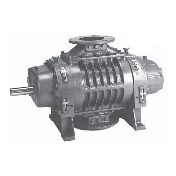
Rotary Positive Displacement Blower
Series 17/46 - Lip-Labyrinth (Air Service)
Series 57/81 - Single Envelope Gastight
Series 64/67 - Double Envelope Gastight
(obsolete 16/47 series also included in this manual)
Models
4006
4009
4012
INSTALLATION
OPERATION
MAINTENANCE
REPAIR
MANUAL
VACUUM & BLOWER SYSTEMS
TUTHILL CORPORATION
5507
5514
5509
5516
5511
5518
5520
4840 West Kearney Street, P. O. Box 2877
Springfi eld, Missouri USA 65801-2877
Tel 417 865-8715 800 825-6937 Fax 417 865-2950
http://vacuum.tuthill.com
Advertisement
Table of Contents
Troubleshooting

Related Manuals for Tuthill M-D Pneumatics PD PLUS 64/67 Series


Summary of Contents for Tuthill M-D Pneumatics PD PLUS 64/67 Series
- Page 1 4009 5509 5516 4012 5511 5518 5520 INSTALLATION OPERATION MAINTENANCE REPAIR MANUAL VACUUM & BLOWER SYSTEMS TUTHILL CORPORATION 4840 West Kearney Street, P. O. Box 2877 Springfi eld, Missouri USA 65801-2877 Tel 417 865-8715 800 825-6937 Fax 417 865-2950 http://vacuum.tuthill.com...
-
Page 2: Table Of Contents
TABLE OF CONTENTS SECTION PAGE 1. INTRODUCTION 1.1 APPLICABLE DOCUMENTATION 1.2 SCOPE OF MANUAL 2. CONVENTIONS AND DATA PLATE 2.1 GRAPHIC CONVENTIONS IN THIS MANUAL 2.2 DATA PLATE 3. LIFTING 4. DESCRIPTION 4.1 FLOW BY DIRECTION 4.2 SPECIFICATIONS 5. INSTALLATION 5.1 GENERAL 5.1.1 LOCATION 5.1.2 BLOWER AIR INTAKE... -
Page 3: Introduction
Rotary Positive Displacement Blower from Tuthill Vacuum & Blower Systems. Please examine the blower for shipping damage, and if any damage is found, report it immediately to the carrier. If the blower is to be installed at a later date make sure it is stored in a clean, dry location and rotated regularly. -
Page 4: Data Plate
2.2 DATA PLATE MAWP YEAR Tuthill Vacuum & Blower Systems MAX RPM 4840 West Kearney Street Springfield, Missouri USA 65803 READ INSTRUCTION MANUAL BEFORE OPERATION OR BODILY HARM MAY RESULT... -
Page 5: Lifting
Refer to diagrams in this manual for proper rotation and orientation in inlet and discharge. Tuthill Vacuum & Blower Systems model 4000 and 5500 Series rotary lobe blowers are positive displacement type units, whose pumping capacity is determined by size, operating speed, and differential pressure conditions. -
Page 6: Flow By Direction
Consult your Tuthill Vacuum & Blower Systems sales professional if questions arise. 4.1 FLOW BY DIRECTION... -
Page 7: Specifications
4.2 SPECIFICATIONS TABLE 1 — SPECIFICATIONS APPROXIMATE OIL CAPACITY APPROXIMATE WEIGHT FLUID OUNCES / LITERS LBS. / VERTICAL FLOW 46/81/67 HORIZONTAL FLOW 17/57/64 MODEL GEAR (DRIVE) END BACK END GEAR (DRIVE) END BACK END 17/46 57/81 64/67 4006 170 / 180 / 185 / 4009... -
Page 8: Installation
Specially ordered blowers with nonstandard construction, or with rotor end clearances greater than shown within the Assembly Clearances table, will not have the operating limits specifi ed here. Contact your Tuthill Vacuum & Blower Systems sales representative for specifi c information. - Page 9 NOTE Remove the protective covers from the shaft and inspect for damage. Carefully check to ensure that no transit damage has been sustained. If damage has occurred from shipment a claim must be fi led with the carrier immediately; preserve the shipping container for inspection by the carrier.
-
Page 10: Location
(See the Motor Drives section for more information.) Blowers from Tuthill Vacuum & Blower Systems are internally and externally treated after factory assembly and testing to protect against rusting in normal atmospheric conditions prior to installation. The maximum period of internal protection is considered to be up to 6 months under average conditions, provided closing plugs and seals are not removed. -
Page 11: Soft Foot
Repeat steps 4 and 5 on remaining feet. 5.2 SAFETY Tuthill Vacuum & Blower Systems recommends the use of relief valves to protect against excessive pressure or vacuum conditions. These valves should be tested at initial start-up to be sure they are properly adjusted to relieve at or below the maximum pressure differential rating of the blower. -
Page 12: Lubrication
5.3 LUBRICATION Every blower from Tuthill Vacuum & Blower Systems is factory tested, oil drained and shipped dry to its installation point. Both independent oil reservoirs must be fi lled to the proper level before operation. Oil reservoirs are under vacuum. -
Page 13: Filling Procedure
5.3.1 FILLING PROCEDURE See Figure 5. Recommended lubricants are shown on page 35. 1. Remove fi ll plugs or breathers from both gear end and drive end plates. 2. SLOWLY pour oil through fi ll until oil appears in the oil sight glass. Bring oil level to center of sight glass. 3. -
Page 14: Hazards Associated With Breakdown Or Ignition Of Lubrication
5.3.3 HAZARDS ASSOCIATED WITH BREAKDOWN OR IGNITION OF LUBRICATION DANGER There is a risk associated with the lubrication media breaking down and resulting in a hazardous fl uid or vapor. There may also be a hazard associated with the ignition of the lubrication media. Refer to the lubrication manufacture’s applicable instruction for safety precautions. -
Page 15: Cooling Coils (Optional)
Blowers supplied with coiling coils can also be identifi ed by the hose that connects the top of the gear (drive) end cover to the bottom of the free (non-drive) end cover. See Figures 5 and 6 for details. Tuthill Vacuum &... -
Page 16: Motor Drives
Proper gap between coupling halves must be established according to coupling manufacturers instructions with the motor armature. This will minimize the change for end thrust on the blower shaft. All direct coupled base mounted units must be re-aligned and greased after fi eld installation. 5.7 MOTOR DRIVES Two drive connections commonly used are direct drive and V-belt drive. -
Page 17: Setting V-Belt Tension
Check blower after installation and before applying power by rotating the drive shaft by hand. If it does not rotate freely, look for uneven mounting, piping strain, excessive belt tension, or coupling misalignment. Check blower at this time to insure oil was added to the reservoirs. 5.7.3 SETTING V-BELT TENSION Proper belt tension is essential to long blower life. -
Page 18: V-Belt Troubleshooting
5.7.4 V-BELT TROUBLESHOOTING PROBLEM POSSIBLE CAUSES SOLUTION Belts slip (sidewalls glazed) Not enough tension Replace belts; apply proper tension Shock load Apply proper tension Drive squeals Not enough arc of contact Increase center distance Heavy starting load Increase belt tension Broken cord caused by prying on sheave Replace set of belts and install correctly Overloaded drive... -
Page 19: Motor And Electrical Connections
1. The external lube tank is equipped with an oil fi lter which has a replaceable element. The part number for the element is 91999-1. 2. Each tank has an oil pressure relief valve which is set at the factory at 12 - 15 PSIG (80 - 100 kPa g) and normally requires no adjustment. -
Page 20: Operation
6. OPERATION 6.1 GENERAL DANGER The blower is not intended to be used with explosive products or in explosive environments. WARNING Do not operate without guards in place. WARNING Maximum operating speed: Table 2 states the maximum operating speed in RPM (rotations per minute), the maximum pressure differential, maximum vacuum and maximum temperature rise. -
Page 21: Start-Up Checklist
6.2 START-UP CHECKLIST We recommend that these startup procedures be followed in sequence and checked off ( ) in the boxes provided in any of the following cases: • During initial installation • After maintenance work has been performed • After any shutdown period •... -
Page 22: Stopping
CAUTION Do not touch hot surfaces. The upper limit of the blower operation is 400º F (205º C). Do not touch the blower while it is in operation and assure blower is cool when not in operation. CAUTION Use of a thermowell insulates the thermocouple. Invalid and delayed readings will result. -
Page 23: Operation
However, due to the wide variations in mineral content, pH, and chemical content of water that can be injected, Tuthill Vacuum & Blower Systems cannot be responsible for damage which may result should this build-up occur. Units should be inspected regularly to determine any problems. -
Page 24: Maintenance
2. For carpet cleaning applications, after the work is completed, simply allow the blower to run a few (3-5) minutes with the suction hose and wand attached. The suction hose and wand will provide enough load to the blower to evaporate the moisture quickly. ®... -
Page 25: Regular Maintenance
Personnel should have a good background of mechanical experience and be thoroughly familiar with the procedures outlined in this manual. Major repairs not covered in this book should be referred to the nearest Tuthill Vacuum & Blower Systems service representative. -
Page 26: Factory Service & Repair
7.4 FACTORY SERVICE & REPAIR With proper care, Tuthill Vacuum & Blower Systems blowers will give years of reliable service. The parts are machined to very close tolerances and require special tools by mechanics who are skilled at this work. -
Page 27: Model 4000 And 5500 Disassembly And Reassembly
8. MODEL 4000 AND 5500 DISASSEMBLY AND REASSEMBLY 8.1 DISASSEMBLY OF BLOWER WARNING Before performing any repair or replacement, disconnect and lock out power. With proper maintenance and lubrication, normal life expectancy for gears, bearings, and seals can be achieved. However, over a period of time these parts must be repaired or replaced to maintain the effi ciency of your blower. -
Page 28: Assembly Of Blower
Be sure they are in place. It is recommended that the gear end rotor shaft bearings be purchased from Tuthill Vacuum & Blower Systems, as they are specially ground to locate the rotors with correct end clearance relative to the gear end plate. - Page 29 8.2.2 GEAR END ASSEMBLY 4. Stand rotors [1] on free end in arbor press. Both keyways must be in line and point to the right. Two-lobe rotors include two keyways on each shaft. When positioning the rotors, two keyways (one on each rotor) should point in the same direction, to the right.
- Page 30 16. Check clearance between the face of the end plate and the rotor lobes. See exploded view for correct gear and clearances. If clearances are not within specifi cations, recheck parts to fi nd cause of improper clearances before proceeding. 17.
- Page 31 8.2.4 ADJUSTING ROTOR INTERLOBE CLEARANCE 32. Lay the unit down with the drive gear 2 LOBE LONG FEELER GAUGE on the left. Using feeler gauges take interlobe readings and record on RECORD A-A READING HERE each side of housing as indicated RECORD B-B READING HERE in Figure 14.
- Page 32 8.3 SPECIAL INSTRUCTIONS - 64/67 SERIES Continue assembly: A. Prepare cover (6). Place fl ange side down, install fi rst of two snap rings (78) into innermost groove. Press in fi rst of 2 ea. Mechanical seals (54A) lightly silicone outer case of seal. Press seal with carbon side down until seated against the snap ring .
-
Page 33: Troubleshooting
9. TROUBLESHOOTING Although Tuthill Vacuum & Blower Systems blowers are well designed and manufactured, problems may occur due to normal wear and the need for readjustment. The chart below lists symptoms that may occur along with probable causes and remedies. -
Page 34: Assembly Clearances
10. ASSEMBLY CLEARANCES Values shown in inches and millimeters. LOBES TO END PLATES LOBE TO HOUSING GEAR END FREE END TIP-PORT MODEL INTERLOBE .004 - .007 .006 - .011 .008 - .011 4006 .10 - .18 .15 - .28 .20 - .28 .004 - .007 .008 - .012 .008 - .011... -
Page 35: Recommended Lubricants
Blowers used in hydrogen service should use only PneuLube synthetic oil. Tuthill Vacuum & Blower Systems cannot accept responsibility for damage to seals, O-rings and gaskets caused by use of synthetic lubricants not recommended by Tuthill Vacuum and Blower Systems. -
Page 36: Special Tool Drawings
13. SPECIAL TOOL DRAWINGS FIGURE 15 — FIGURE 16 — 4000 MECHANICAL SEAL TOOL (T11549) 4000 MECHANICAL SEAL TOOL (T11549) (3.175) (3.175) .125 .125 (0.05) (0.05) .002 .002 Ø 2.103 ± .010 Ø 2.103 ± .010 53.416 ± .25 53.416 ± .25 Ø... -
Page 37: Parts Lists And Assembly Drawings
PARTS LIST FOR MODEL 4000 SERIES - 17/46 ITEM 17 / 46 PART DESCRIPTION ROTOR HOUSING END PLATE DRIVE END COVER FREE END COVER TIMING GEAR SET BEARING, DRIVE END BEARING, FREE END LIP SEAL LIP SEAL RETAINER OIL RETAINER RING OIL SLINGER DOWEL PIN DRIVE SHAFT KEY... - Page 38 PARTS LIST FOR MODEL 4000 SERIES - 57/81 ITEM 57 / 81 PART DESCRIPTION ROTOR HOUSING END PLATE DRIVE END COVER FREE END COVER TIMING GEAR SET BEARING, DRIVE END BEARING, FREE END LIP SEAL RETAINER OIL RETAINER RING OIL SLINGER DOWEL PIN DRIVE SHAFT KEY GEAR KEY...
- Page 39 PARTS LIST FOR MODEL 4000 SERIES - 64/67 ITEM 64 / 67 ITEM 64 / 67 PART DESCRIPTION PART DESCRIPTION ROTOR DOWEL PIN HOUSING CAP SCREW END PLATE OIL GAUGE DRIVE END COVER SPACER FREE END COVER O-RING, VITON TIMING GEAR SET MECHANICAL SEAL BEARING, DRIVE END DRIVE SHAFT FACE SEAL SLEEVE...
- Page 40 PARTS LIST FOR MODEL 5500 SERIES - 17/46 ITEM 17 / 46 PART DESCRIPTION ROTOR HOUSING END PLATE DRIVE END COVER FREE END COVER TIMING GEAR SET BEARING, DRIVE END BEARING, FREE END LIP SEAL LIP SEAL RETAINER OIL SLINGER DOWEL PIN DRIVE SHAFT KEY GEAR KEY...
- Page 41 PARTS LIST FOR MODEL 5500 SERIES - 57/81 ITEM 57 / 81 PART DESCRIPTION ROTOR HOUSING END PLATE DRIVE END COVER FREE END COVER TIMING GEAR SET BEARING, DRIVE END BEARING, FREE END LIP SEAL RETAINER 4 / 2 OIL SLINGER DOWEL PIN DRIVE SHAFT KEY GEAR KEY...
- Page 42 PARTS LIST FOR MODEL 5500 SERIES - 64/67 ITEM 64 / 67 ITEM 64 / 67 PART DESCRIPTION PART DESCRIPTION ROTOR DOWEL PIN HOUSING CAP SCREW END PLATE OIL GAUGE 2 / — DRIVE END COVER SPACER FREE END COVER O-RING, VITON TIMING GEAR SET DRIVE SHAFT FACE SEAL SLEEVE...
- Page 58 NOTES:...
- Page 59 NOTES:...
- Page 60 NOTES:...
-
Page 61: Declaration Of Incorporation
17/46 – Lip-Labyrinth (Air Service) 57/81 – Single Envelope Gastight 64/67 – Double Envelope Gastight The person authorized to compile the technical file is Xavier Lambert, Tuthill Corporation, Parc Industriel Wavre Nord-Avenue Vesale 30, B-1300 Wavre Belgium. Ron Rinke Director of Engineering, TVBS – Blower Systems Tuthill Vacuum &... -
Page 62: Warranty - Blower Products
WARRANTY – BLOWER PRODUCTS Subject to the terms and conditions hereinafter set forth and set forth in General Terms of Sale, Tuthill Vacuum & Blower Systems (the Seller) warrants products and parts of its manufacture, when shipped, and its work (including installation and start-up) when performed, will be of good quality and will be free from defects in material and workmanship. -
Page 63: Operating Data Form / Product Registration
NOTES: IMPORTANT All blowers manufactured by Tuthill Vacuum & Blower Systems are date coded at time of shipment. In order to assure you of the full benefits of the product warranty, please complete, tear out and return the product registration card below, or you can visit our product registration web page at: http://vacuum.tuthill.com/product_registration... - Page 64 NO POSTAGE NECESSARY IF MAILED IN THE UNITED STATES BUSINESS REPLY MAIL FIRST-CLASS MAIL PERMIT NO. 2912 SPRINGFIELD MO POSTAGE WILL BE PAID BY ADDRESSEE ATTN. CUSTOMER SERVICE TUTHILL VACUUM & BLOWER SYSTEMS PO BOX 2877 SPRINGFIELD MO 65890-2150...
Need help?
Do you have a question about the M-D Pneumatics PD PLUS 64/67 Series and is the answer not in the manual?
Questions and answers
How much oil does the 5518 model require?