
Related Manuals for Mindray DP-50T


Summary of Contents for Mindray DP-50T
- Page 1 DP-50/DP-50T/DP-50Pro/DP- 50S/DP-50Expert Digital Ultrasonic Diagnostic Imaging System Operator’s Manual [Basic Volume]...
-
Page 3: Table Of Contents
Contents Intellectual Property Statement ...................... I Responsibility on the Manufacturer Party..................I Warranty ............................II Exemptions ..........................II Customer Service Department ....................III Important Information ........................IV About This Manual ........................V Notation Conventions ........................V Operator’s Manuals ........................V Manuals on Paper ........................ - Page 4 Connecting / Disconnecting a Probe ................3-4 3.4.1 Connecting a Probe ....................3-4 3.4.2 Disconnecting a Probe ..................... 3-4 Connecting the Footswitch....................3-5 Connecting/ Removing a USB Storage Device ..............3-5 Graph/Text Printer ......................3-5 Digital Video Printer ......................3-8 Analog Video Printer ......................
- Page 5 5.8.1 Basic Procedures for PW Mode Exam ..............5-18 5.8.2 PW Mode Image Parameters ................. 5-18 5.8.3 PW Mode Image Optimization ................5-19 Anatomical M Mode (Free Xros M) ................5-23 5.10 iScape ........................... 5-24 5.10.1 Basic Procedures for iScape Imaging ..............5-24 5.10.2 Image Acquisition ....................
- Page 6 8.1.6 Deleting Comments ....................8-3 Body Mark ........................8-4 8.2.1 Body Mark Operation Procedures................8-4 8.2.2 Menu ........................8-4 8.2.3 Adding Body Marks ....................8-4 8.2.4 Moving Body Marks....................8-5 8.2.5 Deleting Body Marks ....................8-5 Patient Data Management..................9-1 Patient Information Management ..................
- Page 7 11 Setup........................11-1 11.1 System Preset ........................ 11-1 11.1.1 Region ........................11-2 11.1.2 General ........................11-2 11.1.3 Image ........................11-4 11.1.4 Application ......................11-4 11.1.5 OB .......................... 11-4 11.1.6 Key Config ......................11-5 11.1.7 Biopsy ........................11-5 11.1.8 Admin ........................11-6 11.2 Exam Preset........................
- Page 8 14 Acoustic Output ...................... 14-1 14.1 Concerns with Bioeffects ....................14-1 14.2 Prudent Use Statement....................14-1 14.3 ALARA Principle (As Low As Reasonably Achievable) ........... 14-1 14.4 MI/TI Explanation ......................14-2 14.4.1 Basic Knowledge of MI and TI ................14-2 14.4.2 MI/TI Display ......................
-
Page 9: Intellectual Property Statement
Contents of this manual are subject to change without prior notice. All information contained in this manual is believed to be correct. Mindray shall not be liable for errors contained herein or for incidental or consequential damages in connection with the furnishing, performance, or use of this manual. -
Page 10: Warranty
FITNESS FOR ANY PARTICULAR PURPOSE. Exemptions Mindray's obligation or liability under this warranty does not include any transportation or other charges or liability for direct, indirect or consequential damages or delay resulting from the improper use or application of the product or the use of parts or accessories not approved by Mindray or repairs by people other than Mindray authorized personnel. -
Page 11: Customer Service Department
Customer Service Department Manufacturer: Shenzhen Mindray Bio-Medical Electronics Co., Ltd. Address: Mindray Building, Keji 12th Road South, High-tech industrial park, Nanshan, Shenzhen, 518057,P.R.China Website: www.mindray.com E-mail service@mindray.com Address: Tel: +86 755 81888998 Fax: +86 755 26582680 Mindray DS USA, Inc. -
Page 12: Important Information
7. Important data must be backed up on external memory media. 8. Mindray shall not be liable for loss of data stored in the memory of this system caused by operator error or accidents. 9. This manual contains warnings regarding foreseeable potential dangers, but you shall always be alert to dangers other than those indicated as well. -
Page 13: About This Manual
About This Manual This operator’s manual describes the operating procedures for this diagnostic ultrasound system DP-50/DP-50T/DP-50Pro/DP-50S/DP-50Expert and the compatible probes. To ensure safe and correct operations, carefully read and understand the manual before operating the system. Notation Conventions In this operator’s manual, the following words are used besides the safety precautions (refer to "Safety Precautions"). -
Page 14: Software Interfaces In This Manual
Product Differences B-Hist Double Trace Length Keyboard Profile Dist Protective Film DP-50 × × √ √ √ DP-50S × √ × √ × DP-50T √ √ × √ × DP-50Pro √ × √ √ × DP-50Expert √ √ √ √ ×... -
Page 15: Safety Precautions
Safety Precautions Safety Classification According to the type of protection against electric shock: Externally Powered Class I Equipment + Internally powered equipment According to the degree of protection against electric shock: Type-BF applied part According to the degree of protection against harmful ingress of water: Main unit: IPX0 Probes: IPX7 Footswitch: IP68... -
Page 16: Meaning Of Signal Words
Meaning of Signal Words DANGER WARNING CAUTION In this manual, the signal words" ”, “ ”, “ ”, “NOTE” and "Tips" are used regarding safety and other important instructions. The signal words and their meanings are defined as follows. Please understand their meanings clearly before reading this manual. -
Page 17: Safety Precautions
You must use the power adapter provided with the system; otherwise electric shock may result. You can only adopt the power supply method provided by Mindray, other power supply modes (e.g. using a UPS) may result in electric shock. Connect the protective grounding conductor before turning ON the system. - Page 18 DO NOT touch the Signal I/O ports if in contact with the patient; otherwise patient injury may result. Do not use an aftermarket probe other than those specified by Mindray. The probes may damage the system causing a profound failure, e.g. a fire in the worst case.
- Page 19 19. The ultrasound system use a mains plug as isolation means to the mains power supply. Please do not set the ultrasound system in a place difficult to operate the mains plug. 20. Do not modify this equipment without authorization of the manufacture.
- Page 20 You cannot repair the system under this circumstance and must call the Mindray Customer Service Department or sales representative. There is no risk of high-temperature burns during normal ultrasound examinations.
- Page 21 If the system is used in a small room, the room temperature may rise. Please provide proper ventilation and free air exchange. To dispose of the system or any part, contact Mindray Customer Service Department or sales representative. Mindray is not responsible for any system content or accessories that have been discarded improperly.
- Page 22 The system should be powered by battery when the integrality and reliability of the protective grounding of external power supply is indeterminate. The replaceable fuse is inside the chassis. Refer replacing job to Mindray service engineers or engineers authorized by Mindray only.
- Page 23 Please use the disinfection or sterilization solution that recommended in this operator’s manual, otherwise Mindray will not be liable for damage caused by other solutions. If you have any questions, please contact Mindray Customer...
-
Page 24: Latex Alert
Latex Alert When choosing a probe sheath, it is recommended that you directly contact CIVCO for obtaining probe sheath, pricing information, samples and local distribution information. For CIVCO information, please contact the following: CIVCO Medical Instruments Tel: 1-800-445-6741 WWW.civco.com Allergic reactions in latex (natural rubber) sensitive patients may WARNING: range from mild skin reactions (irritation) to fatal anaphylactic shock, and may include difficulty in breathing (wheezing),... -
Page 25: Warning Labels
Warning Labels The warning labels are attached to this system in order to call your attention to potential hazards. The warning labels use the same signal words as those used in the operator’s manual. Read operator’s manual carefully before using the system. The name, pattern and meaning of each warning label are described as follows: No. -
Page 27: System Overview
System Overview Indications for Use The Digital Ultrasonic Diagnostic Imaging System is applicable for adults, pregnant women, pediatric patients and neonates. It is intended for use in fetal, abdominal, Intra-operative (abdominal, thoracic, and vascular),pediatric, small organ(breast, thyroid, testes, etc.), neonatal and adult cephalic, trans-rectal, trans-vaginal, musculo-skeletal(conventional, superficial), cardiac(adult, pediatric), peripheral vascular. -
Page 28: Power Supply
2.4.2 Power supply Voltage 100-240V~ Frequency 50/60Hz Input Power 1.5-0.8A 2.4.3 Environmental Conditions Operational Conditions Storage and Transportation Conditions Ambient 0℃~40℃ -20℃~55℃ temperature Relative 30%~85% (no condensation) 30%~95% (no condensation) humidity Atmospheric 700hPa~1060hPa 700hPa~1060hPa pressure Do not use this system in the conditions other than those WARNING: specified. - Page 29 Region Probe Model Category Intended Use Applied Abdominal, Pediatric, Neonatal 65C15EA Convex Cephalic, Adult Cephalic, Cardiac Body surface Pediatric Fetal, Trans-rectal, Trans-vaginal Transvaginal 65EC10EA Convex Transrectal 65EB10EA Convex Trans-rectal Transrectal Abdominal, Pediatric, Small organ (breast, thyroid, testes), Neonatal 75L38EA Linear Cephalic, Musculo-skeletal Body surface (conventional, superficial), Peripheral...
- Page 30 Needle- guided Biopsy Angle/ Probe Model Applicable Biopsy Needle Bracket Depth (±1°) Model NGB-002 40°, 50°, 60° 75L38EA 13G, 15G, 16G, 18G, 20G metal/needle un-detachable NGB-003 Metal/needle 13G, 15G, 16G, 18G, 20G un-detachable 35C20EA 11º, 23º 14G, 16G, 18G, 20G, 22G Metal/needle detachable 65EC10EA...
-
Page 31: Options
2.5.3 Options Item Free Xros M iScape View Color Power HPRF (PW should be configured) iNeedle iWorks 4D module Smart 3D iLive (4D module or Smart 3D should be configured) Smart Face (4D module should be configured) Smart OB Smart Bladder DICOM Basic (including: task management, DICOM storage, DICOM print, DICOM storage commitment, DICOM media storage (including DICOM DIR) and etc.) DICOM Worklist (Basic should be configured) -
Page 32: Introduction Of Each Unit
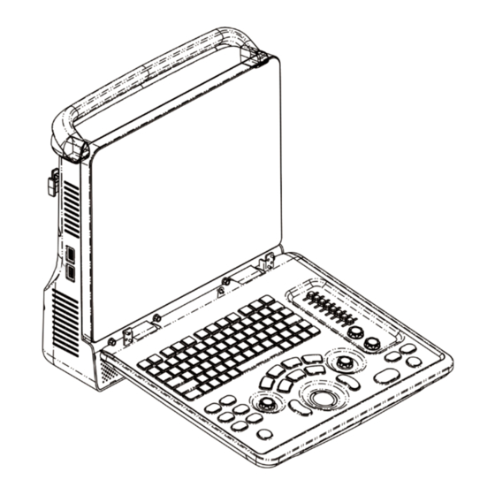
Item Model Digital Color Video SONY UP-D25MD Printer MITSUBISHI P93W-Z Black and White Video Analog Printer SONY UP-X898MD Footswitch (1-pedal; 2-pedal; 3-pedal) Parts that can be used within patient environment: Main unit Probes Footswitch Printers: SONY UP-D25MD, MITSUBISHI P93W-Z, SONY UP-X898MD ... - Page 33 Left View Rear View Bottom View System Overview 2-7...
-
Page 34: I/O Panel
Name Function Probe holder Used to place the probe Display Displays the image and parameters during scanning Control Panel Refer to the 2.6.3 Control Panel USB ports Used to connect USB devices Handle Used to carry the machine Interface panel used for inputting and outputting signals, refer I/O Panel to 2.6.1 I/O Panel. -
Page 35: Power Supply Panel
2.6.2 Power Supply Panel Name Function Power inlet AC power inlet Used for equipotential connection, that balances the Equipotential terminal protective earth potentials between the system and other electrical equipment. 2.6.3 Control Panel System Overview 2-9... - Page 36 Name Description Function Off: when system is turned off; Power button Green: when system is turned on by pressing this button. Exit Press to exit the current status to the previous status. Press to display or hide the help information on Help screen.
- Page 37 Name Description Function 3D/4D Press to enter or exit the 3D/4D status. Cursor Press to show the cursor. Trackball Roll the trackball to change the cursor position. Press to confirm an operation, same as the left- button of a mouse. Press to enter PW mode Color Press to enter Color mode...
- Page 38 Name Description Function Indicator 3 Standby indicator Standby: blinking in orange Other status: light off HDD status indicator Read/ write: blinking in green Other status: light off Indicator 4 NOTE: DO NOT move the machine when the indicator blinking in green. Otherwise the HDD may be damaged by sudden shake.
-
Page 39: Symbols
Symbols This system uses the symbols listed in the following table, and their meanings are explained as well. Symbol Description Type-BF applied part Caution Dangerous voltage Equipotentiality Power button Network port USB ports Video output Remote control port VGA signal output AC (Alternating current) Battery Status Indicator Standby indicator... -
Page 41: System Preparation
System Preparation Move/Position the System Please read and understand the safety precautions before placing the system to ensure safety for both operator and devices. 1. Switch off the power, and pull out the plug. 2. Disconnect the system from all peripherals. 3. -
Page 42: Powering On/ Off
– immediately stop scanning. If the system continues to function improperly – fully shut down the system and contact Mindray Customer Service Department or sales representative. If you use the system in a persistent improperly functioning state – you may harm the patient or damage the equipment. -
Page 43: Powering Off
If you find anything not functioning properly, this may indicate that the system is defective. In this case, shut down the system immediately and contact Mindray Customer Service Department or sales representative. NOTE: When you start the system or switch between probes, you will hear clicking sounds –... -
Page 44: Connecting / Disconnecting A Probe
When connecting or disconnecting a probe, place it in a CAUTION: proper position, to prevent the probe from falling off or becoming damaged. Only use the probes provided by Mindray. Aftermarket probes may result in damage or cause a fire. 3.4.1 Connecting a Probe... -
Page 45: Connecting The Footswitch
Connecting the Footswitch Connect the footswitch to the main unit via a USB port. Set the functions of the footswitch in the [Key Config] page. Refer to "11.1.6 Key Config" for details. Connecting/ Removing a USB Storage Device DO NOT detach an USB storage device directly; WARNING: otherwise , the ultrasound system or the USB device and/ or data stored in the device may be damaged. - Page 46 3. Power on the system and the printer. 4. Check the printer status: Enter [Setup]-> [Print Preset]->“Printer Driver” page, printers that are installed automatically will be displayed in the list with the “Status” of “Ready”. 5. Return to “Print Service” page, and select “Report Print” in the list, and set attributes in the Property box under the screen: Select the printer model from the drop-down list right to the “Printer”;...
- Page 47 6. Click [Save] to finish the installation. Tips: Click [Printer Driver]->[Printer Supported] to view the drivers of some popular printers that have already been integrated in the system. These drivers will be installed automatically. You need to check the following information to check if the auto-installation fails: Model of the connected printer is not displayed in the “Printer Driver”...
-
Page 48: Digital Video Printer
5. Click [OK] to enter the ppd installing screen: Select PPD file from media: select the path from the external media and install. Select PPD file from database: select the ppd. file integrated in the ultrasound system. 6. After the ppd. file is installed completely, enter the printer name to finish the installation. After installation succeeds, the system returns to the “Printer Driver”... -
Page 49: Analog Video Printer
(5) Set the items in the Property box and click [Save] to save the settings. Image print For DICOM image printing, refer to “10 DICOM”. Modify print service: a) Select an existed printer service in the list. b) Select the printer type in the Property box. c) Set the attribute: paper size, orientation, etc. -
Page 50: Basic Screen And Operation
3.11 Basic Screen and Operation 3.11.1 Basic Screen The following diagram maps out the different areas in the screen: Hospital name Accession# Patient Information Freeze Logo Operator Exam time icon Probe Acoustic power, MI/TI Product Mode Exam Mode Image Parameters Menu area Image area Thumbnail... - Page 51 Freeze icon The freeze icon means the image is frozen. Patient Information Displays patient name, ID, gender and age etc. Enter the patient information through the "Patient Info" screen. Or, import the saved patient data from iStation or the DICOM Worklist server.
- Page 52 Click [Return] to return to the previous menu from the sub menu. The multifunction knob can be used to operate the menu. Press the knob to open the menu; rotate the knob to navigate through the items one by one. Depending on the item types, the multifunction knob can: For a commanding item or command optional item: press the knob to directly ...
-
Page 53: Basic Operations Of Screens
None-fixing Area Position of areas illustrated here are not fixed, you can move them by the trackball within a certain area on the display. Result window The measurement result window displays the results of recently performed measurements. To move the result window: a) Place the cursor on the title of result window (you can see the cursor changes into b) Press <Set>... - Page 54 Composition Description Radio button: click to select the item. Check box: click to check or uncheck the item. Entry box: enter characters manually via the keyboard. Content Position the cursor into the box, and then enter the letters or characters.
-
Page 55: Exam Preparation
Exam Preparation Before examining a new patient, press <End Exam> to end the CAUTION: exam of the previous patient, update the patient ID and information, to avoid mixing data of the next new patient. Start an Exam You can start a patient exam in the following situations: New patient information: to start a new patient exam, enter the patient information ... - Page 56 You can also change the cursor position by <Tab>, <Enter> or up/down controls Information includes: 1. General information Name Enter patient name through the keyboard. Characters of A through Z and 0 through 9 and “.” are allowed. “\”, “^”, “=” and “, ” are not permitted. Patient ID ...
- Page 57 NOTE: When you enter the date manually, please enter it in the format as that of the system. 2. Exam Type Exam application type You can select among: ABD (Abdomen), OB (Obstetrics), GYN (Gynecology), CARD (Cardiac), VAS (Vascular), URO (Urology), SMP (Small Part), PED (Pediatrics), and BREAST.
- Page 58 Exam Type Information Description Last menstrual period Gravida Times of pregnancy. Para Times of delivery (Gynecology) Ectopic Times of abnormal pregnancy. e.g. extrauterine pregnancy Aborta Times of abortion Height Weight BSA (body After the height and weight are inputted, the system will surface automatically calculate the BSA based on the formula which CARD...
-
Page 59: Retrieve Patient Information
4.2.2 Retrieve Patient Information 4.2.2.1 iStation The patient data can be obtained in iStation from the system hardware or USB memory device. You can enter the searching conditions for the patient. 1. To enter iStation screen (the screen is shown as follows): Press <iStation>... - Page 60 Button Function Description Review Click to enter the Review screen. Image Patient Click to enter the Patient Info screen. Info Review Click to enter the Diagnostic Report screen. Report Delete Click to delete the selected record. Exam Backup Click to export the selected patient data to media supported. Exam Restore Click to import the patient data from an external media.
-
Page 61: Select Exam Mode And Probe
Enter patient ID, patient name, accession #, the system affords the result in real-time. Or select the keyword type, enter the keywords and then click [Query] to search. To reset the criteria, click [Clear] button. 3. Select the desired patient from the list. Click [Start Exam], the patient information is imported into the system and then an ... -
Page 62: Dual Probe Switching
To save the image parameters for the current exam mode quickly: Click [QSave] in the Probe & Exam page or click the user-defined key for QSave to save the image parameters in the current image mode as presets. A dialogue box pops up to prompt you the operation will cover the current image preset data. -
Page 63: Selecting Imaging Mode
5. Click [Save] to confirm the setting and exit the dialog box. 6. Press the defined key on the control panel for [Dual Probe] function, both the S plane and T plane image of the probe will be displayed on the screen. Press the user-defined key to switch between the two windows to activate the current window. -
Page 64: Pause & End An Exam
If you want to continue an exam which data lies in an external memory database, you have to first allow the system to load the patient data to the system’s patient database. Pause & End an Exam 4.6.1 Pause and Exam ... -
Page 65: Image Optimization
Image Optimization The images displayed in this system are only reference for WARNING: diagnosis. Mindray is not responsible for the correctness of diagnostic results. It is the responsibility of the clinician, who performs the exam, to capture the correct diagnostic results. -
Page 66: Basic Operations
Create a new exam data (using current image parameter setting): Enter the name in the box after the “Save As” to assign a name for a user-defined exam mode, and click [Create] to save the current image parameters, measurements, comments, body mark settings to the exam mode. -
Page 67: B Mode Parameters
5.4.2 B Mode Parameters In B mode scanning, the image parameter area in the upper left corner of the screen displays the real-time parameter values as follows: Display Parameter Frequency Depth Gain Frame Rate B IP B Dynamic Range 5.4.3 B Mode Image Optimization Gain Description To adjust the gain of the whole receiving information in B mode. - Page 68 Effects Adjust the signal gain for the certain image area to get a balanced image. Frequency Description This function is used to select the operating frequency of the current probe, the real-time value of which is displayed in the image parameter area in the upper left corner of the screen, where “F”...
- Page 69 The FOV position/range is available only for the convex probe. Click [ExFov] on the image menu to turn on/off the function. ExFov For linear probes, the ExFOv function displays as trapezoid imaging. For convex probes, the ExFOv function displays as extending the scanning angle.
- Page 70 Persistence Description This function is used to superimpose and average adjacent B images, so as to optimize the image and remove noises. Operation Adjust through the [Persistence] item in the menu; The system provides 8 level of frame average adjustment, the bigger the value the stronger the effect.
- Page 71 Description IP is a combination of several image processing parameters, which is used for a fast image optimization, the real-time group of which is displayed in the image parameter area in the upper left corner of the screen. The IP combination parameters include dynamic range, iClear, persistence, and smooth.
-
Page 72: M Mode
γ Description The γ correction is used to correct non-linear distortion of images. Operation Click [γ] on the image menu to adjust. The adjusting range is 0-3, increase the value, the image turns dark. Gray Invert Description Reverse the polarity of the image. Operation Click [Gray Invert] to turn on or off the image inversion. -
Page 73: M Mode Parameters
5. Adjust the image parameters to obtain optimized images. 6. Perform other operations (e.g. measurement and calculation) if necessary. 5.5.2 M Mode Parameters In M mode scanning, the image parameter area in the upper left corner of the screen displays the real-time parameter values as follows: Display IP 6... - Page 74 Operation Adjust it through [Frequency] on the image menu, wherein “H” means the harmonic frequency. Values of frequency vary depending upon the probe types. Select the frequency according to the detection depth and current tissue characteristics. Effects The higher the frequency the better the near field resolution but the worse the force of penetration.
- Page 75 Effects Speed changing makes it easier to identify disorders in cardiac cycles. Description IP is a combination of several image processing parameters ,which is used for a convenient image optimization. The IP combination number is displayed on the image parameter area on the right part of the screen. The M IP combination parameters include dynamic range and M soften.
- Page 76 Operation Select among the maps through the [Gray Map] item in the menu. The system provides 25 gray maps to be selected among. Impacts The function is available in real-time imaging, freeze or cine review status. Edge Enhance Description This function is used to increase image profile, so as to distinguish the image boundary.
-
Page 77: Color Mode Image Optimization
Color Mode Image Optimization The Color mode is used to detect color flow information, and the color is designed to judge the direction and speed of blood flow. Generally, the color above the color bar indicates the flow towards the probe, while the color below the color bar indicates the flow away from the probe;... - Page 78 Effects Increasing the gain will increase the flow signal presented as well as noise, while the signals may be missing when the gain is adjusted too low. Steer Description The feature is used to adjust the ROI of color flow of different angles with immobility of the linear probe.
- Page 79 Priority Description This function is used to set levels of the flow display, to display the grayscale signal or color signal. Operations Click the [Priority] item on the image menu to select the value. The adjusting range of the priority is 0-100%. The higher the value, color signals are prior to be displayed;...
-
Page 80: Power Mode Image Optimization
B/C Align Description To set and constrain the maximum width of the B mode image to that of the Color ROI. Operations Turn on or off the function through the [B/C Align] item on the image menu. Impacts Frame rate increases when the function is turned on. Dual Live Description This function is used to display B image and Color image synchronously. -
Page 81: Power Mode Image Parameters
2. Click [Power] on image menu to enter B + Power mode. Roll the trackball to change position of the Region of Interest (ROI) and press the <Set> key to set. Roll the trackball to change the size and position of ROI. 3. -
Page 82: Pw Doppler Mode
Operations Click the [Dynamic Range] item on the image menu to adjust the dynamic range. Effects Increasing dynamic range will lead to higher sensitivity to low-power signals, thus enhances the range of signals to display. PW Doppler Mode PW (Pulsed Wave Doppler) mode is used to provide blood flow velocity and direction utilizing a real-time spectral display. -
Page 83: Pw Mode Image Optimization
When you adjust the depth of the B mode image, related changes will occur in PW mode image as well. 5.8.3 PW Mode Image Optimization Gain Description This function is intended to adjust the gain of spectrum map. The real-time gain value is displayed in the image parameter area in the upper right corner of the screen. - Page 84 Effects This feature is used to steer the direction of the beam so as to change the angle between the beam and flow direction with immobility of the linear probe. Values of steer angles vary by probe. Steer is available only for linear probes Invert Description This function is used to set the display manner of spectrum.
- Page 85 HPRF Description HPRF mode is used when detected velocities exceed the processing capabilities of the currently selected PW Doppler scale, or when the selected anatomical site is too deep for the selected PW Doppler scale. Operations Turn on or off the function through the [HPRF] item on the image menu. Effects HPRF enhances the range of detecting high-velocity flow.
- Page 86 Auto Calculation Description This function is used to trace the spectrum and calculate parameters of PW image, and the results of which are displayed in the result window. Auto Turn on or off the auto calculation function through the [Auto Calc] item on the Calculation image menu.
-
Page 87: Anatomical M Mode (Free Xros M)
Quick Angle Description To adjust the angle faster, in increments 60°, and the real-time value of which is displayed on the right part of the spectrum map. Operations Click the [Quick Angle] item on the image menu. There are 3 angles for quickly adjustment: -60°, 0°, and 60°. Anatomical M Mode (Free Xros M) Anatomical M Mode and Color Anatomical M mode images are CAUTION:... -
Page 88: Iscape
Operations Press <Set> to hide or show between the M-mark lines and press <Cursor> to show the cursor. The activated M-mark line will be green. Adjustment of the M-mark Line Description To adjust the position and angle of the M-mark line. Operations Position Adjustment ... -
Page 89: Image Acquisition
Click the [iScape] item on the image menu or press the user-defined key of iScape on the control panel. (You can preset a user-defined key via [Setup] -> [System Preset] -> [Key Config].) 3. Optimize the B mode image: In the acquisition preparation status, click the menu title to enter the B mode image optimization. -
Page 90: Iscape Viewing
Always keep the probe perpendicular to the skin surface. Don’t rock, rotate or tilt the probe during the scan. The system accommodates a reasonable range of motion velocity. Don’t make abrupt changes in speed of motion. Deeper scans generally require reduced acquisition speed. ... -
Page 91: Cine Review
5.10.3.5 Evaluate Image Quality Many variables may affect the overall image quality. It is important to evaluate the image content and quality before an image is used for diagnosis or measurements. NOTE: iScape panoramic imaging is intended for well-trained ultrasound operators or physicians. -
Page 92: Note Before Use
5.11 3D/4D 5.11.1 Note before Use 5.11.1.1 Smart 3D Image Quality Conditions NOTE: In accordance with the ALARA (As Low As Reasonably Achievable) principle, please try to shorten the sweeping time after a good 3D imaging is obtained. The quality of images rendered in the Smart 3D mode is closely related to the fetal condition, angle of a B tangent plane and scanning technique. -
Page 93: Overview
NOTE: 1. A region with qualified image in B mode may not be optimal for Smart 3D imaging. E.g. adequate AF isolation for one section plane doesn’t mean the whole desired region is isolated by AF. 2. More practices are needed for a high success rate of qualified Smart 3D imaging. - Page 94 image Cut plane ROI size and position Roll the trackball to change the ROI size and position, press the <Set> key to toggle between setting the size (dotted line) and position (solid line, with a small box at each corner of ROI).
- Page 95 View Direction a. Up/Down b. Down/Up c. Left/Right d. Right/Left e. Front/Back f. Back/Front Wire cage When you view a Smart 3D image on the display monitor, it’s sometimes difficult to recognize the orientation. To help, the system displays a three-dimensional drawing to illustrate the orientation.
-
Page 96: Static 3D
Wire Cage The ultrasound images are provided for reference only, not for CAUTION: confirming a diagnosis. Please use caution to avoid misdiagnosis. 5.11.3 Static 3D Static 3D provides single frame image acquisition of 3D images. During scanning, the probe performs the scanning automatically. The probe D6-2EA supports the static 3D. - Page 97 Draw a circle here ROI cover this area Cross cursor on the VOI curve For setting the ROI, be sure to: Set the ROI on the 2D image with the largest section area of the fetal face. Set the ROI a little larger than the fetal head. ...
- Page 98 5.11.3.2 Static 3D Acquisition Preparation Description of parameters: Type Parameter Description Function: to set the range for imaging. Angle Range: 10-70°. Parameter Function: to adjust the image quality by changing the line adjusting density. Image quality can affect the imaging speed: the Quality better the image quality, the longer the time.
- Page 99 Window A is blue, and the lines (representing MPR A) displayed in the other two windows are also blue. Window B is yellow, and the lines (representing MPR B) displayed in the other two windows are also yellow. Window C is orange, and the lines (representing MPR C) displayed in the other two ...
- Page 100 View Direction a. Up/Down b. Down/Up c. Left/Right d. Right/Left e. Front/Back f. Back/Front Adjust VOI VOI On The VR image displays VOI information. 1. In image viewing status, click [VOI] to turn it to “On.” 2. Roll the trackball to adjust the VOI position, size and curved VOI, and press <Set> to switch between the adjusting status.
- Page 101 Image Rendering Parameters In image viewing status, render the image by adjusting the relevant parameters. Render setting parameters description: Click [VR/MPR] on the screen to select VR or MPR parameter adjustments. When [VR] is highlighted in green, parameter adjustment is performed on the VR ...
- Page 102 Reset Curve Parameter Description Reset Ori To reset the volume rotation, shifting and zooming to its original status. Reset Curve To reset the curve to its original status. Reset All To reset the volume to its original orientation and original parameters. ...
- Page 103 To rotate along the Z-axis: rotate the <PW> button on the control panel clockwise and the image rotates right along the Z-axis. Rotate the button counter-clockwise and the image rotates to the left. Auto rotation (1) In 3D viewing mode, click the [Auto Rot.] tab on the screen. The system enters the auto rotation preparation state.
-
Page 104: Smart 3D
a) Press <Set> to fix the rectangle's position, roll the trackball to change the size, and press <Set> again to finish drawing the rectangle. b) Move the cursor to the region you want to cut and press <Set> again to cut. To undo the last cutting, Click [Undo] on the screen. - Page 105 1. Select the appropriate probe (non-4D probe) and exam mode. Make sure there is sufficient gel on the probe for scanning. 2. Obtain a 2D image. Optimize the image as described in the Static imaging procedure. 3. Press <3D/4D> to enter the Smart 3D imaging preparation status, and define the ROI as well as the curved VOI.
- Page 106 Description of parameters: Parameter Description Function: select the image acquisition method. Selection: Rocked, Linear. Linear mode: during the sweep, the probe must be kept parallel. The scanning speed should be constant. Rocked mode: in this mode, the probe must be moved to a position where you Method can clearly see a middle cut of the object you want to scan and render.
-
Page 107: Ilive
5.11.4.4 Image Saving and Reviewing in Smart 3D It is similar to the saving and reviewing in Static 3D mode. 5.11.5 4D 4D provides continuous, high-volume acquisition of 3D images. During scanning, the probe performs the scanning automatically. 4D image acquisition operations are similar to those of Static 3D. The only difference is that in static 3D mode, only a single frame 3D image is captured, while in 4D mode, continuous, high-volume acquisition of 3D images is provided. -
Page 108: Ipage
iLive is an option, and is available under Smart 3D, Static 3D and 4D modes. To use the iLive function, you must configure the Smart 3D module or the 4D module. To Activate iLive 1. Enter 3D/4D image viewing status, or double-click the saved 3D/4D cine file in the iStation or Review screen. - Page 109 5.11.7.2 iPage Basic Functions and Operations <1> A plane <2> B plane (the current <3> C plane reference image) <4> Y-axis <5> X-axis <6> Central section line (Current active section line) <7> Section line <8> Space between two <9> Image parameter planes <10>...
-
Page 110: Smart Face
Slice position (to the central slice): displayed in the top-left corner of each image, indicating the position of each image (such as -7 mm, -3 mm, 3 mm, 8 mm). Coordinate axis: indicated on the three A, B, C reference images. Correspond to the ... - Page 111 2. Click [SmartFace] to enter the function and the system adjust fetal face angle (fetal head facing up and face is at the front with [Direct] to be up/down) automatically and remove the shading obstacle data. Parameter adjusting Parameters under Smart Face are similar to those under Static 3D mode. FaceContact ...
-
Page 113: Display & Cine Review
Display & Cine Review Image Display 6.1.1 Splitting Display The system supports dual-split (B/B) and quad-split (4B) display format. However, only one window is active. Dual-split: press <Dual> key on the control panel to enter the dual-split mode, and using <Dual>... -
Page 114: Freeze/ Unfreeze The Image
6.1.2.2 Pan Zoom Procedures: 1. Enter Zoom: Freeze the image, press <Depth/Zoom> knob on the control panel to light the Zoom indicator. Image-in-image is displayed. 2. Rotate <Depth/Zoom> knob to change the magnification factor among 0.8-10. 3. Exit: Press <Depth/Zoom>. ... -
Page 115: Cine Review
In freeze mode, the system supports imaging mode switching between the sub- modes (only for the activated window). The imaging mode and parameters of an unfrozen image is the same as the corresponding one that before frozen; but the display format is the same as the one before unfrozen. -
Page 116: Cine Review In 2D Mode
6.2.2 Cine Review in 2D Mode Manual cine review After entering the cine review of 2D mode, rolling the trackball will display the cine images on the screen one by one. If you roll the trackball to the left, the review sequence is reversed to the image-storing sequence, thus the images are displayed in descending order. -
Page 117: Linked Cine Review
Roll the trackball to the left, the review progress slider moves to the left, the images moves to the right, and the earlier stored images are invoked. Whereas, roll the trackball to the right, the review progress slider moves to the right, and the images move to the left, the recently stored images are invoked. -
Page 118: Frame Compare
b) In Review screen, click [History] to select the exam; click to select the image to be compared in different exams, and click [Image Compare]. 6.3.2 Frame Compare Freeze the image in B/C mode, click [Frame Compare] in “Cine” page on the image menu to enter frame compare mode. -
Page 119: Preset
Start a new exam for the same patient. Switching the probe (if the cine memory is split, only the cine memory corresponding to the currently activated window is cleared) Changing the exam condition (if the cine memory is split, only the cine memory ... -
Page 121: Measurement
Measurement There are general measurement and application measurement. You can perform measurements on a zoomed image, cine reviewing image, real-time image, or a frozen image. For measurements details, please refer to the [Advanced Volume]. Be sure to measure areas of interest from the most optimal WARNING: image plane... -
Page 122: M General Measurements
Measurement Tools Function Volume The volume of a target. The length of two line segments, which are perpendicular to each Cross Line other. Parallel Line The distance between each pair of parallel lines in a sequence. Trace Length (Trace) Measures the length of a curve on the image. Trace Len (Spline) Measures the length of a curve on the image. -
Page 123: Application Measurement
Measurement Function Tools N intervals (n≤8) are measured to calculate a PW mode derived HR value in Beats Per Minute (BPM). On the Doppler mode image, velocity and PG (pressure gradient) of a D Velocity point on the Doppler spectrum waveform are measured. Velocity and time interval between two points are measured to calculate Acceleration speed difference and acceleration. -
Page 124: Measurement Accuracy
Measurement Accuracy Table 1 Error of 2D Images Parameter Value Range Error Within ±3%; or when the measured value is less Distance Full screen than 40 mm, the error is less than1.5 mm. Within ±7%; or when the measured value is less Area (Trace) Full screen than 16 cm... -
Page 125: Comments And Body Marks
Comments and Body Marks Comments Comments can be added to an ultrasound image to bring attention, notate or communicate information observed during the examination. You can add comments to: zoomed image, cine review image, real-time image, frozen image. You can type the character as comments; insert the pre-defined comments from the comment library;... -
Page 126: Adding Comments
Please refer to “11.5 Comment Preset” for comment preset for the specific exam mode. ABC Display Click [ABC Display] to display or hide the added comments. Assign the user-defined key for the function in “[Setup]-> [System Preset]->“Key Config” ”. Set comment language ... -
Page 127: Moving Comments
Adjust the position and orientation of the arrow: roll the trackball to the desired position and use the multifunctional knob to change the orientation in 15° increments. Click [Arrow Size] on the menu to change the arrow size: 3. -
Page 128: Body Mark
NOTE: When no object is selected, pressing the <Clear> key will clear all comments and all measurements calipers. After powering off, the system will clear all comments on the image. Body Mark The Body Mark (Pictogram) feature is used for indicating the exam position of the patient and transducer position and orientation. -
Page 129: Moving Body Marks
8.2.4 Moving Body Marks You can move the body mark graphic to any desired position within the image area. 1. Roll the trackball to move the cursor onto the body mark. The cursor changes into indicating you can move the pictogram to a new position. 2. -
Page 131: Patient Data Management
External storage media is recommended for image archive. The system patient database space is limited, please back up or clear patient data in time. Mindray is not responsible for lost data if you DO NOT follow suggested backup procedures. Patient Information Management 9.1.1... -
Page 132: Image File Management
Image File Management You can store the image files either in the patient database in the system, or to external memory devices. For a save image, you can perform operations like image reviewing, analyzing and demonstration (iVision). 9.2.1 Storage Media System supported memory media including: System hard disk ... -
Page 133: Saving Images To The System
Set single frame export format Format You can select the image export format in the Send To dialogue box. NOTE: Compression in a JPEG format may result in image distortion. Set cine saving length For details, please refer to “6.5 Preset”. 9.2.4 Saving Images to the System ... -
Page 134: Quickly Saving Full Screen Image To The System
(3) Press the user-defined key to save the cineloop. 9.2.6 Quickly Saving Full Screen Image to the System This function can save the current full screen image to the system with the image in real-time status. 1. Set the user-defined key through the path: [Setup](by pressing <Setup>)→ [System Preset]→... - Page 135 To exit Review: Click [Exit] on the Review screen; or, Press <ESC> or <Review> again. Basic operations Move the cursor onto an exam item in the Exam History area and press <Set>. The selected item is highlighted. Click [Info] or [Report] to view patient information or report. Double-click a thumbnail to view and analyze an image.
-
Page 136: Ivision
[Deselect All]: after clicking the [Select All], the button changes into [Deselect All], you can cancel all the selections by clicking [Deselect All]. [Send To]: click to send the selected image to other location, DICOM server, printer and etc. Or, select the image and click [Delete]: click to delete the selected image. - Page 137 Demonstration item The demonstration items are the image files in the formats that the system supports. You can add the exam data in patient database or system supported image files and folders to demonstration list. For files and folders in demonstration list, the images in the directory and subdirectory are played one by one, and the system will automatically jump over the files that can’t be opened.
-
Page 138: Sending Image File
Option of Demo You can choose whether to repeat the demonstration or exit after a demonstration is completed. 9.2.10 Sending Image File On the image screen, select a stored image thumbnail, click (Send To) on the right corner of the image, the image can be sent to the external device, DVD recorder, DICOM storage server, DICOM print server, system connected printer, iStorage, MedSight and etc. -
Page 139: Patient Data Management (Istation)
In the iStation screen, click ; or, in Review screen, click [Send To] to send patient data to an external memory device, you can choose if reports are exported with images. See the figure below. To export the report: (1) Check “Export Report” on the screen. (2) Click [OK] to confirm. -
Page 140: Searching A Patient
Viewing Patient Information Data Source Select the data source of patient data, the system patient database is default. Patient List Display patient information, exam mode, number of images and cines, exam state, backed up or not. New Exam: After you select a patient data or exam in the iStation screen, click the [New Exam] to enter the Patient Info screen, where you can select a new exam mode and click [OK] to begin a new exam. -
Page 141: Patient Data View & Management
Select “Find in results”, the system will do searching based on the last searched results. 9.4.2 Patient Data View & Management Select the desired patient information in the list. The following menu pops up: Review Select an exam of a patient, click to enter Review screen. -
Page 142: Backing Up And Erasing Files Through Dvd Drive
Send images to USB devices, DVD drive, DICOM storage server, DICOM printer, video printer, text/ graph printer or iStorage server. Send images with report to USB devices, DVD drive or iStorage server. Format transfer is available when sending images to USB devices, DVD or ... - Page 143 (2) Select the data to be backed up, click the screen (in iStation or Review). Select the target drive in the Send To or Back Up Patient Record dialogue box. (3) Click or [OK] to start writing with the symbol displays (4) After the writing process is completed, click to pop up the Disc Option dialogue box, and select [Eject] to eject the CD/DVD.
-
Page 144: Patient Task Manager
Patient Task Manager Click at the lower right corner of the screen to pop up the following dialogue box: Including: Storage Task: displays the DICOM storage task. DICOM Print Task: displays the DICOM print task. Media Storage Task: DICOM media storage task(including disc and USB devices) ... -
Page 145: Access Control
Delete Click [Cancel] to cancel the selected task. Retry Click [Retry] to retry the failed task. When the printer ran out of ink or paper, tasks in print list will be paused. Click [Retry] to continue the paused print task. ... -
Page 146: System Login
9.7.3 System Login If [Enable User Account Control] is selected, you can access the data in the system only after you login the system. You need to enter user name and password in the following cases: Before entering the system ... - Page 147 2. Click [Add] to enter the following page. 3. Enter the user name(you are not allowed to enter the same name or modify the name already exist). 4. Enter user name and the password. 5. Set the user role in the drop-down list: administrator or operator. 6.
-
Page 148: Modify Password
9.7.5 Modify Password The system administrator can modify password of all users. The administrator password by factory is empty. You can set the password for it. The operator can only modify his/her own password. To modify the password, the user has to login the system first. There are two ways to modify password: modify it on “Admin”... -
Page 149: Dicom
DICOM NOTE: Before using DICOM, please read the electronic file DICOM CONFORMANCE STATEMENT along with the device. This chapter is confined to the preset, connection verification and DICOM services of the DICOM-configured ultrasound machine, not including SCP configurations like PACS/ RIS/ HIS. The DICOM package is optional, so the description here is only applicable for the system configured with the DICOM package. -
Page 150: Dicom Preset
1. Press <Setup> to enter the [Setup] menu. 2. Select [Network Preset]. 3. Local TCP/ IP preset items are described as follows: Name Description Current Net Adapter To select network connection mode. DHCP DHCP: IP address will be automatically obtained from DNS server; / Static Static: you need to enter the IP address. - Page 151 3. Preset local DICOM properties and DICOM server. Localhost DICOM Service Property Name Description Application entity title of the ultrasound system. AE Title The AE title here should be the same with the one of the acceptable SCU set in the server. DICOM communication port, which should be the same with the one Port in the server.
- Page 152 Name Description [Set DICOM Service] Click to enter DICOM service preset, see “10.1.3 DICOM Service”. [Delete] Click to delete the selected server (s) in the device list. Note: If the currently entered name has already existed, the system will pop up: “The server ...
- Page 153 DICOM storage setting items are described as follows: Name Description After you set the server (s) in DICOM Server Setting, the name Device (s) will appear in the drop-down list, select the name of the storage server. Service Name Default is xxx-Storage, and it can be modified. Application Entity title, Here, it should be consistent with that of AE Title the storage server.
- Page 154 Name Description [Add] Add the DICOM service to the service list. [Cancel] Click to cancel the parameter setting. Select an item in the service list, change the parameters in the [Update] above area, and click [Update] to update the item in the service list.
- Page 155 DICOM print setting items are described as follows: Name Description After you set the server (s) in DICOM Server Setting, the Device name (s) will appear in the drop-down list, select the name of the print server. Service Name Default is xxx-Print, and it can be modified. Application Entity title.
- Page 156 Name Description Specify quantity of printed files,e.g. STANDARD\2, 3 Display Format indicates 6 images are printed for each page. Specify print medium: Paper, Clear Film, Blue Film. Medium Type Specify whether you want a trim box to be printed around Trim each image on the film: Yes or No.
-
Page 157: Verify Connectivity
DICOM Worklist service parameters are similar to those described in DICOM Storage Preset, please refer to “10.1.3.1 Storage” for details. 10.1.3.4 MPPS Preset 1. On DICOM Service screen, click [MPPS] page tab to enter the MPPS page: 2. Select device, enter the right AE Title, port, etc. 3. -
Page 158: Dicom Service
The server supports the verification, but this function is not activated. Please check if the verification function is activated. Note: Not all the SCPs can support verification; please consult SCP belongings to confirm whether SCP can support this service. If not, the verification won’t pass. 10.3 DICOM Service If the system is configured with DICOM modules, and connected to the relevant DICOM servers, after verifying connection, you can perform storage, print, Worklist, MPPS, storage... -
Page 159: Dicom Print
a) Open Key Config page via “[Setup] → [System Preset] → [Key Config]”. b) Assign functions to the desired keys: in Key Config page, select a free key or footswitch at the left side, then select the corresponding key on the right side: c) Click [Save] to confirm the preset and exit. -
Page 160: Dicom Worklist
(3) Click [OK] to send print task. To print image for storage after an exam ends (1) Open “[Setup] → [System Preset] → [General]”, and then check (2) Set a default print server. a) Enter the DICOM Service Preset screen via “[Setup]→ [DICOM Preset] → [DICOM Service]”. -
Page 161: Mpps
c) The scheduled patients, which meet the criteria, are displayed in the lower part of the screen. d) After the first query, you can perform the second query based on the preview results. The scheduled patients in the list will update in real time. (4) Select the desired patient record in the displayed patient list, and Select the desired patient and click [Start Exam], the patient information is imported into the system and then an exam is started. -
Page 162: Query/Retrieve
(3) Click to select “DICOM” in the “Target” box on the left side, then select the DICOM storage server in the “Storage Server” box on the right side. (4) Click [OK] to start sending. The system will send all the images stored in the exam record to the storage server, meanwhile, it will send storage commitment to the storage commitment server. -
Page 163: Dicom Media Storage
3. Select the server in “Server and Service” area (both the source and the destination). 4. Enter the query information, such as Patient ID, Patient Name, Accession #, Exam Date, or key words. Click [Clear] to empty the entered query information. 5. -
Page 164: Structured Report
3. Select the destination, and select DICOM format. 4. Set whether to remove patient exam data or only images from the local hard disk. 5. Click [Backup] to begin storage. If the backup succeeded, there will be a tick marked in the Backup list in iStation screen; otherwise, no tick is marked. -
Page 165: Dicom Task Manager
Send image and structured report for storage in iStation screen (1) Select “Attach SR When Store Images” in the DICOM Storage preset page, for details; please refer to “10.3.1 DICOM Storage”. (2) Create new patient information or load scheduled the patient information. (3) Perform measurements. -
Page 167: Setup
CD/DVD or USB memory devices. When the setup data is changed, be sure to save the preferences CAUTION: according to the methods described in this chapter. Mindray is not responsible for the loss of the setup data. To enter Setup: Press the <Setup>... -
Page 168: Region
11.1.1 Region Open the Region page via [Setup]-> [System Preset]-> [Region], as shown in the figure below. Item Description To set the hospital relevant information like name, address, telephone Hospital Information and so on. To select a language for the system. Language The system will restart automatically after you change the language and return from the Setup menu. - Page 169 Type Item Description To select if to display the following patient information Patient Banner on the image banner: Gender, Age, Operator, ID, Display Content Name, Hospital Name Patient Info H&W Unit To set the unit for patient height and weight. Surface Formula To set the surface formula.
-
Page 170: Image
Type Item Description Brightness/Contrast Load the factory data of the display brightness and Load Factory contrast. 11.1.3 Image Open the Image Preset page via [Setup]-> [System Preset]-> [Image], as shown in the figure below. Type Item Description Reset Config Probe To set the default probe model for the system. -
Page 171: Key Config
11.1.6 Key Config Open the page via [Setup]-> [System Preset]-> [Key Config], as shown in the figure below. Key function setting You can set the functions for <Print>, <Save1>, <Save2>, F1 key and footswitch. To assign a function to a key: (1) Click to select the desired key in the Key Function column at the left side of the page. -
Page 172: Admin
Bracket To select the default needle-guided bracket for the probe. Parameter Press to display the biopsy guideline. 11.1.8 Admin Open the Admin page via [Setup]-> [System Preset]-> [Admin]. For details of access control, please refer to “9.7 Access Control”. 11.2 Exam Preset Open [Setup]->... -
Page 173: Measure Preset
11.3 Measure Preset For measurements details, please refer to the Advanced Volume. 11.4 Body Mark Preset In order to accommodate your workflow – numerous preferential settings can be captured in Body Mark Preset. This function is to preset, body marks in each exam type, or user-defined body marks. -
Page 174: Comment Preset
the multifunctional knob to change the angle, and press <Set> to confirm the orientation of the probe. 7. Select the body mark in Selected Items and click [Default], and then the body mark will be marked with a tick ”√”. 8. -
Page 175: Print Preset
Remove item (from the library or user-defined) in the Selected Items list: Select an item in Selected Items list, and click [<] to remove it to the Available Items list. Click [<<] to remove all items in Selected Items. Delete a user-defined item in the Available Items box. -
Page 176: Network Preset
Check the printer attribute. For details about DICOM print, please refer to “10 DICOM”. 11.7 Network Preset For Local TCP/IP preset and DICOM preset, please refer to “10.1 DICOM Preset”. 11.7.1 iStorage Preset The iStorage screen is as follows: Name Description Service Name... -
Page 177: Medsight Preset
Tips: Every trial option can be used only once. Please contact Mindray Customer Service Department or sales representative for details. 11.8.2 Probe Check This function enables users to check if a transducer element is in malfunction, so as to evaluate the transducer performance. -
Page 178: Other Settings
Notes: Probe check is provided for reference only, not for confirming a diagnosis. Each time a transducer is connected to the main system or activated, the users are recommended to implement probe check of transducer performance. Before probe check, make sure the probe is clean and not being used for scan. Probe check should be performed on B mode. -
Page 179: Probes And Biopsy
Probes and Biopsy 12.1 Probe The system supports the following probes: Probe Model Illustration 35C50EA 65C15EA 65EC10EA 75L38EA Probes and Biopsy 12-1... - Page 180 Probe Model Illustration 75L53EA 10L24EA 65EB10EA 35C20EA 65EC10ED 75LT38EA 12-2 Probes and Biopsy...
-
Page 181: Name And Function Of Each Part Of The Transducer
Probe Model Illustration D6-2EA Note: For details of storage time and condition for disinfected probes or sterilized probes and brackets, please refer to Technical standard for Disinfection of Medical and Health Structures 12.1.1 Name and Function of Each Part of the Transducer Basic structures and functions of all probes listed above are similar, and are described as follows. -
Page 182: Orientation Of The Ultrasound Image And The Transducer Head
Name Function Used to connect the transducer to the ultrasonic diagnostic <4> Transducer connector system. This locks the connector to the ultrasonic diagnostic <5> Lock handle system. The probes’ structure marked <2> in the figure above may vary with the matched needle- guided brackets. -
Page 183: Operating Procedures
Orientation mark Mark 12.1.3 Operating Procedures This section describes general procedures for operating the transducer. The proper clinical technique to be used for operating the transducer should be selected on the basis of specialized training and clinical experience. Probes and Biopsy 12-5... - Page 184 Procedures for operating (with biopsy function) 12-6 Probes and Biopsy...
- Page 185 Procedures for operating (with no biopsy function) Inspection before examination Connection to the ultrasonic diagnostic system Examinations Disconnection to the ultrasonic diagnostic system Wiping off the ultrasound gel Thoroughly cleaning the transducer Drying the transducer Disinfecting the transducer Rinsing the transducer Drying the transducer Inspection after use Storage...
-
Page 186: Utilizing The Transducer Sheath
12.1.4 Utilizing the Transducer Sheath A transducer sheath must be installed over the transducer before performing examination. Probe sheaths are available for use with all clinical situations where infection is a concern. A probe sheath must be installed over the probe before performing intra-cavity or biopsy examination. -
Page 187: Probe Cleaning, Disinfection And Sterilization
12.1.5 Probe Cleaning, Disinfection and Sterilization Before and after each examination, clean and disinfect (or sterilize) the probes as required. When biopsy procedures have been performed, be sure to sterilize the needle-guided bracket. Fail to do so may result in the probe and the needle-guided bracket to becoming sources of infection. - Page 188 10. Check whether the probe has defects such as peeling, rifts, bumps, cracks, or liquid spill. If such defects exist, the probe has reached the end of its service life. In this case, stop using it and contact the Mindray service department. Low-level disinfection of a non-critical probe Use protective eyewear when disinfecting using sprays.
- Page 189 If such defects exist, the probe has reached the end of its service life. In this case, stop using it and contact the Mindray service department. 8. Store the probe in a cool, clean and dry environment. And repeat the cleaning and disinfection process before the next use.
- Page 190 2. Clean the probe thoroughly in accordance with the cleaning procedure before sterilization. 3. Sterilize the probe by using an appropriate sterilant. MINDRAY recommended the following solution to sterilize the probe. For how to use the sterilant, see the operator's manual provided by the manufacturer.
-
Page 191: Environment
CAUTION: the transducer, please check the transducer’s performance periodically. Compatible Cleaner, Disinfectants and Sterilants For the cleaner, disinfectants and sterilants information, please refer to Mindray Transducer Disinfectant Recommendation. 12.1.6 Environment Working condition Use the probes in the following ambient conditions:... - Page 192 Ambient Atmospheric Probe Relative humidity temperature pressure 65EC10ED 0℃~40℃ 700hPa~1060hPa 30%~90%RH(no condensation) 75LT38EA 0℃~40℃ 700hPa~1060hPa 30%~85%RH(no condensation) 18℃~30℃ 700hPa~1060hPa 20%~85%RH(no D6-2EA condensation) Storage and transportation Condition When all examinations for the day have been completed, confirm that the transducer is in good condition.
-
Page 193: Biopsy Guide
Heat generators 2. When the transducer is sent to MINDRAY Customer Service Department or sales representative for repair, be sure to disinfect it and keep it in the carrying case to prevent infection. 3. Sterilize the carrying case as necessary. - Page 194 Sterilize the transducer and the needle-guided bracket before and after each ultrasound-guided biopsy procedure is performed. Fail to do so may cause the transducer and the needle-guided bracket become sources of infection. The needle mark displayed on the ultrasound image does not indicate the actual position of the biopsy needle.
- Page 195 Image of the biopsy target and the actual position of the biopsy needle: Diagnostic ultrasound systems produce tomographic plane images with information of a certain thickness in the thickness direction of the transducer. (That is to say, the information shown in the images consist all the information scanned in the thickness direction of the transducer.) So, even though the biopsy needle appears to have penetrated the target object...
-
Page 196: Basic Procedures For Biopsy Guiding
A needle-guided bracket is available for purchase as an optional accessory; it is used in combination with this transducer. Part of the probes have matched needle-guided bracket and needles. To order needle-guided brackets, contact MINDRAY Customer Service Department or sales representative. - Page 197 NGB-001 Metal-needle detachable Guiding hole Groove V-shaped guiding block Lock pin Needle fixing nut Needle type adjusting base Needle type dial scale V-shaped cover Clamp Angle block Angle adjusting base Angle pinch Angle shift sign Pinch nut Metal-needle undetachable ...
- Page 198 NGB-002 Clamping knob of the needle guide Needle guide hole Needle guide Clamp Locating pit Needle guide rack Grip knob Locating groove Needle-guided bracket Transducer NGB-003 (Metal/needle detachable) Name Description Clamp of needle- Used for installing the needle-guided bracket on the <1>...
- Page 199 Name Description Used for determining the angle of the biopsy; different <6> Angle block specifications of blocks can be used Used for installing biopsy needle; there are five <7> Guiding block specifications of guiding blocks for different biopsy needles Specification of <8>...
- Page 200 NGB-007 Metal: <8> <7> <6> <10> <9> <3> <4> <1> <5> <2> Name Description Support of needle-guided Used for installing the needle-guided bracket on <1> bracket the transducer Groove and tab of the Respectively matched with the tab and groove of <2>...
- Page 201 Name Description Support of needle- Used for installing the needle-guided bracket on the <1> guided bracket transducer Used for determining the angle of the biopsy; there are <2> Angle block three specifications of blocks of angle Used for installing biopsy needle; there are five <3>...
- Page 202 Name Description Support of needle- Used for installing the needle-guided bracket on the guided bracket transducer Knob of fixing needle-guided Used for fixing the needle-guided bracket on the transducer bracket Specification of Matched with the corresponding biopsy needle (13G) guiding block (13G) Knob of fixing the Used for fixing the guiding block guiding block...
-
Page 203: Needle-Guided Bracket Inspection And Installation
Be sure to perform inspections before and after use of the needle-guided bracket. If an abnormality is found on the needle-guided bracket, immediately stop using it and contact MINDRAY Customer Service Department or sales representative. 1. Sterilize the needle-guided bracket before and after use. - Page 204 3. Turn the grip knob at the tail of the needle-guided bracket tightly. NGB-003 metal/needle detachable needle-guided bracket (1) Put on the transducer sheath. (2) Select a proper needle-guided bracket, and match the groove with the tab of the transducer respectively.
- Page 205 3. When the retaining clamp is turned to the right position, the locking nut will lock the retaining clamp and the needle-guided bracket is then mounted to the right position. NBG-005 1. Put on the sterile transducer sheath. 2. Inosculate the locating groove on the clamp with the two raised edges on the transducer head and aligning the locating pit of the clamp to the convex point on the transducer head.
- Page 206 Plastic 1) Put on the sterile transducer sheath. 2) Hold the transducer by one hand, select proper needle-guided bracket, and hold it with the other hand. Align the narrow end tab of the needle-guided bracket with the groove of the transducer, then push the needle-guided bracket forward, making the tabs and the grooves of the needle-guided bracket to match with the grooves and tabs of the transducer.
- Page 207 of the transducer, then push the needle-guided bracket forward, making the grooves of the needle-guided bracket to match with the tabs of the transducer. Set the needle- guided bracket at the desired position, turn tightly the knob of fixing needle-guided bracket to fix the needle-guided bracket.
-
Page 208: Biopsy Menu
3. Screw the pinch nut of the needle-guided bracket to confirm that the needle-guided bracket is properly installed on the transducer. 4. Select a proper guiding block and push it into the groove above the angle block, and clamp it tightly. 5. -
Page 209: Ineedle (Needle Visualization Enhancement )
When the imaging depth and area are changed, the guide line will be adjusted. Display or hide the guide line Set [Biopsy Kit] on the menu to “Off” to hide the guide line. Or, press <Biopsy> on the control panel to display or hide the guide line. ... -
Page 210: Verify Biopsy Guide Line
B/iNeedle Description This function is used to display B image and iNeedle image synchronously. Operation To turn on or off the function, click [B/iNeedle] on the screen. Tips: iZoom (full-screen magnification) is available on iNeedle status. 12.2.6 Verify Biopsy Guide Line Prior to each biopsy procedure, be sure to verify the guide WARNING: line. -
Page 211: Removing The Needle-Guided Bracket
Cli ck [Exit], and th e system will exit the verification status of the guide line. 12.2.7 Removing the Needle-guided Bracket NGB-001 Metal-needle detachable 1. Pull the lock pin and open up the V-shaped cover to expose the needle. 2. - Page 212 (3) Screw the pinch nut of the bracket, and remove the needle-guided bracket from the transducer. NGB-004 Hold the transducer in the left hand, unscrew the locking nut with the right hand to open the retaining clamp, and then raise the needle-guided bracket to separate the locating bulge from the locating grooves.
-
Page 213: Clean And Sterilize The Needle-Guided Bracket
3) Remove the support of needle-guided bracket from the transducer. NGB-010 (1) Remove the guiding block slightly along the direction of the needle’s tail, and separate the residual part of the needle-guide bracket and the transducer from the needle. (2) Remove the support of needle-guided bracket from the transducer. - Page 214 Wear a pair of gloves to prevent infection. Clean thoroughly in accordance with the cleaning procedure before sterilization. Sterilize the needle-guided bracket by using an appropriate sterilant. MINDRAY recommended the following solution to sterilize the needle-guided bracket. For how to use a sterilant, see the operator's manual provided by the manufacturer.
-
Page 215: Storage And Transportation
■ Between examinations, keep the needle-guided bracket in a sterile environment. ■ When the needle-guided bracket is sent to your MINDRAY representative for repair, be sure to disinfect or sterilize it and keep it in the carrying case to prevent infection. -
Page 216: Middle Line
12.3 Middle Line “Middle Line” helps to locate the focus point of lithotrity wave during lithotrity treatment. By watching the procedure of lithotrity in real-time and adjusting the intension and frequency of the lithotrity wave, the harm to the patients can be reduced to the least. ... -
Page 217: Battery
Battery DO NOT install or detach the battery ad arbitrium WARNING: The batteries have protective mechanism and circuit. DO NOT disassemble or alter the battery. DO NOT short-circuit the batteries by directly connecting the negative terminals with metal objects. DO NOT heat the battery or discard it in a fire. Keep the batteries away from fire and other heat sources. -
Page 218: Precautions
NOTE: Only use the specified batteries. If there is only one battery in the system, it cannot supply power and cannot be charged. 13.2 Precautions 1. Before using the battery, carefully read the description in the label on the surface of the battery. -
Page 219: Checking Battery Performance
: indicates the battery capacity is full. When the power capacity is not enough, the system will pop up a prompt: Warning! Battery is out of power! Please connect to power supply or system will be shut down in one minute. Connect the power supply to afford normal work. 13.5 Checking Battery Performance The battery performance may be degraded over time, so you need to check the battery performance periodically. -
Page 221: Acoustic Output
Acoustic Output This section of the operator’s manual applies to the overall system including the main unit, probes, accessories and peripherals. This section contains important safety information for operators of the device, pertaining to acoustic output and how to control patient exposure through use of the ALARA (as low as reasonably achievable) principle. -
Page 222: Mi/Ti Explanation
14.4 MI/TI Explanation 14.4.1 Basic Knowledge of MI and TI The relationship of various ultrasound output parameters (frequency, acoustic pressure and intensity, etc) to bioeffects is not fully understood presently. It is recognized that two fundamental mechanisms may induce bioeffects. One is a thermal bioeffect with tissue absorption of ultrasound, and another one is a mechanical bioeffect based on cavitations. -
Page 223: Acoustic Power Setting
Default settings of acoustic power value refer to the best image quality of the probe. The larger the acoustic power value, the better the image quality. In the DP-50/DP-50T/DP-50Pro/DP-50S/DP-50Expert products, to obtain optimum images for applications under the requirements of safety and ALARA principle, we set acoustic power default values in factory to be maximum 97% in OB1, OB2/3, Fetal- Cardiac exam modes and other modes for a better image quality. -
Page 224: Acoustic Output
They are controls that have direct effect on the output, controls that indirectly control output and controls that are receiver controls. Direct Controls It is possible to control, if necessary, the acoustic output with the menu control. In this case, the maximum value of the acoustic output never exceeds an MI of 1.9, TI of 6 and an I SPTA.3 720 mW/cm... -
Page 225: Differences Between Actual And Displayed Mi And Ti
Application (mW/cm (W/cm spta.3 sppa.3 Regions ≤ 190 ≤ 1.9 (except eyes) 14.7.3 Differences between Actual and Displayed MI and In operation, the system will display to the operator the Acoustic Output Parameters Thermal Index, TI, or Mechanical Index, MI (or sometimes both parameters simultaneously). These parameters were developed as general indicators of risk from either thermal or mechanical action of the ultrasound wave. -
Page 226: Measurement Uncertainty
14.8 Measurement Uncertainty Acoustic Quantities Total Uncertainties (Standard) Power 26.48% for non-scan modes; 6.03% for scan modes. Frequency 0.22% Pressure 13.01% 26.48% for non-scan modes; 26.95% for scan modes. 26.5% Mechanical Index 13.01% Non-scan Modes Scan-Modes Total Uncertainty for TIS 26.48% 6.03% Total Uncertainty for TIB... -
Page 227: Emc Guidance And Manufacturer's Declaration
EMC Guidance and Manufacturer’s Declaration The system complies with the EMC standard IEC 60601-1-2: 2014. Intended Environments: HOME HEALTHCARE ENVIRONMENT(except for near active HF SURGICAL EQUIPMENT and the RF shielded room of an ME SYSTEM for magnetic resonance imaging). WARNING: The use of unapproved accessories may diminish system performance. - Page 228 Date/time information. TABLE 1 GUIDANCE AND MINDRAY DECLARATION—ELECTROMAGNETIC EMISSIONS The system is intended for use in the electromagnetic environment specified below. The customer or the user of system should assure that it is used in such an environment. ELECTROMAGNETIC ENVIROMENT-...
- Page 229 TABLE 2 GUIDANCE AND MINDRAY DECLARATION—ELECTROMAGNETIC IMMUNITY The system is intended for use in the electromagnetic environment specified below. The customer or the user of system should assure that it is used in such an environment. IEC 60601 COMPLIANCE ELECTROMAGNETIC...
- Page 230 TABLE 3 GUIDANCE AND MINDRAY DECLARATION—ELECTROMAGNETIC IMMUNITY The system is intended for use in the electromagnetic environment specified below. The customer or the user of system should assure that it is used in such an environment. IMMUNITY IEC 60601 TEST...
- Page 231 TABLE 4 RECOMMENDED SEPARATION DISTANCES BETWEEN PORTABLE AND MOBILE RF COMMUNICATION DEVICE AND THE SYSTEM The system is intended for use in an electromagnetic environment in which radiated RF disturbance are controlled. The customer or the user of system can help prevent electromagnetic interference by maintaining a minimum distance between portable and mobile RF communication equipment (transmitters) and system as recommended below, according to the maximum output power of the communication equipment.
-
Page 233: System Maintenance
Routine system maintenance shall be carried out by the user. Service maintenance will be provided by Mindray service engineers while the system is under warranty. System maintenance after the warranty has expired is the full responsibility of the owner / operator. - Page 234 Disassembling the trackball: Rotate the trackball clamp ring 35 degrees anticlockwise. When the clamping ring lifts, remove the clamping ring and trackball. You can draw out the ball with the help of adhesive tape. See the figures below. Clamp ring Track ball Rotate clamp ring 35 degrees anticlockwise Remove clamp ring...
-
Page 235: Checking Transducer
16.2 Maintenance Checks by Service Engineer The following checks must be performed to ensure and maintain system safety and performance. Please contact Mindray Customer Service Department or sales representative to schedule and carry out these checks. Check Category Check Item... -
Page 236: Consumables And Periodic Part Replacement
16.3 Consumables and Periodic Part Replacement This system contains some consumables and parts requiring periodic replacement. Before replacing them, please contact Mindray Customer Service Department or sales representative for instructions. 16.4 Troubleshooting To ensure proper system operation and function, it is recommended that a maintenance and inspection plan be established to periodically check the safety of the system. - Page 237 Troubleshooting Table Failure Cause Measure After the Abnormal power system Verify that the plug has not power supply or incorrect connection become loosened or is turned on, of the power cord. dislodged from the back of the power the system.
-
Page 239: Appendix A Electrical Safety Inspection
Appendix A Electrical Safety Inspection The following electrical safety tests are recommended as part of a comprehensive preventive maintenance program. They are a proven means of detecting abnormalities that, if undetected, could prove dangerous to either the patient or the operator. Additional tests may be required according to local regulations. - Page 240 Test Item Acceptance Criteria No physical damage to meters, switches, connectors, etc. No residue of fluid spillage (e.g., water, coffee, chemicals, etc.). No loose or missing parts (e.g., knobs, dials, terminals, etc.). A.2.2 Contextual Inspection Test Item Acceptance Criteria No unusual noises (e.g., a rattle inside the case).
- Page 241 1000 μA in Single Fault Condition. For IEC60601-1, 500 μA in Normal Condition. 1000 μA in Single Fault Condition. Enclosure Leakage Test The following outlet conditions apply when performing the Enclosure Leakage test. normal polarity (Normal Condition); ...
- Page 242 Reversed Polarity. LIMITS For BF applied parts: 5000 μA. Patient Auxiliary Current Patient Auxiliary currents are measured between any selected Applied Part connector and the remaining Applied Part connectors. All measurements may have a true RMS only response. The following outlet conditions apply when performing the Patient Auxiliary Current test.
-
Page 243: Appendix B Iworks (Auto Workflow Protocol
Appendix B iWorks (Auto Workflow Protocol) Overview The major objective of ultrasound workflow automation (iWorks) is to speed up exam time and reduce the excessive number of user interface manual key strokes that can lead to repetitive motion injuries over time. It automates a clinical workflow in common exam protocols in a logical, “step by step” manner. - Page 244 Screen Display Normal iWorks For automated protocols of vascular, small parts, cardiac, abdomen and gynecology application regions, the monitor displays the following screen: Name Description Displays the protocol name, and the number of views contained; There may be prompt information here to indicate the following operation. The current active view, with green solid frame around the image.
- Page 245 P/N: 046-017709-02 (1.0)
Need help?
Do you have a question about the DP-50T and is the answer not in the manual?
Questions and answers