Table of Contents
Advertisement
Quick Links
Download this manual
See also:
Service Manual
Advertisement
Table of Contents

Related Manuals for Mindray dpm 3


Summary of Contents for Mindray dpm 3
- Page 1 VAULT COPY...
-
Page 3: Revision History
Contents of this manual are subject to change without prior notice. Revision number: 3.0 Release time: 2010-04 © Copyright 2008-2010 Mindray DS USA, Inc. All rights reserved. WARNING Federal Law (USA) restricts this device to sale by or on the order of a physician. - Page 4 Intellectual Property Statement Mindray DS USA, Inc. (hereinafter called Mindray DS) owns the intellectual property rights to this product and this manual. This manual may refer to information protected by copyrights or patents and does not convey any license under the copyright and the patent rights of Mindray DS, nor the rights of others.
-
Page 5: Warranty
Manufacturer’s Responsibility All information contained in this manual is believed to be correct. Mindray DS shall not be liable for errors contained herein nor for incidental or consequential damages in connection with the furnishing or use of this manual. Mindray will not be liable for the effects on safety, reliability and performance of this product any installation operations, expansions, changes, modifications and repairs of this product are not conducted by Mindray DS authorized personnel;... - Page 6 Return Policy In the event that it becomes necessary to return a unit to Mindray DS, follow the instructions below. Return authorization. Contact the Customer Service Department and obtain a Customer Service Authorization number. This number must appear on the outside of the shipping container. Returned shipments will not be accepted if the number is not clearly visible.
- Page 7 Preface Manual Purpose This manual contains the instructions necessary to operate the product safely and in accordance with its function and intended use. Observance of this manual is a prerequisite for proper product performance and correct operation and ensures patient and operator safety. This manual is based on the maximum configuration and therefore some contents may not apply to your product.
- Page 8 FOR YOUR NOTES...
-
Page 9: Table Of Contents
Contents Warranty..........................III Exemptions..........................III 1 Safety ..........................1-1 1.1 Safety Information ......................1-1 1.1.1 Warnings......................1-2 1.1.2 Cautions ......................1-3 1.1.3 Notes ........................1-4 1.2 Equipment Symbols ......................1-4 2 The Basics ......................... 2-1 2.1 Monitor Description ......................2-1 2.1.1 Intended Use....................... 2-1 2.1.2 Contraindications .................... - Page 10 4.1 Patient Information......................4-1 4.2 System Setup........................4-2 4.2.1 Common Setup....................4-2 4.2.2 Network Setup....................4-3 4.2.3 Time Setup ......................4-4 4.2.4 User Maintenance....................4-4 4.2.5 Nurse Call Setup ....................4-5 4.2.6 Version........................ 4-6 4.2.7 Configuration ..................... 4-6 4.2.8 Exporting Data ....................4-7 4.3 Normal Screen.........................
- Page 11 7 SpO Monitoring ......................7-1 7.1 Introduction........................7-1 7.2 Safety ..........................7-2 7.3 Monitoring Procedure ..................... 7-3 7.4 Measurement Limitations....................7-3 7.5 Masimo Information......................7-4 7.6 Nellcor Information......................7-4 8 NIBP Monitoring......................8-1 8.1 Overview......................... 8-1 8.2 Monitoring Procedure ..................... 8-2 8.2.1 Cuff Selection and Placement ................
- Page 12 A.6.1 Mindray DS SpO Specification............... A-4 A.6.2 Masimo SpO Specification ................A-5 A.6.3 Nellcor SpO Specification ................A-6 A.7 NIBP Specification......................A-6 A.8 TEMP Specification ...................... A-7 B EMC..........................B-1 C Alarm Messages and Prompt Information..............C-1 C.1 Physiological Alarm Messages..................C-1 C.2 Technical Alarm Messages .....................C-1...
-
Page 13: Safety
Safety 1.1 Safety Information The safety statements presented in this chapter refer to the basic safety information that the operator shall pay attention to and abide by. There are additional safety statements in other chapters or sections, which may be the same as or similar to the followings, or specific to the operations. -
Page 14: Warnings
Opening the monitor housing presents a risk of hazard due to electrical shock. All servicing and future upgrades to this equipment must be carried out by personnel trained and authorized by Mindray DS only. Do not touch the patient or equipment connected to the patient during defibrillation. -
Page 15: Cautions
1.1.2 Cautions CAUTION To ensure patient safety, use only parts and accessories specified in this manual. Remove the battery from the monitor if it will not be used or not be connected to the power line for a long period. Carefully route patient cabling to reduce the possibility of patient entanglement or strangulation. -
Page 16: Notes
The instructions of this manual are based on the maximum configuration. Some of them may not apply to your monitor. Devices connected the RS232 port shall be Mindray DS -specified only. 1.2 Equipment Symbols Caution: Consult accompanying documents (this manual). - Page 17 SET ALARMS NurseCall output DISPLAY RS-232 connector INTERVAL Date of manufacture European community Manufacturer representative RECORD Serial number Alarm Silenced Network connector Classified by Underwriters Laboratories Inc. with respect to electric shock, fire and mechanical hazards, only in accordance with UL 60601-1, CAN/CSA C22.2 NO.601-1, IEC 60601-1-1, IEC 60601-2-30, IEC 60601-2-49.
- Page 18 FOR YOUR NOTES...
-
Page 19: The Basics
The Basics 2.1 Monitor Description 2.1.1 Intended Use This device is to monitor physiologic parameters, including SpO , PR, NIBP and TEMP, on adult, pediatric, and neonatal patients in healthcare facilities by clinical physicians or appropriate medical staff under the direction of physicians. It is not intended for transport or home use. -
Page 20: Components
2.1.3 Components This monitor is composed of a main unit, NIBP cuff, SpO sensor and TEMP probe. Note that some of the mentioned parts are optional and may not be found in your monitor. 2.1.4 Functions This monitor has the following functions and features: measurement: pulse oxygen saturation (SpO ), pulse rate (PR), and SpO plethysmogram. -
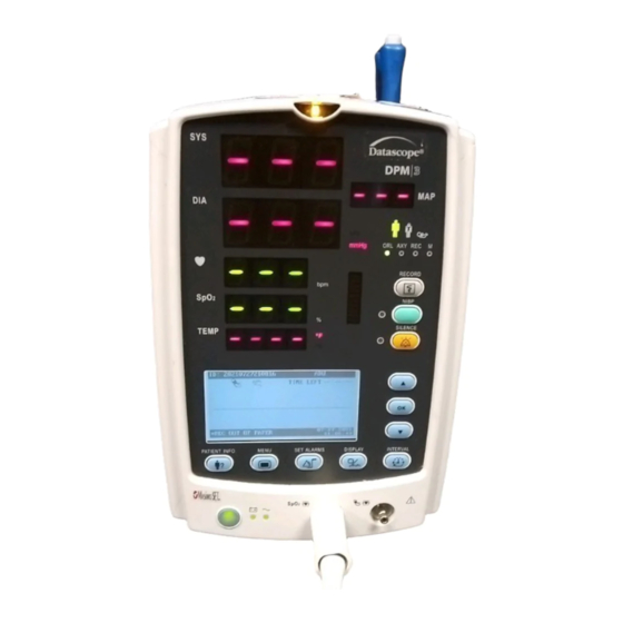
Page 21: Appearance
2.2 Appearance 2.2.1 Front Panel Figure 2-1 Front Panel... - Page 22 Alarm indicator The alarm indicator of this monitor is in compliance with the requirement of EN60825-1 A11 Class 1 for LED. The LED indicator varies its flash color and frequency to indicate different alarm levels. For details, refer to 5.2.1 Alarm Lamp. This LED displays the systolic pressure reading in the NIBP measurement.
- Page 23 12. Battery indicator It indicates the status of the battery. For details, refer to 2.4 Battery. 13. AC power indicator ON: It indicates that the AC power is applied to the monitor; OFF: It indicates that the monitor is not applied to the monitor. 14.
- Page 24 23. OK Press this key to select the highlighted option. In the trend view, pressing this key pops up the REVIEW SETUP menu. 24. Down Press this key to move the cursor down. 25. INTERVAL Press this key to switch between the INTERVAL menu and the Normal screen. 26.
-
Page 25: Rear Panel
2.2.2 Rear Panel Figure 2-2 Rear Panel TEMP probe sheath TEMP probe connector RS-232 connector:: used to connect the bar code scanner. Nurse call connector: used to connect the monitor to the hospital’s nurse call system. Network connector: used to connect the monitor to the CMS or PC. Equipotential grounding connector: connects the equipotential grounding connectors of other devices. -
Page 26: Recorder
2.2.3 Recorder The recorder is on the left side of the monitor. See the following figure. Power indicator Paper outlet Recorder door Figure 2-3 Recorder For details about the recorder, refer to 6 Recording... -
Page 27: Display
2.3 Display Figure 2-4 Display This monitor adopts the LCD display. It is able to display the following three parts: Patient information area This area displays patient ID, patient category and alarm status symbol. PLETH wave/NIBP timing area This area displays the PLETH wave and/or NIBP timing. Alarm information area On the left of this area is the technical alarm message or prompt message. -
Page 28: Battery
2.4 Battery Rechargeable batteries can be used to supply power to the monitor where AC mains is unavailable or whenever the power supply is interrupted. The battery is charged automatically when the monitor is connected to AC mains till it is full. If the power supply is lost during monitoring, the monitor can run on internal battery. -
Page 29: Battery Maintenance
2.4.1 Battery Maintenance 2.4.1.1 Conditioning a Battery A battery needs at least two conditioning cycles when it is used for the first time. A battery conditioning cycle is one uninterrupted charge of the battery, followed by an uninterrupted discharge of the battery. Batteries should be conditioned regularly to maintain their useful life. -
Page 30: Battery Recycling
NOTE Life expectancy of a battery depends on how frequent and how long it is used. For a properly maintained and stored lead-acid or lithium ion battery, its life expectancy is about 2 or 3 years respectively. For more aggressive use models, life expectancy can be less. -
Page 31: Installation And Maintenance
Installation and Maintenance 3.1 Installation WARNING The installation of the monitor must be carried out by personnel we authorize. The software copyright of the monitor is solely owned by our company. Any action to change, copy or exchange the software by any organization or person is regarded as copyright infringement and is not allowed. -
Page 32: Environmental Requirements
3.1.2 Environmental Requirements The operating environment of the monitor must meet the requirements specified in the section A.2 Environmental Specifications The environment where this monitor is to be used should be free from noise, vibration, dust, and corrosive or explosive and inflammable substances. For a cabinet mounted installation, allow sufficient room at the front and the rear of the cabinet for operation, maintenance and servicing. -
Page 33: Installation Method
3.1.5 Installation Method WARNING Equipments connected to this monitor must be certified according to the respective IEC standards (e.g. IEC 60950 for information technology equipment and IEC 60601-1 for medical electrical equipment). Furthermore all configurations shall comply with the valid version of IEC 60601-1-1. Any person who connects additional equipment to the signal input or signal output is responsible to ensure the system complies with the requirements of the valid version of IEC 60601-1-1. -
Page 34: Installing The Battery
3.1.5.2 Installing the battery The battery compartment is located at the bottom of the patient monitor. Follow the steps given below to install the battery. Push the compartment door in the marked direction to open the door. Flip the battery stopper to the left, as Figure 3-1 shows. Follow the marked polarity to insert the battery into the compartment, as Figure 3-2 shows. - Page 35 Figure 3-3 NOTE Be sure to charge the battery after a long-term storage or when you find the battery energy is low. A low-energy battery may not provide enough power to start the patient monitor. To charge the battery, connect the AC power to the monitor. The battery will be charged regardless the monitor is on or off.
- Page 36 3.1.5.5 Connecting the network cable The network connector of the monitor is a standard RJ45 connector. It connects the monitor with the specified central monitoring system, or with a PC for software upgrade and data export. To connect the monitor with CMS or PC, Connect one end of the network cable to the network connector of the monitor.
-
Page 37: Powering On The Monitor
3.1.6 Powering on the Monitor After installing the monitor, please power on it in the following procedure: Before using the monitor, please carry out corresponding safety inspection in accordance with Section 3.2.1Inspection. Press the Power Switch on the control panel. A beep will be heard. The system starts self-test and the start-up screen will be displayed. -
Page 38: Inspection
3.2.1 Inspection Make sure the qualified service personnel have implemented a complete inspection before putting the monitor into operation, after monitor servicing or system upgrading, or after the monitor has been used for 6-12 consecutive months. This is to ensure the normal operation of the system. - Page 39 The exterior surfaces of the equipment may be cleaned with a clean and soft cloth, sponge or cotton ball, dampened with a non-erosive cleaning solution. Drying off excess cleaning solution before cleaning the equipment is recommended. Following are examples of cleaning solutions: Diluted soap water Diluted ammonia water...
-
Page 40: Disinfection
3.2.3 Disinfection WARNING Disinfection may cause damage to the equipment; therefore, when preparing to disinfect the equipment, consult your hospital’s infection controllers or professionals. The cleaning solutions above can only be used for general cleaning. If you use them to control infections, we shall assume no responsibility for the effectiveness. -
Page 41: Menus And Screens
Menus and Screens 4.1 Patient Information The figure shows the PATIENT INFORMATION menu. Figure 4-1 In the PATIENT INFORMATION menu, you can set: PATIENT ID: The system automatically creates a patient ID each time the monitor is turned on. You can also: Input a patient ID by scanning the bar code: In the event BARCODE POWER is switched on, you can scan the bar code information using a bar code scanner. -
Page 42: System Setup
NOTE The system automatically creates a patient ID each time the monitor is turned Select appropriate patient type each time a patient is admitted. If you need to change patient type after the patient has been admitted, switch off QUICK ADMIT; press and then change PATIENT TYPE in the pop-up PATIENT INFORMATION menu. -
Page 43: Network Setup
Select SYSTEM SETUP→DEFAULT; and then select LOAD FACTORY CONFIG or LOAD USER CONFIG in the pop-up menu; Restart the monitor after turning it off for more than 120s; Change patient ID; Change patient type. KEY VOL 0 to 10 PULSE VOL 0 to 10 LCD BRIGHT 1 to 10... -
Page 44: Time Setup
4.2.3 Time Setup In the SYSTEM SETUP menu, select TIME SETUP. In the TIME SETUP menu, you can set the following items. DATE FORMAT: You can set DATE FORMAT to any of the following formats: YY-MM-DD MM-DD-YY DD-MM-YY System time: you can set the year, month, day, hour and minute respectively as required. -
Page 45: Nurse Call Setup
4.2.5 Nurse Call Setup Select SYSTEM SETUP→MAINTAIN→NURSE CALL. You can set the following items in the pop-up menu: SIGNAL DURATION CONTINUUM It indicates that the nurse call signal duration is the same with the alarm duration, namely, the nurse call signal lasts from the beginning of the alarm to the end of the alarm. -
Page 46: Version
WARNING Then nurse call settings shall not be changed by non-medical staff. 4.2.6 Version Select SYSTEM SETUP→MAINTAIN→VERSION, you can view information on the monitor’s hardware version and software version. 4.2.7 Configuration 4.2.7.1 Presetting Configuration If the monitor is turned off for less than 60 seconds, last configuration will be loaded automatically when it is restarted. -
Page 47: Exporting Data
4.2.7.3 Resuming Default Configuration In actual applications, the operator may change some settings. However, these changes may not always be appropriate or correct, particularly for a newly admitted patient. The monitor has the function of loading factory configuration so that you can resume the factory default configuration as desired. -
Page 48: Trend Screen
4.4 Trend Screen The Trend screen displays systolic pressure (S), diastolic pressure (D) and mean pressure (M), SpO , PR and TEMP, as shown in the figure below. Up to 1200 groups of data can be stored. The monitor stores trend data in either of the following modes: For SpO and TEMP values in monitor mode, the trend data is sampled value. -
Page 49: Standby State
4.5 Standby State 4.5.1 Entering the Standby State To enter the Standby state, press for less than 2 seconds and then select OK in the CONFIRM STANDBY STATE dialog box. 4.5.2 Exiting the Standby State In the Standby state, press any key on the front panel of the monitor. The EXIT STANDBY dialog box appears. - Page 50 FOR YOUR NOTES 4-10...
-
Page 51: Alarms
Alarms 5.1 Overview The monitor gives audible or visual alarms to indicate the medical staff when a vital sign of the patient appears abnormal, or mechanical or electrical problems occur to the monitor. WARNING A potential hazard can exist if different alarm presets are used for the same or similar equipment in any single area, e.g. -
Page 52: Alarm Levels
5.1.2 Alarm Levels By severity, the alarms of this monitor are divided into three priority levels: high level alarms, medium level alarms and low level alarms. High level alarms The patient is in danger and requires emergency treatment, or A serious technical problem occurs to the monitor, such as an error in the NIBP module self-test. -
Page 53: Alarm Lamp
5.2.1 Alarm Lamp When an alarm occurs, the alarm lamp on the front panel of the monitor flashes in different color and frequency to match the alarm levels as follows: High level alarms: the lamp quickly flashes red. Medium level alarms: the lamp slowly flashes yellow. -
Page 54: Alarm Status
5.3 Alarm Status Apart from the aforementioned alarm indicators, the patient monitor still uses symbols to indicate the alarm status: You can set alarms to the following status as desired: Audio off: is displayed at the right side of patient information area and a prompt message “AUDIO ALARM OFF”... -
Page 55: Physiological Alarm Off
WARNING If alarm tones are switched off, the monitor does not give audible alarm signal even if new alarms occur. So take care when you switch off alarm tones. 5.3.2 Physiological Alarm Off If alarms related to a parameter are switched off, the monitor does not generate alarms even if the measured parameter values exceed the alarm limit. -
Page 56: Alarm Silenced
In the alarm paused status, All alarm indications are disabled when a new physiological alarm occurs. Alarm lamp flashing and alarm tone are disabled and only alarm message is displayed when a new technical alarm occurs. The monitor automatically exits the alarm paused status when the alarm pause time expires. You can also press to manually leave the larm paused status. -
Page 57: Clearing Alarm Indications
5.4 Clearing Alarm Indications Clearing alarm light flashing and alarm tones For some technical alarms, the alarm lamp flashing and alarm tones are cleared and the alarm messages change to prompt messages during and after the alarm paused period if is pressed for less than 2 seconds. -
Page 58: Spo 2 Sensor Off Alarm
When any of the SpO or PR values exceeds the alarm limits, an alarm will be triggered. The ranges of SpO and PR limits are listed below: module Mindray DS SpO 0 to 100% 0 to 254 bpm Masimo SpO 0 to 100%... -
Page 59: Recording
Recording 6.1 Overview A thermal recorder can be installed on the left side panel of the monitor to print: Real-time PLETH waveform. Currently displayed trend data. All trend data of the current patient. 6.2 Using the Recorder 6.2.1 Printing Real-time PLETH waveform Press to enter the PLETH screen. -
Page 60: Loading Paper
6.3 Loading Paper Press the latch at the upper right of the recorder door to open the door. Lift the roller lever located at the upper left of the recorder as shown in the following figure. Install a new roll of paper into the compartment as shown below. The roller scrolls automatically to send the paper out of the compartment. -
Page 61: Removing Paper Jam
6.4 Removing Paper Jam If the recorder works improperly or produces unusual sound, check whether there is a paper jam. If yes, remove it following this procedure: Open the recorder door. Take out the jammed paper and tear off the draped part. Lift the lever on the upper left of the recorder. - Page 62 FOR YOUR NOTES...
-
Page 63: Spo 2 Monitoring
Monitoring This monitor can be equipped with any of the following SpO modules: Mindray DS SpO module Masimo SpO module Nellcor SpO module. A monitor, equipped with a Masimo or Nellcor SpO module, is marked by “Masimo SET” or “Nellcor” at the lower left corner of the front panel. The following pages respectively gives introduction to the above three SpO modules. -
Page 64: Safety
7.2 Safety WARNING Use only SpO sensors specified in this manual. Follow the SpO sensor’s instructions for use and adhere to all warnings and cautions. When a trend toward patient deoxygenation is indicated, blood samples should be analyzed by a co-oximeter to completely understand the patient’s condition. Do not use SpO sensors during magnetic resonance imaging (MRI). -
Page 65: Monitoring Procedure
NOTE Place the SpO sensor cable along the backside of patient’s hand. Make sure the fingernail is just opposite to the light emitted from the sensor. waveform amplitude is not proportional to the pulse strength. value is not proportional to the pulse rate. 7.3 Monitoring Procedure Power on the monitor. -
Page 66: Masimo Information
7.5 Masimo Information ® The MASIMO SET Product ® Masimo Patents This device is covered under one or more of the following U.S.A. patents: 5,758,644, 5,823,950, 6,011,986, 6,157,850, 6,263,222, 6,501,975, 7,469,157 and other applicable patents listed at www.masimo.com/patents.htm. No Implied License Possession or purchase of this device does not convey any express or implied license to use the device with unauthorized sensors or cables which would, alone, or in combination with this device, fall within the scope of one or more of the patents relating to this device. -
Page 67: Nibp Monitoring
NIBP Monitoring 8.1 Overview The Non-invasive Blood Pressure (NIBP) module measures blood pressure using the oscillometric method. This monitor can be applied to adult, pediatric, and neonatal patients. Three modes of measurement are available: Manual: Pressing starts an NIBP measurement manually. Auto: NIBP measurement is performed automatically at a preset interval. -
Page 68: Monitoring Procedure
8.2 Monitoring Procedure To perform NIBP measurement on a patient, follow the procedure below. Power on the monitor. Enter the PATIENT INFORMATION menu to select correct patient type. Plug the air hose in the NIBP connector of the monitor. Apply a cuff of proper size to the upper arm or the thigh of the patient. Connect the cuff with the air hose. -
Page 69: Operation Guides
Make sure that the cuff edge falls within the marked range. If it does not, use a larger or smaller cuff that will fit better. The limb chosen for taking the NIBP measurement should be placed at the same level as the patient's heart. -
Page 70: Measurement Limitations
To start a STAT NIBP measurement: Press to enter the INTERVAL menu and then select NIBP STAT to start a 5-minute continuous NIBP measurement. WARNING Continuous non-invasive blood pressure measurements may cause purpura, ischemia and neuropathy in the limb with the cuff. Inspect the application site regularly to ensure skin quality and inspect the extremity of the cuffed limb for normal color, warmth and sensitivity. -
Page 71: Nibp Reset, Calibration And Test For Air Leakage
8.4 NIBP Reset, Calibration and Test for Air Leakage 8.4.1 Resetting NIBP If the blood pressure pump works incorrectly but the monitor does not alarm for it, you can check the pump by resetting it. To reset the pump, select SYSTEM SETUP→MAINTAIN→ NIBP RESET. -
Page 72: Nibp Leakage Test
NOTE NIBP calibration shall be performed every two years or according to your hospital’s protocol. 8.4.3 NIBP Leakage Test You can test the pump for air leakage by selecting SYSTEM SETUP→MAINTAIN→NIBP LEAK TEST. With the NIBP cuff connected, you can test the air way for leakage by selecting NIBP LEAK TEST. -
Page 73: Temp Monitoring
TEMP Monitoring 9.1 Overview The SmarTemp™ TEMP module is intended for monitoring oral, axillary and rectal temperature of adult and pediatric patients and axillary temperature of neonatal patients. Be sure to set correct monitoring mode and position and to select appropriate temperature probe before taking measurement. -
Page 74: Temperature Setup
WARNING In MONITOR mode, the monitor stops measurement after performing measurement for five minutes later and the TEMP reading disappears. Long-time TEMP measurement may cause patient discomfort. 9.2 Temperature Setup In the SYSTEM SETUP menu, select TEMP SETUP, you can adjust: TEMP TYPE: PREDICT or MONITOR. -
Page 75: Oral Temperature Measurement
9.3.2 Oral Temperature Measurement Follow the procedure below to measure oral Temperature. Make sure that the oral/axillary probe is connected to the probe connector and the indication lamp beside the temperature unit lights to indicate that TEMP module properly operates. Select desired temperature type (the following procedure taking predict mode as an example) and set TEMP POSITION to ORAL. -
Page 76: Measuring Rectal Temperature
The monitor will give a beep as the temperature measurement is complete. The temperature reading is shown continuously. Withdraw the probe from the patient’s armpit when accurate temperature reading is obtained. Press firmly the ejection button on the top of the probe to eject the probe cover. -
Page 77: Temperature Measurement In Monitor Mode
9.3.5 Temperature Measurement in MONITOR Mode Temperature measurement can be taken in MONITOR mode. The monitor automatically enters the MONITOR mode in the following two cases: Accurate temperature is not reached in the PREDICT mode. Neither measurement is taken nor the probe is replaced in the probe sheath in 60s after the probe is withdrawn from the sheath. -
Page 78: Precautions
9.5 Precautions WARNING Check the probe before taking temperature measurement. The prompt information “TEMP NO PROBE” will be presented and an auditory alarm will be triggered if the TEMP probe is disconnected from the probe connector. Check the disposable probe cover for damage before using. Never use any probe cover for temperature measurement in case of damage or contamination. -
Page 79: Accessories
0010-30-42625 Sensor The SpO sensor material that patients or other staff will come into contact with has undertaken the bio-compatibility test and is verified to be in compliance with ISO 10993-1. For Mindray DS SpO Module Type Model Applicable Patient... - Page 80 Wavelengths emitted by 512F sensor intended for Mindray DS SpO module are red light 660 nm and infrared light 940 nm; wavelengths emitted by other sensors for Mindray DS module are red light 660 nm and infrared light 905 nm;...
-
Page 81: Nibp Accessories
10.2 NIBP Accessories Tubing Type Applicable Patient Adult, pediatric 509B-30-06259 Reusable Neonate 509B-30-06260 Cuff Limb Bladder Applicable Measurement Type Model Circumference Width Patient Site (cm) 10 to 19 0683-15-0001-01 Child Small Adult 18 to 26 12.2 0683-15-0002-01 Adult 25 to 35 15.1 0683-15-0003-01 Large adult... -
Page 82: Temp Accessories
10.3 TEMP Accessories Description Measurement Site oral/axillary 6006-30-39598 TEMP probe rectal 6006-30-39599 oral/axillary M09A-20-62062 Probe sheath rectal M09A-20-62062-51 Disposable probe cover (20 pcs) M09A-20-62124 Disposable probe cover (200 pcs) M09A-30-62126 Disposable probe cover (2000 pcs) M09A-30-62128 10.4 Others Description M05-010001-06 Lithium Ion Battery 0146-00-0099 Data Output Software Package... -
Page 83: A Product Specifications
Product Specifications A.1 Safety Specifications Item Specification Class I; internally/externally powered equipment Type of protection against When integrity of the external protection grounding or grounding electrical shock cable is doubtable, the equipment must be powered by the internal power (battery). Degree of protection /NIBP/TEMP: CF against electric shock... -
Page 84: Power Requirements
A.3 Power Requirements Item Specification AC mains Input voltage 100 to 240V Input current 0.7 to 0.3A Frequency 50/60Hz Battery Number of batteries Battery type Sealed lead-acid battery or lithium-ion battery Time to shutdown >5 min (after the first low-power alarm) Sealed lead-acid battery Nominal voltage 12VDC... -
Page 85: Hardware Specification
A.4 Hardware Specification Item Specification Size 177×240×170mm (width × height × depth)) Weight <3.5kg (battery included) Type Monochrome FSTN Size 80.3×41.0mm Resolution 320×160 pixels 7-segment LED Digit Displays Groups LED indicating lamp Groups Recorder Type Thermal dot array Horizontal resolution 160dots/cm 25 mm/s (paper speed: 25mm/s) Vertical resolution 80dots/cm... -
Page 86: Signal Output
IEC60601-1-8. A.6 SpO Specification A.6.1 Mindray DS SpO Specification All SpO sensors for Mindray DS SpO Module specified in the section 10.1meets the following specifications. Item Specification Measurement validation: The SpO2 accuracy has been validated in human studies against arterial blood sample reference measured with a CO-oximeter. -
Page 87: Masimo Spo Specification
Sensor type Totally neonates Data Arms 520N 122 (65 male & 57 female) 200 pairs 2.88% 518B 97 (51 male & 46 female) 200 pairs 2.38% This monitor with neonatal SpO2 sensors was also validated on adult subjects. Update period Averaging time Measurement range 20 to 254bpm... -
Page 88: Nellcor Spo Specification
A.6.3 Nellcor SpO Specification Item Specification Sensor Range Accuracy* 70% to 100% ±2% MAX-A, MAX-AL, MAX-N, MAX-P, MAX-I, MAX-FAST 0% to 69% Undefined 70 %to 100% ±2.5% OxiCliq A, OxiCliq N, OxiCliq measurement range P, OxiCliq I 0% to 69% Undefined and accuracy 70 %to 100%... -
Page 89: Temp Specification
Resolution 1mmHg Adult: 297±3 mmHg Over-pressure protection Pediatric: 240±3 mmHg Neonate: 147±3 mmHg Default initial pressure Neonate: 67±5 mmHg Measurement range 40 to 240bpm Resolution 1bpm ±3 bpm Accuracy A.8 TEMP Specification Item Specification Displayed parameter TEMP In MONITOR mode: 25 to 44 ºC (77 to 111.2 ºF) Measurement range In PREDICT mode: 35 to 43 ºC (95 to 109.4 ºF) Resolution... - Page 90 FOR YOUR NOTES...
- Page 91 The device meets the requirements of IEC60601-1-2. NOTE Use of accessories, transducers, and cables other than those specified may result in increased emission and/or decreased electromagnetic immunity of the patient monitoring equipment. The device or its components should not be used adjacent to or stacked with other equipment.
- Page 92 Guidance and Declaration - Electromagnetic Immunity The device is suitable for use in the electromagnetic environment specified below. The customer or the user of the device should assure that it is used in such an environment. Immunity tests Electromagnetic IEC60601 test level Compliance level environment - guidance Electrostatic...
- Page 93 Guidance and Declaration - Electromagnetic Immunity The device is suitable for use in the electromagnetic environment specified below. The customer or the user of the device should assure that it is used in such an environment. Electromagnetic environment — guidance Immunity IEC 60601 Compliance...
- Page 94 Recommended Separation Distances between Portable and Mobile RF, Communications Equipment and This Equipment The equipment is intended for use in an electromagnetic environment in which radiated RF disturbance are controlled. The customer or the user of the device can help prevent electromagnetic interference by maintaining a minimum distance between portable and mobile RF communications equipment (transmitters) and the device as recommended below, according to the maximum output power of the communication equipment.
-
Page 95: C Alarm Messages And Prompt Information
Alarm Messages and Prompt Information C.1 Physiological Alarm Messages Note: XX represents a parameter label, such as PR, SpO , NIBP, etc.The “L” field indicates the alarm level. H means high, M means medium and L means low. Alarm message Cause Action XX TOO HIGH... -
Page 96: General Alarm Messages Of Parameter Modules
C.2.1 General Alarm Messages of Parameter Modules Alarm message Cause Action XX INIT ERR N An error occurs to Restart the monitor. If the XX module the problem persists, during initialization. contact our service personnel for repair. Note: N stands for error code. XX COMM STOP Failure in communication... - Page 97 NIBP COMM ERR Yes Communication Restart the monitor. If between NIBP the problem still module and the host exists, contact our fails. service personnel for repair. LOOSE CUFF The NIBP cuff is not Check the patient’s properly connected. condition and verify patient type.
-
Page 98: Mindray Ds Spo Module Alarm Messages
C.2.3 Mindray DS SpO Module Alarm Messages Alarm message Cause Action SPO2 SENSOR The sensor is Make sure that the disconnected from sensor is placed at an the patient or the appropriate position monitor. and the monitor is connected to cables correctly. -
Page 99: Masimo Spo Module Alarm Messages
C.2.4 Masimo SpO Module Alarm Messages Alarm message Cause Action SPO2 SENSOR The sensor is Make sure that the disconnected from sensor is placed at an the patient or the appropriate position monitor. and the monitor is connected to cables correctly. - Page 100 SPO2 NO SENSOR The sensor is Disconnect and disconnected from reconnect the sensor the patient or the as directed by the monitor, or the instructions. If the sensor is not alarm remains, the properly connected. sensor or the cable might have been damaged.
-
Page 101: Nellcor Spo Module Alarm Messages
C.2.5 Nellcor SpO Module Alarm Messages Alarm message Cause Action SPO2 SENSOR The sensor is Make sure that the disconnected from sensor is placed at an the patient or the appropriate position monitor. and the monitor is connected to cables correctly. -
Page 102: Smartemp™ Temp Module Alarm Messages
C.2.6 SmarTemp™ TEMP Module Alarm Messages Alarm message Cause Action WARMUP TIMED TEMP probe initial Cool the TEMP temperature is too high. probe before taking measurement. WARMING The warming resistor in Replace the TEMP RESISTOR ERR the TEMP probe fails. probe. -
Page 103: Recorder Module Alarm Messages
Alarm message Cause Action TEMP WRONG A TEMP probe not Replace with a PROBE supplied by our TEMP probe we company is used. supply. TEMP COMM TEMP module is not Check if a TEMP available or TEMP module is module fails available. - Page 104 Alarm message Cause Action RECORDER The recorder has Place the recorder PAPER JAM recorded data on correctly and try paper for 30m long again. or more. RECORDER Error in recorder Clear recording tasks COMM ERR communication. and restart the monitor. If the TOO MANY REC Too many alarm problem remains,...
-
Page 105: System Alarm Messages
C.2.8 System Alarm Messages Alarm message Cause Action REAL CLOCK The system time is Reset the system time NEED SET incorrect. and then restart the monitor. REAL CLK NOT There is no button Install a button EXIST battery, or the battery or replace battery power is with a new one. -
Page 106: Prompt Messages
C.3 Prompt Messages Prompt message Cause Action SEARCH PULSE The SpO module is searching the Wait till the end of the search. pulse. SPO2 MOTION sensor is moving. Eliminate sensor movement. SPO2 Alarm Disabled alarm is switched off. Switch on SpO alarm. - Page 107 TEMP Prediction TEMP predictive measurement is Check TEMP reading. Over finished. TEMP Measure Over TEMP monitoring is over Remove the TEMP probe from patient and insert it in the probe sheath. OUTPUTTING... Data are being output. None CONNECTING... The monitor is connecting to the None PC software.
- Page 108 FOR YOUR NOTES C-14...
-
Page 109: D Factory Defaults
Factory Defaults This section lists the most important factory default settings. These settings are not user-adjustable. You can restore the factory default settings if necessary. Note: Column A indicates whether the item is affected by factory or user configuration. “√” represents that this item is affected by the configuration and user configuration will be loaded first when the monitor is restarted;... -
Page 110: System Setup
D.2 System Setup System Setup Factory Default Settings √ ALARM VOL √ KEY VOL √ PULSE VOL × LCD BRIGHT × LCD CONTRAST √ NIBP UNIT mmHg × TEMP TYPE PREDICT × TEMP POSITION ORAL √ ℃ TEMP UNIT × NET TYPE CMS+ ×... -
Page 111: Alarm Limit
D.3 Alarm Limit Mindray DS SpO Adult Pediatric Neonate √ √ √ PR HI √ PR LO Masimo SpO Adult Pediatric Neonate √ √ √ PR HI √ PR LO Nellcor SpO Adult Pediatric Neonate √ √ √ PR HI √... - Page 112 FOR YOUR NOTES...
-
Page 113: E Symbols And Abbreviation
Symbols and Abbreviation E.1 Units ampere ampere hour beats per minute ℃ centigrade centimeter decibel ℉ fahrenheit gram hour hertz inch inch kilo kilogram kilopascal litre pound meter milligrams minute milliliter millimeters mmHg millimeters of mercury millisecond millivolt milliwatt... -
Page 114: Symbols
nanometer second volt volt ampere Ω µA microampere µm micron µV microvolt watt E.2 Symbols minus percent divide ~ power plus equal to less than greater than less than or equal to greater than or equal to ± plus or minus ×... -
Page 115: Abbreviations
E.3 Abbreviations Association for Advancement of Medical AAMI Instrumentation alternating current adult ANSI American National Standard Institute Auxiliary output BTPS Body temperature and pressure Saturated channel CISPR International Special Committee on Radio Interference central monitoring system cmos Complementary Metal Oxide Semiconductor central processing unit direct current diastolic... - Page 116 magnetic resonance imaging not applied NIBP noninvasive blood pressure —— oxyCRG Oxygen Cardio-respirogram power photodetector PLETH plethysmogram pulse rate random access memory test NE2000 registers fail read-only memory arterial oxygen saturation from pulse oximetry systolic pressure TEMP temperature Video Graphic Array...
- Page 118 P/N: 046-000178-00 (3.0)
Need help?
Do you have a question about the dpm 3 and is the answer not in the manual?
Questions and answers