Table of Contents
Advertisement
Quick Links
Advertisement
Table of Contents

Related Manuals for Mindray DPM 4


Summary of Contents for Mindray DPM 4
- Page 1 DPM 4 Patient Monitor Operator’s Manual...
-
Page 3: Revision History
Contents of this manual are subject to change without prior notice. Revision number: 7.0 Release time: 2011-12 © Copyright 2008-2011 Mindray DS USA, Inc. All rights reserved. WARNING Federal Law (USA) restricts this device to sale by or on the order of a physician. - Page 4 Mindray DS USA, Inc. (hereinafter called Mindray DS) owns the intellectual property rights to this product and this manual. This manual may refer to information protected by copyrights or patents and does not convey any license under the copyright and patent rights of Mindray DS, nor the rights of others.
- Page 5 Manufacturer’s Responsibility All information contained in this manual is believed to be correct. Mindray DS shall not be liable for errors contained herein nor for incidental or consequential damages in connection with the furnishing or use of this manual. Mindray will not be liable for the effects on safety, reliability and performance of this product if: any installation operations, expansions, changes, modifications and repairs of this product are not conducted by Mindray DS authorized personnel;...
- Page 6 Return Policy In the event that it becomes necessary to return a unit to Mindray DS, follow the instructions below. Return authorization. Contact the Customer Service Department and obtain a Customer Service Authorization number. This number must appear on the outside of the shipping container. Returned shipments will not be accepted if the number is not clearly visible.
- Page 7 Preface Manual Purpose This manual contains the instructions necessary to operate the product safely and in accordance with its function and intended use. Observance of this manual is a prerequisite for proper product performance and correct operation and ensures patient and operator safety. This manual is based on the maximum configuration and therefore some contents may not apply to your product.
- Page 8 FOR YOUR NOTES...
-
Page 9: Table Of Contents
Contents 1 Safety..........................1-1 1.1 Safety Information ......................1-1 1.1.1 Dangers ......................1-2 1.1.2 Warnings......................1-2 1.1.3 Cautions ......................1-3 1.1.4 Notes ........................1-4 1.2 Equipment Symbols ......................1-5 2 The Basics ......................... 1-1 2.1 Monitor Description ......................2-1 2.1.1 Intended Use....................... 2-1 2.1.2 Contraindications .................... - Page 10 4.2.3 Modify Patient....................4-5 4.2.4 Clear Patient Data ....................4-5 4.2.5 Discharge Patient....................4-5 4.3 Configuration Setup ......................4-6 4.4 System Setup........................4-7 4.4.1 Face Select ......................4-8 4.4.2 Alarm Setup......................4-8 4.4.3 Time Setup ....................... 4-10 4.4.4 Recorder Setup ....................4-11 4.4.5 Data Output ......................
- Page 11 6.7 When an Alarm Occurs ....................6-8 7 Freezing Waveforms ......................7-1 7.1 Overview......................... 7-1 7.2 Freezing and Unfreezing ....................7-1 7.3 FROZEN Menu....................... 7-2 7.4 Waveform Recall......................7-3 7.5 Recording Frozen Waveforms..................7-3 8 Recording.......................... 8-1 8.1 Overview......................... 8-1 8.2 Recording Types......................
- Page 12 11.2 Mindray DS SpO Module ...................11-2 11.2.1 Principles of Operation..................11-2 11.2.2 Precautions ......................11-3 11.2.3 Monitoring Procedure..................11-4 11.2.4 Measurement Limitations................11-6 11.2.5 SpO Setup Menu ....................11-7 11.3 Masimo SpO Module....................11-9 11.3.1 Principles of Operation..................11-9 11.3.2 Precautions ....................11-11 11.3.3 Monitoring Procedure..................11-12 11.3.4 Measurement Limitations................11-12 11.3.5 SpO...
- Page 13 15.2.2 Preparations for CO Measurement..............15-3 15.2.3 CO Setup Menu .................... 15-5 15.2.4 CO User Maintain Menu................15-9 15.2.5 Maintenance and Cleaning ................15-11 15.3 Oridion CO Module ....................15-12 15.3.1 Principles of Operation................. 15-12 15.3.2 Preparations for CO Measurement.............. 15-13 15.3.3 CO Setup Menu ..................
- Page 14 FOR YOUR NOTES...
-
Page 15: Safety
Safety 1.1 Safety Information The safety statements presented in this chapter refer to the basic safety information that the operator of the patient monitor shall pay attention to and abide by. There are additional safety statements in other chapters or sections, which may be the same as or similar to the followings, or specific to the operations. -
Page 16: Dangers
1.1.1 Dangers There are no dangers that refer to the product in general. Specific “Danger” statements may be given in the respective sections of this operation manual. 1.1.2 Warnings WARNING The device is intended for use by qualified clinical physicians or well-trained nurses in the specified places. -
Page 17: Cautions
1.1.3 Cautions CAUTION To ensure patient safety, use only parts and accessories specified in this manual. Remove the battery from the patient monitor if it will not be used or not be connected to the power line for a long period. Disposable devices are intended for single use only. -
Page 18: Notes
1.1.4 Notes NOTE Keep this manual close to the patient monitor so that it can be obtained conveniently when necessary. This patient monitor complies with the requirements of CISPR11 (EN55011) class A. The software was developed per IEC601-1-4. The possibility of hazards arising from errors in software program is minimized. -
Page 19: Equipment Symbols
1.2 Equipment Symbols NOTE Some symbols may not appear on your equipment. Attention: Consult accompanying documents (this manual). Power ON/OFF Power ON/OFF Alternating current (AC) Battery indicator Type CF applied part. The unit displaying this symbol contains an F-type isolated (floating) patient part providing a high degree of protection against shock, and is suitable for use during defibrillation. - Page 20 ESD sensitivity Manufacture date Serial number European community representative This mark means that this device is fully in conformance with the Council Directive Concerning Medical Devices 93/42/EEC. The number adjacent to the CE marking (0123) is the number of the EU-notified body that certified meeting the requirements of Annex II of the Directive.
-
Page 21: The Basics
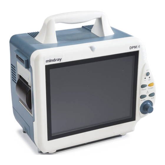
The Basics 2.1 Monitor Description This monitor integrates the functions of parameter measurement, waveform monitoring, freezing, and recording, etc. Its color TFT liquid crystal display is able to show patient parameters and waveforms clearly. The monitor also features compact size, lightweight, easy-to-carry handle and built-in battery, which make it portable, especially in hospital transport. -
Page 22: Functions
2.1.4 Functions This monitor is capable of monitoring the following parameters. Heart rate (HR) ECG waveform(s) ST segment analysis Arrhythmia analysis RESP Respiration rate (RR) Respiration waveform Pulse oxygen saturation (SpO Pulse rate (PR) plethysmogram NIBP Systolic pressure (NS), diastolic pressure (ND), mean pressure (NM) Pulse rate (PR) TEMP Temperature of channel 1 (T1), temperature of channel 2 (T2) -
Page 23: External Appearance
2.2 External Appearance 2.2.1 Front Panel Handle Alarm indicator Display Control panel Control knob Figure 2-1 Front Panel This monitor is designed to comply with the requirements of relative international safety standards (IEC60601-1, EN60601-2-27 and EN60601-2-30) for medical electrical equipment. This monitor has floating inputs and is protected against the effects of defibrillation and electrosurgery. -
Page 24: Left Side Panel
2.2.2 Left Side Panel Figure 2-2 Left Side Panel CF storage card connector Recorder Battery door... -
Page 25: Right Side Panel
2.2.3 Right Side Panel Figure 2-3 Right Side Panel (Oridion CO2) Figure 2-4 Right Side Panel (Mindray DS CO2) Temperature probe connector (channel 1) Temperature probe connector (channel 2) IBP1: IBP transducer connector (channel 1) IBP2: IBP transducer connector (channel 2) -
Page 26: Rear Panel
NOTE Some modules are optional. Their connectors may not be available on your patient monitor. 2.2.4 Rear Panel Figure 2-5 Rear Panel Fan Vent Speaker holes Mounting holes for support bracket. Network Connector: Standard RJ45 connector. Through network connector, this monitor can be connected with the central monitoring system, another monitor, or a PC. - Page 27 WARNING Accessory equipments connected to this patient monitor must be certified according to the respective IEC standards (e.g. IEC 60950 for information technology equipment and IEC 60601-1 for medical electrical equipment). Furthermore all configurations shall comply with the valid version of the system standard IEC 60601-1-1.
-
Page 28: Control Panel
2.3 Control Panel Figure 2-6 Control Panel Power switch This key turns the monitor ON and OFF. To turn OFF the monitor, please press this key and hold for more than 2 seconds. AC power indicator ON: AC power is applied to the monitor. OFF: AC power is not applied to the monitor. -
Page 29: Display
2.4 Display This monitor has a color TFT LCD display of high resolution. It is able to display patient parameters and waveforms clearly. The following is the standard interface when the monitor is operating normally. Figure 2-7 Main Screen 1.Patient information area It displays patient bed number and patient type. - Page 30 Physiological alarms area Physiological alarm messages are displayed in this area. In case of multiple messages, they will be displayed alternately. Waveforms area This area shows the waveforms of physiological parameters. The label of a waveform is displayed on the upper left. Parameter windows The parameter windows are located on the right of the waveform area, and are divided by white lines.
-
Page 31: Batteries
2.5 Batteries This monitor is designed to operate on battery (sealed lead-acid or Lithium Ion battery) power during intra-hospital patient transfer or whenever the power supply is interrupted. The battery is charged automatically when the monitor is connected to AC power, no matter the monitor is powered on or not. -
Page 32: Battery Guidelines
2.5.1 Battery Guidelines Life expectancy of a battery depends on how frequent and how long it is used. For a properly maintained and stored lead-acid or lithium ion battery, its life expectancy is about 2 or 3 years respectively. For more aggressive use models, life expectancy can be less. We recommend replacing lead acid batteries every 2 years and lithium ion batteries every 3 years. -
Page 33: Battery Maintenance
2.5.2 Battery Maintenance Conditioning a Battery A battery should be conditioned before it is used for the first time. A battery conditioning cycle is one uninterrupted charge of the battery, followed by an uninterrupted battery discharge and charge. . Batteries should be conditioned regularly to maintain their useful life. NOTE Condition a battery once when it is used or stored for 3 months, or when its operating time becomes noticeably shorter. -
Page 34: Battery Recycling
Checking a Battery The battery performance test must be performed every two years, before monitor repairs, or whenever the battery is suspected as being the source of the problems.The performance of a rechargeable battery may deteriorate over time. To check the performance of a battery, follow this procedure: Disconnect the monitor from the patient and stop all monitoring or measuring. -
Page 35: Wireless Network Card
2.6 Wireless Network Card This monitor can be configured with a wireless network card, which is connected to the CMS (Central Monitoring System) in the wireless mode and constructs with the CMS the monitoring network. Yon only need to insert the network cable into the network connector. The following figure shows the wireless network card correctly installed. - Page 36 The radio device used in the monitor is in compliance with the essential requirements and other relevant provisions of Directive 1999/5/EC(Radio Equipment and Telecommunications Terminal Equipment Directive). NOTE The wireless network card is connected to the patient monitor via 5V power supply and a network port in the monitor.
-
Page 37: Installation
Installation WARNING The installation of the monitor must be carried out by personnel authorized by us. The software copyright of the monitor is solely owned by our company. Any action to change, copy or exchange the software copyright by any organization or person is regarded as copyright infringement and is not allowed. -
Page 38: Environmental Requirements
WARNING Be sure to keep the packaging materials from children’s reach. Disposal of the packaging materials shall comply with your local requirements. The equipment might be contaminated in storage, transport or when used. Verify the package and the single use accessories are intact. In case of any damage, do not apply it to patients. -
Page 39: Installation Method
3.4 Installation Method 3.4.1 Bracket Mounting For details, please refer to the corresponding instructions for use of bracket mounting. 3.4.2 Connecting to AC Power Supply Use the original three-wire AC power cord. Connect the power cord to the receptacle for AC power cord on the rear panel of the monitor. -
Page 40: Connecting The Network Cable
3.4.6 Connecting the Network Cable The network connector of the monitor is a standard RJ45 connector. It connects the monitor with the central monitoring system, or with a PC for online upgrading or data output. It can also connect with another patient monitor for viewbed monitoring. Connect one end of the network cable with the network connector of the monitor. -
Page 41: Connecting To Vga Monitor
3.4.8 Connecting to VGA Monitor This monitor can be connected with a standard color VGA monitor. The VGA monitor will display the patient waveforms and parameters measured by the patient monitor. To connect the patient monitor with the VGA monitor, follow the steps as below. Power off the patient monitor. -
Page 42: Cf Storage Card
3.4.10 CF Storage Card Power off the monitor; Press down the lever (See Figure 1). Take out the model card (See Figure 2). Lever Plug the CF storage card (See Figure 3). The lever will then bounce out (See Figure 4). To unplug the CF storage card, follow the procedure below: Power off the monitor. -
Page 43: Powering On The Monitor
3.5 Powering on the Monitor After installing the monitor, please follow the procedures described below to power on the monitor: Before using the monitor, please carry out corresponding safety inspection as given in 16.1 Inspection. Press the Power Switch on the control panel. The alarm indicator will flash once in yellow and red. -
Page 44: Powering Off The Monitor
3.6 Powering off the Monitor To power off the monitor, please follow the procedures below: Confirm the patient monitoring is to be finished. Disconnect the cables and sensors between the monitor and the patient. Confirm whether to store or clear the patient monitoring data. Press the Power switch for more than 2 seconds, and the monitor will be powered off. -
Page 45: System Menu
System Menu 4.1 Overview This chapter only gives introduction to the system menu. Other menus will be described in the following chapters. Figure 4-1 System Menu Most menus displayed by the monitor share the same structure. As shown above, a menu is made up of four parts: Menu title: Summarizes the content of the current menu. -
Page 46: Patient Setup
4.2 Patient Setup Select PATIENT SETUP>> in SYSTEM MENU. The following menu appears. Figure 4-2 Patient Setup Menu This menu displays the patient’s information, as well as four buttons located below. If no patient is admitted, the buttons are: CLEAR PATIENT DATA QUICK ADMIT PATIENT ADMIT PATIENT MODIFY PATIENT... -
Page 47: Admit Patient
4.2.1 Admit Patient To admit a new patient, please follow this procedure: Select ADMIT PATIENT in PATIENT SETUP menu. Select YES in the pop-up CONFIRM TO CLEAR THE DATA menu. The menu as shown below appears. Figure 4-3 Patient Information Setup Enter the patient’s information details. - Page 48 NOTE If the PAT NO or NAME has not been input, “PATI. INFO. IMCMP” will be displayed in the patient information area. Select OK button, and the patient is admitted. If the monitor is connected with the central monitoring system, you can monitor the patient through the central monitoring system.
-
Page 49: Quick Admit Patient
4.2.2 Quick Admit Patient Select QUICK ADMIT PATIENT in PATIENT SETUP menu. Select YES in the pop-up CONFIRM TO CLEAR THE DATA menu. The following menu appears. You can set the PAT TYPE and status of PACE. Figure 4-4 Quick Admit Patient Select OK button, and the patient is admitted. -
Page 50: Configuration Setup
4.3 Configuration Setup Select CONFIG >> in the SYSTEM MENU. The following menu appears. Figure 4-5 Configuration menu If you have changed some settings during monitoring a patient and the changed settings are not proper, especially when a new patient is admitted, you can restore the factory configuration. According to the patient category, the monitor provides 3 kinds of factory configurations: factory adult configuration, factory pediatric configuration and factory neonatal configuration. -
Page 51: System Setup
4.4 System Setup Select SYSTEM SETUP>> in SYSTEM MENU. The following menu appears. Figure 4-6 System Setup SYSTEM SETUP menu contains the following submenus: FACE SELECT>> ALARM SETUP>> TIME SETUP>> RECORD>> DATA OUTPUT>> ANALOG>> MODULE SETUP>> TRACE SETUP>> MARK EVENT>>... -
Page 52: Face Select
4.4.1 Face Select Select FACE SELECT>> in SYSTEM SETUP menu. The following menu appears. Figure 4-7 Face Select In the FACE SELECT menu, options are available as shown above. For detailed information, see chapter Face Selection. 4.4.2 Alarm Setup Select ALARM SETUP>> in SYSTEM SETUP menu. The following menu appears. Figure 4-8 Alarm Setup... - Page 53 You can perform the following settings in the menu above: Alarm selection ALM SEL Options: COMMON ALM SETUP, XX ALM SETUP; (XX refers to physiological parameters such as HR, SPO2, etc.). If a parameter alarm setup is selected the corresponding alarm setup items will be displayed in the ALARM SETUP menu Alarm volume...
-
Page 54: Time Setup
4.4.3 Time Setup Select TIME SETUP>> in SYSTEM SETUP menu. The following menu appears. Figure 4-9 Time Setup With the control knob, you can change the year, month, day, hour, minute and second as well as select the displayed format of the time. YYYY, MM, and DD refer to year, month and day respectively. -
Page 55: Recorder Setup
4.4.4 Recorder Setup Select RECORD>> in SYSTEM SETUP menu. The following menu appears. Figure 4-10 Recorder Setup In this menu, you can adjust the following items: Select the first waveform to be recorded. The setting of this item REC WAVE1 should be different with those of REC WAVE 2 and REC WAVE3;... - Page 56 Real-time recording time RT REC TIME Options: CONTINUAL and 8s. Timing recording time TIMING REC TIME The interval between automatic recordings. Options: OFF, 10MIN, 20MIN, 30MIN, 40MIN, 50MIN, 1HOUR, 2HOURS, 3HOURS and 4HOURS. The monitor will start recording at the selected interval, record for 8s and stop automatically.
-
Page 57: Data Output
4.4.5 Data Output Select DATA OUTPUT>> in SYSTEM SETUP menu. The following menu appears. Figure 4-11 Data Output Output Procedure Disconnect all patient cables connected to the monitor. Verify the monitor is connected to the PC and the PC is running the Patient Information Recall System software. -
Page 58: Analog Output
4.4.6 Analog Output Select ANALOG >> in SYSTEM SETUP menu. The following menu appears. Figure 4-12 Analog Output You can perform the following settings in the menu above: Analog output ANALOG OUT Options: ON and OFF. When ON is selected, analog signals can be output from the auxiliary output port on the rear panel of the monitor. -
Page 59: Module Setup
4.4.7 Module Setup Select MODULE SETUP>> in SYSTEM SETUP menu. The following menu appears. Figure 4-13 Module Setup This menu allows you to enable or disable a parameter module to determine the information displayed on the main screen. As shown in the figure above, “√” indicates an enabled module. A module without the “√”... -
Page 60: Trace Setup
4.4.8 Trace Setup Select TRACE SETUP>> in SYSTEM SETUP menu. The following menu appears. Figure 4-14 Trace Setup This menu allows you to select the parameter waveform(s) to be displayed. The mark “√” indicates the parameter waveform will be displayed, and that without the mark will not be displayed. -
Page 61: Mark Event
4.4.9 Mark Event Select MARK EVENT>> in SYSTEM SETUP menu. The following menu appears. Figure 4-16 Mark Event This menu allows you to mark four different events, namely event A, B, C and D. The “@” symbol will appear in the frame of the event being selected. If you attempt to unmark an event, press the control knob again on the marked selection. -
Page 62: Selection Setup
4.5 Selection Setup Select SELECTION>> in SYSTEM MENU. The following menu appears. Figure 4-17 Selection Setup You can perform the following settings in this menu: Key volume KEY VOL The volume can be set between 0 and 10. 0 indicates the volume is off and 10 indicates the maximum volume. -
Page 63: Monitor Version
4.6 Monitor Version You can select VERSION>> in the SYSTEM MENU to check the version information as shown below.. However, the VERSION menu of you monitor may be different. Figure 4-18 Version You can see the monitor’s configuration by selecting DEVICE CONFIG LIST>> as shown below. However, the DEVICE CONFIG LIST menu of you monitor may be different. - Page 64 You can also see the device version by selecting DEVICE VERSION LIST>> as shown below. However, the DEVICE VERSION LIST menu of you monitor may be different. Figure 4-20 Device Version List 4-20...
-
Page 65: Maintenance
4.7 Maintenance Select MAINTAIN>> in SYSTEM MENU. The following menu appears. Figure 4-21 Enter Maintain Password Enter USER KEY, then select CONFIRM button. The following menu appears. Figure 4-22 User Maintain 4-21... - Page 66 You can perform the following settings: MONI NAME Monitor’s name. DEPT. The department where the monitor is located. BED NO The bed number where the monitor is located. Network type NET TYPE Options: CMS and CMS+. It indicates the bed number of a monitor in the monitoring LOCAL NET NO network.
- Page 67 LEAD NAMING Options: AHA and EURO; It indicates the configuration to be loaded when the monitor is POWERON CONFI powered on. The options are LAST CONF, USER ADU CONF, USER PED CONF and USER NEO CONF. LAST CONF is the real-time configuration that is selected before the monitor is last turn off.
-
Page 68: Alarm Setup
4.7.1 Alarm Setup Select ALARM SETUP>> to enter the following menu: Figure 4-23 Alarm Setup ENABLE: ALARM VOL can be set to 0. ALARM SOUND OFF DISABLE: ALARM VOL cannot be set to 0. MODE 1: the alarm sound interval of high level alarm is AUDIO OFF 8s and that of medium level alarm is 24s. -
Page 69: Ip Address Setup
4.7.2 IP Address Setup When the monitor is connected with the central monitoring system, and the NET TYPE is CMS+, you need to set the IP address of your monitor. Select IP ADDRESS SETUP in USER MAINTAIN menu. The following menu appears. For details, please contact with the technician responsible for the central monitoring system in your hospital. -
Page 70: Nurse Call Setup
4.7.4 Nurse Call Setup Select NURSE CALL SETUP >> in USER MAINTAIN menu. The following menu appears. Figure 4-26 Nurse Call Setup You can perform the following settings: SIGNAL DURATION Two options are available: PULSE, and CONTINUUM. PULSE When pulse is selected, a nurse call signal is a pulse signal lasting 1s. When multiple alarms occur simultaneously, only one pulse signal will be output. -
Page 71: Co User Maintain
Trigger Conditions A nurse call signal will be triggered only if all the following conditions are met: The nurse call function is enabled. An alarm of the preset alarm level and alarm type comes out. The monitor is not in the Alarms Paused or the System Silenced status. NOTE If no option in ALM LEV or ALM TYPE is selected, the nurse call signal will not be triggered in whatever condition. -
Page 72: Monitor Status
4.7.7 Monitor Status Select STATUS >> in ENTER MAINTAIN PASSWORD menu. The following menu appears. Figure 4-27 Monitor Status This menu can display a maximum of ten status messages. In UP-DOWN case of more than ten, you can select UP-DOWN to learn other status messages. -
Page 73: Demo Function
4.8 DEMO Function Select DEMO >> in SYSTEM MENU. The following menu appears. Figure 4-28 Input Demo Key The monitor enters the demonstration mode when the correct password is input in the menu above. The word DEMO will be displayed on the main screen. The purpose of the demonstration display is to demonstrate the performance of the monitor, and for training purposes. - Page 74 FORYOURNOTES 4-30...
-
Page 75: Face Selection
Face Selection 5.1 Standard Screen You can open the FACE SELECT menu by selecting FACE SELECT >> in SYSTEM SETUP menu. Figure 5-1 Face Select The standard screen is the default screen. If the current screen is not the standard screen, you may enter the standard screen by selecting STANDARD SCREEN and then selecting EXIT in FACE SELECT menu. -
Page 76: Trend Screen
5.2 Trend Screen To enter the following screen, select TREND SCREEN in FACE SELECT menu and then select EXIT. Figure 5-3 Trend Screen Trend graph Trend graphs locate to the right of the corresponding waveform in the waveform area, and display the trends of one parameter of each module. -
Page 77: Oxycrg Screen
5.3 OxyCRG Screen To enter the following screen, select oxyCRG SCREEN in FACE SELECT menu and then select EXIT. Figure 5-4 OxyCRG Screen Oxy CRG screen is located at the lower part of the waveform area, consisting of the HR trend, the SpO trend, and the RR (respiration rate) trend or the compressed respiration waveform. -
Page 78: Viewbed Screen
5.4 Viewbed Screen This monitor can view one parameter waveform and measured data from another patient monitor (viewbed monitor) on the same monitoring network. To enter the following screen, open FACE SELECT menu, select VIEWBED SCREEN, and then select EXIT. When connecting by wireless network (if your monitor has this feature), viewbed function is disabled. - Page 79 Viewbed monitor label The viewbed monitor lable allows you to select the viewbed monitor you want to view. It displays the bed number and patient name of the viewbed monitor. If they are not entered, the label displays blank. If the host monitor is not connected with any other monitor on the same network, the label displays N/A.
-
Page 80: Large Font Screen
5.5 Large Font Screen To enter the following screen, open FACE SELECT menu, select LARGE FONT SCREEN, and then select EXIT. Figure 5-6 Large Font Screen As shown above, the HR, SpO and NIBP values (diastolic pressure, mean pressure and systolic pressure) are displayed in large font. -
Page 81: Standby Mode
5.6 Standby Mode During patient transport or temporary departure of a patient, the monitor can be set to STANDBY mode. In this mode, the monitor suspends the monitoring and measurement on the patient and shields all alarm indications. Besides the WORK MODE of CO module (if available), which will also be changed to STANDBY, the previous menu settings and patient information keep unchanged. - Page 82 FOR YOUR NOTES...
-
Page 83: Alarms
Alarms 6.1 Overview The monitor gives audible or visual alarms to indicate the medical staff, when a vital sign of the patient appears abnormal, or mechanical or electrical problems occur to the monitor. Upon turning on the monitor, the alarm indicator will flash once in yellow and red. Then, a beep will be heard. -
Page 84: Alarm Levels
6.1.2 Alarm Levels The alarms are divided into three priority levels: high level alarms, medium level alarms and low level alarms. High level alarms The patient ‘s life is in danger and requires emergency treatment, or Serious technical problem occurs to the monitor, such as error in ECG module initialization. Medium level alarms Vital signs of the patient become abnormal, and patient requires immediate treatment, or Certain technical problem occurs to the monitor, such as error in temperature calibration. -
Page 85: Audible Alarms
6.2.2 Audible alarms The monitor uses different alarm tones to indicate different alarm levels. High level alarm: “DO-DO-DO--DO-DO---DO-DO-DO--DO-DO”. Medium level alarm: “DO-DO-DO”. Low level alarm: “DO”. Different intervals correspond to different alarm levels: High level alarm phonates once every 3 or 8 seconds. -
Page 86: Reminder Tones
6.2.5 Reminder Tones When system sounds are silenced or alarm tones are turned off, the patient monitor will give a single beep in case of an active alarm condition. You can set the REMINDER VOL to HIGH, MED or LOW. For details, please refer to 4.4.2. Alarm Setup The REMINDER TONE can be turned on or off , and you can set REMINDER INTERVAL as required. -
Page 87: Alarms Paused
6.3.2 Alarms Paused To pause all alarms of the monitor for 1, 2 or 3 minutes, press the SILENCE key on the control panel once (for less than 2 seconds). In Alarms Paused status, Visual alarms and audible alarms are both paused. The parameters generating physiological alarms and their upper or lower limits stop flashing. -
Page 88: Status Switchover
6.3.5 Status Switchover In the Normal status, Press the SILENCE key for less than 2 seconds to switch to the Alarms Paused status, or Press the SILENCE key for 2 seconds or more to switch to the System Silenced status. In the Alarms Paused status, Press the SILENCE key for less than 2 seconds to switch to the Normal status, or Press the SILENCE key for 2 seconds or more to switch to the System Silenced status. -
Page 89: Clearing Alarms
6.5 Clearing Alarms Generally the alarm indications of an alarm will automatically be cleared when the alarm condition that triggered the alarm ceases. However, you can also clear the alarm indications or the latched alarms by the following ways. Clearing audible and visual alarm indications For some technical alarms, the audible and visual alarm indications will be cleared if the monitor is set to the Alarms Paused status (by pressing the SILENCE key for less than 2 seconds), and the alarm message will be changed to prompt information during and after the alarms paused time. -
Page 90: Testing Alarms
6.6 Testing Alarms When the monitor starts up, a selftest will be performed automatically. The alarm indicator will flash once in yellow and red. Then, the system gives a beep indicating that the visible and audible alarm indicators are functioning correctly. The start-up screen is displayed. For further testing of individual measurement alarms, perform the measurement on yourself (for example SpO2 or CO2) or use a simulator. -
Page 91: Freezing Waveforms
Freezing Waveforms 7.1 Overview You can freeze the monitored waveforms of a patient as desired and view the waveforms of 40 seconds to gain a clear observation. Besides, the monitor can print three frozen waveforms using the recorder. The freezing function of the monitor has the following features. When the monitor enters the frozen mode, it exits all other menus automatically. -
Page 92: Frozen Menu
7.3 FROZEN Menu The FROZEN menu is displayed at the lower left corner. You can perform the following settings in this menu. Waveform 1 WAVE 1 It determines the first frozen waveform to be printed on the recorder paper. The options of waveform 1 include all waveforms displayed on the screen and OFF. -
Page 93: Waveform Recall
7.4 Waveform Recall In the frozen mode, select the RECALL option in the FROZEN menu, and the option name changes to L-RIGHT. Rotate the control knob clockwise, and the frozen waveforms move to the right. At the lower right corner of the first waveform is an arrow pointing upward. The time is indicated below the arrow. - Page 94 FOR YOUR NOTES...
-
Page 95: Recording
Recording 8.1 Overview A thermal recorder can be equipped with the monitor. The performance of the recorder is described as below. Records patient information and parameters. Records a maximum of three waveforms. The optional recording rates: 25mm/s and 50mm/s. The recording grid is optional. Multiple recording types are supported. - Page 96 Alarm recording Alarm recording is measured parameter recording. When a parameter alarm occurs, the recorder automatically records two waveforms of 8, 16 or 32 seconds (respectively 4, 8 or 16 seconds before and after the alarm. See 4.4.2 Alarm Setup) and some measured parameters.
-
Page 97: Recorder Operations
8.3 Recorder Operations Continuous real-time recording Press the RECORD key to start recording. Press the RECORD key again to stop the recording. 8-second real-time recording Press the RECORD key to start recording. The recording stops automatically in 8 seconds. Automatic recording The recorder starts recording automatically at the preset interval (RT REC TIME). - Page 98 NIBP measurement recording Select NIBP RECALL>> in SYSTEM MENU to open the NIBP RECALL window. Select the REC option to start recording. When the recording completes, the recorder stops automatically. Alarm event recording Select ALARM RECALL>> in SYSTEM MENU to open the ALARM RECALL window. Select the alarm recall time in the START and END fields.
-
Page 99: Installing Recorder Paper
8.4 Installing Recorder Paper Installing Procedure Press the latch at the upper right of the paper compartment door to releases the door. Lift the roller lever located at the upper left of the paper compartment as shown in the following figure. Insert a new roll of recorder paper into the compartment as shown below. - Page 100 For your notes...
-
Page 101: Recall
Recall 9.1 Overview The monitor is able to store important patient data so that the user can review and record the data as desired. Trend Graph Recall You can review the latest 1-hour trend graph of a measured parameter displayed every 1 or 5 seconds, or the latest 96-hour trend graph displayed every 1, 5 or 10 minutes. -
Page 102: Trend Graph Recall
9.2 Trend Graph Recall Select TREND GRAPH >> in SYSTEM MENU. The following window appears. Trend cursor 2. Cursor time Trend graph Y-axis X-axis Parameters area Figure 9-1 Trend Graph As shown above, PARA1, PARA2 and PARA3 allow you to select a parameter from the options. The trend graph of the selected parameter is displayed. - Page 103 When “OFF” is selected for “PARA1”, “PARA2” or “PARA3”, its trend graph will disappear, and then the trend graphs of other parameters will increase in amplitude and evenly occupy Parameters area. You can not select the same option for “PARA1”, “PARA2”...
-
Page 104: Trend Table Recall
9.3 Trend Table Recall Select TREND TABLE >> in SYSTEM MENU. The following window appears. Figure 9-2 Trend Table The TIME is displayed on the left of the trend table. On the top is the latest time. From the upper to the lower, the interval between two adjacent times depends on the preset resolution. - Page 105 UP-DOWN Rotate the control knob to highlight the UP-DOWN option, and press. If the mark is displayed at the lower right of the TIME field, you can rotate the control knob anticlockwise to page down and review the trend data of earlier time. If the mark is displayed at the upper right of the TIME field, you can rotate the control knob clockwise to page up and review the trend data of later time.
-
Page 106: Nibp Recall
9.4 NIBP Recall Select NIBP RECALL >> in SYSTEM MENU. The following window appears. Figure 9-3 NIBP Recall The NIBP RECALL window shows the non-invasive systolic pressure (NS), non-invasive mean pressure (NM), non-invasive diastolic pressure (ND), puse rate (PR) and the measurement time (TIME). -
Page 107: Alarm Event Recall
9.5 Alarm Event Recall Select ALARM RECALL >> in SYSTEM MENU. The following menu appears. Figure 9-4 Alarm Recall Condition Selections In this menu, you may select the conditions of alarm review: ALARM RECALL TIME You can select the desired start time and end time for review. The end time can be set to either CURRENT TIME or SELF-DEFINE. - Page 108 Two waveforms at the time of the alarm event. You can set the waveform length by selecting from the ALM REC TIME options in the ALARM SETUP menu. Please refer to 4.4.2Alarm Setup. . Figure 9-5 Alarm Event Recall UP-DOWN The monitor is able to store a maximum of 70 alarm events.
-
Page 109: Non-Volatile Data Storage
9.6 Non-Volatile Data Storage To avoid losing patient’s data when the monitor is powered off intentionally or accidentally, the monitor can be equipped with a CF storage card (optional) to realize the non-volatile data storage function. During monitoring, the patient’s data, including trend data, NIBP measurement results, alarm events, arrhythmia events, and relative waveforms, will be saved into the CF storage card. - Page 110 FORYOURNOTES 9-10...
-
Page 111: Ecg/Resp Monitoring
ECG/RESP Monitoring 10.1 Overview Two algorithm packages are optional for ECG monitoring: Mindray DS algorithm package This package provides 3/5-lead monitoring. Mortara algorithm package This package provides 3/5-lead monitoring, ST-segment analysis and extended ARR analysis. 10.2 ECG Monitoring Procedure 10.2.1 Preparation... -
Page 112: Electrode Placement
10.2.2 Electrode Placement WARNING Use only the specified ECG cable for monitoring. When applying electrodes or connecting cables, make sure they are not connected to any conductive part or the ground. Verify that all ECG electrodes, including neutral electrodes, are securely attached to the patient. Skin irritation may result from the continuous application of the ECG electrodes. - Page 113 3-Leadwire Electrode Placement Following is the configuration per European standard when using three leadwires: R (right arm) electrode: near the right shoulder, directly below the clavicle. L (left arm) electrode: near the left shoulder, directly below the clavicle. F (left leg) electrode: on the left hypogastrium. Figure 10-1 Positions of 3-Leadwire Electrode Placement The chart below shows the label used to identify each leadwire.
- Page 114 5-Leadwire Electrode Placement Following is the configuration per American standard when using five leadwires: Figure 10-2 5-Leadwire Electrode Placement RA (right arm) electrode: near the right shoulder, directly below the clavicle. LA (left arm) electrode: near the left shoulder, directly below the clavicle. RL (right leg) electrode: on the right hypogastrium.
- Page 115 When attaching the chest electrode to the back of a patient, place it at one the following sites: V7: On the 5th intercostal space at the left posterior axillary line of the back. V7R: On the 5th intercostal space at the right posterior axillary line of the back. Figure 10-3 Positions of Chest Electrode The chart below shows the label used to identify each leadwire.
-
Page 116: Characteristics Of Quality Ecg Signal
WARNING When using Electrosurgery equipment, patient leads should be placed in a position that is equal distance from the Electrosurgery electrotome and the grounding plate to avoid burns to the patient. The Electrosurgery equipment wire and the ECG cable must be kept separated and not allowed to tangle. When using Electrosurgery equipment, never place the ECG electrodes near the grounding plate of the Electrosurgery device. -
Page 117: Ecg Display
10.3 ECG Display 10.3.1 ECG Waveform In the standard screen, one or two ECG waveform(s) is (are) displayed at the top of the display when LEAD TYPE is set to 3 LEADS or 5LEADS respectively in the ECG SETUP menu. Figure 10-5 ECG Waveforms As shown above, when 5 LEADS is selected, five labels are located above the ECG waveforms: ECG lead of channel 1 (Primary lead) -
Page 118: Ecg Parameters
WARNING Only in the DIAGNOSTIC mode will the monitor provide non-processed real signal waveforms. In the MONITOR or SURGERY mode, the ECG waveforms may have slight distortions and the result of the ST segment analysis may be affected greatly. In the SURGERY mode, the ARR analysis result may be affected to some extent. -
Page 119: Ecg Setup Menu
To display the ECG SETUP menu, use the knob to select the ECG label in the parameter windows. The options available in the menu vary with each algorithm package Figure 10-7 ECG SETUP Menu (Mindray DS Algorithm Package) Figure 10-8 ECG SETUP Menu (Mortara Algorithm Package) - Page 120 The options of ECG SETUP menu are listed below. However, your algorithm package may not include some of these options. HR ALM Heart rate alarm on/off status ON: When a heart rate alarm occurs, the monitor gives alarm indications and stores the alarm; OFF: When a heart rate alarm occurs, the monitor neither gives alarm indications nor stores the alarm;...
- Page 121 AUTO: The monitor automatically selects an optimal channel to calculate the heart rate. This option is available in Mindray DS algorithm package only. For Mortara algorithm package, the monitor uses both channels to calculate the heart rate simultaneously. LEAD TYPE Options: 3 LEADS, 5 LEADS;...
- Page 122 Figure 10-9 Other ECG Setup (Mindray DS Algorithm Package) Figure 10-10 Other ECG Setup (Mortara Algorithm Package) In this menu, you can select any of the displayed option. All options are listed below. Your algorithm package may not include some of these options.
- Page 123 Switching rules for SMART LEAD OFF: LEAD OFF condition HR-derived channel automatically switches to RA OFF LL OFF LA OFF V OFF RL OFF None Any two out of LL, RA and LA fall off. None LL, RA or LA, and V fall off together Same as LL, RA or LA falls off.
- Page 124 PACER RATE Some pace pulses may be difficult to suppress. When this happens, the pace pulse may be counted as a QRS complex, and could result in incorrect HR measurements and failure to detect some arrhythmias. This option allows you to input the heart rate of pacemaker, so that the software can calculate the HR and detect the arrhythmias more accurately.
- Page 125 WARNING Improper defibrillation will endanger the patient’s safety. You user should decide whether to defibrillate the patient based on the patient’s actual condition. Before defibrillating the patient, the user should ensure the defibrillator and the monitor have been tested as a system and the two devices can work together safely and effectively.
-
Page 126: St Analysis
10.5 ST Analysis 10.5.1 Overview The function of ST analysis is optional. In the factory configuration, ST analysis is disabled. When turning ST ANALYSIS on, the monitor selects DIAGNOSTIC mode automatically. You can set the monitor to MONITOR or SURGERY mode as required. However, ST analysis will turn off automatically. - Page 127 NOTE ST analysis can be carried out only when the filter method is set to DIAGNOSTIC. When ST analysis is switched on, the filter method will automatically switch to DIAGNOSTIC if it is not in the diagnostic mode. However, if you switch the filter method to MONITOR or SURGERY, ST analysis will turn off automatically.
-
Page 128: Adjusting St Measurement Point
10.5.3 Adjusting ST Measurement Point The ST measurement for each beat complex is the ventical difference between two measurement points. The isoelectric point provides the baseline for the measurement and the ST point provides the other measurement point. R wave T wave P wave ST measurement value... - Page 129 Mortara algorithm package To adjust the points: Select DEF POINT >> in the ST ANALYSIS menu to open the following window. Three vertical cursors indicate the positions of the ISO, J and ST points. Figure 10-14 ST Measurement Point Select VIEW LEADS option, and then rotate the knob to select a suitable ECG lead for ST measurement, with a visible J-point and a visible P wave.
-
Page 130: Arrhythmia Analysis
10.6 Arrhythmia Analysis 10.6.1 Overview The monitor uses the user-selected primary or secondary ECG lead for arrhythmia analysis. In clinical application, the medical professionals can use the arrhythmia analysis to evaluate patients’ condition (such as heart rate, PVCs rate, rhythm and ectopic beat) and give proper treatment. -
Page 131: Arrhythimia Options
10.6.2 Arrhythimia Options Mortara algorithm package When Mortara algorithm package is configured, your monitor has the following extended arrhythmia analysis option. Arrhythmia Message Description ASYSTOLE No QRS complex within the defined time in absence of ventricular fibrillation or chaotic signals. VFIB Ventricular fibrillation occurs and persists for 6 seconds. -
Page 132: Arrhythmia Analysis Menu
10.6.3 Arrhythmia Analysis Menu Select ARR ANALYSIS >> in ECG SETUP menu. The following menu appears. The menu items vary with the algorithm packages. Figure 10-15 Arrhythmia Analysis (Mortara algorithm package) In this menu, you can perform the following settings: ARR ANAL Arrhythmia analysis ON: Enables the arrhythmia analysis;... -
Page 133: Arrhythimia Relearn
10.6.4 Arrhythimia Relearn During ECG monitoring, you may need to start an arrhythmia relearn when a dramatic change in the patient’s ECG pattern has occurred. A change in the ECG pattern could result in: Incorrect arrhythmia alarms, Loss of ST measurements, and/or Inaccurate heart rate. - Page 134 Figure 10-16 Arrhythmia Alarm Setup (Mortara algorithm package) In the menu, the ALM field indicates the alarm on/off status, REC indicates the alarm recording on/off status and LEV indicates the alarm level. You can change the settings as described below. ALL ALM ON All alarms on Enables all arrhythmia alarms;...
-
Page 135: Arr Threshold
10.6.6 Arr Threshold Select ARR THRESHOLD >> in the ECG SETUP menu and the following menu appears. You can change the threshold settings in this menu. An alarm will be triggered when a rate exceeds a threshold. Figure 10-17 ARR Threshold Setup ARR Event Range Default... -
Page 136: Arrhythmia Recall
10.6.7 Arrhythmia Recall Select ARR RECALL >> in the ARR ANALYSIS menu. The following menu appears. You can review any stored arrhythmia event in this menu. Figure 10-18 Arrhythmia Recall You can perform the following operations: UP-DOWN A maximum of 10 arrhythmia events can be displayed in the window each time. - Page 137 Figure 10-19 Arrhythmia waveform Review You can perform the following operations: UP-DOWN This option allows you to page up and down to review the waveform and the parameters of other arrhythmia events. L-RIGHT This option allows you to review 8-second waveform of the currently displayed arrhythmia event.
-
Page 138: Resp Monitoring
10.7 RESP Monitoring 10.7.1 Overview Respiration is detected by measuring thoracic impedance. The monitor measures the change of the impedanec between the RA and LA electrodes of the ECG lead I, or the RA and LL electrodes of the ECG lead II, and produces a respiration waveform as shown below. Figure 10-20 Respiration Waveform and Parameter Waveform name. -
Page 139: Electrode Placement
10.7.2 Electrode Placement Since the same electrodes are used for ECG and respiration monitoring, the electrode placement is very important. Some patients, due to their clinical condition, expand their chest laterally, causing a negative intrathoracic pressure. In these cases it is better to place the two electrodes used for respiration monitoring laterally in the right axillary and left lateral chest areas, at the maximum point of the breathing movement, to optimize the respiratory waveform. -
Page 140: Respiration Setup
10.7.3 Respiration Setup Selecting the RESP label on the screen opens the following menu. Figure 10-22 RESP Setup Menu In this menu, you can perform the following settings. Alarm on/off ON: When a respiration rate alarm occurs, the monitor gives alarm indications and stores the alarm;... - Page 141 For different patient types, the upper/lower limits of the respiration rate alarm may vary in the following range. Patient type Upper Limit Lower Limit Increment (breath/min) Adult (lower limit+2) ~120 0~(upper limit-2) Neonate/pediatric (lower limit+2) ~150 0~(upper limit-2) APNEA ALM Apnea alarm Determines whether the patient’s cessation of breath is an apnea event.
-
Page 142: Maintenance And Cleaning
10.8 Maintenance and Cleaning WARNING Before cleaning the ECG cable, be sure to disconnect the monitor from the ECG cable, or shut down the system and disconnect all power cords from the outlet. If the ECG cable is damaged or aged, replace with a new one. Cleaning The exterior surfaces of the ECG cable may be cleaned with a soft cloth, dampened with the alcohol, and then be air-dried or dried with a clean dry cloth. -
Page 143: Spo Monitoring
Monitoring 11.1 Overview The monitor measures the patients’ SpO (oxygen saturation) and displays: Pulse rate (PR) value in the ECG or SpO2 parameter window. PLETH waveform in the waveforms area. Oxygen saturation (SpO2%) value in the SpO2 parameter window. The PR value is displayed in the ECG parameter window only if: SpO2 is selected from the HR FROM options in the ECG SETUP menu;... -
Page 144: Mindray Ds Spo
SpO2 and SPO2 are used interchangeably in this chapter. 11.2 Mindray DS SpO Module NOTE This section is only applicable to the monitor equipped with a Mindray DS SpO2 module. 11.2.1 Principles of Operation monitoring is a non-invasive technique used to measure the amount of oxygenated hemoglobin and pulse rate by measuring the absorption of selected wavelengths of light. -
Page 145: Precautions
11.2.2 Precautions WARNING The SpO2 value might be overestimated in the presence of Hb-CO, Met-Hb or dye dilution chemicals. Check if the sensor cable is in normal condition before monitoring. Do not use the SpO2 sensor once the package or the sensor is found damaged. Verify sensor cable fault detection before beginning monitoring. -
Page 146: Monitoring Procedure
11.2.3 Monitoring Procedure Sensor selection for SpO measurement depends on the patient type. For an adult patient, you can choose a finger SpO sensor; for an infant patient, you can choose a hand or toe sensor. Refer to the following procedure. Power on the monitor. - Page 147 Figure 11-4 Neonate Sensor Placement (2) Wind the SpO sensor around a hand or foot of a neonate patient. Hold the sensor, pull the belt and fit one of its sides with “V” edge into the “V” groove on the corresponding side of the sheath. Appropriately elongate the belt to about 20mm, and fit the “V”...
-
Page 148: Measurement Limitations
11.2.4 Measurement Limitations If the accuracy of any measurement does not seem reasonable, first check the patient’s vital signs by an alternate method. Then check the instrument for proper function. Inaccurate measurements may be caused by: Improper SpO2 sensor; High-frequency electrical noise, including noise created by the host system, or noise from external sources, such as electrosurgical apparatus connected to the system;... -
Page 149: Spo 2 Setup Menu
11.2.5 SpO Setup Menu Selecting the SPO label in the parameter window opens the following menu. Figure 11-6 SpO2 Setup Menu You can perform the following settings in this menu. SpO2 alarm on/off status ON: When a SpO2 alarm occurs, the monitor gives alarm indications and stores the alarm;... - Page 150 and PR alarm limits: Parameter Upper Limit Lower Limit Step SpO2 (lower limit+1) ~100 0~(upper limit-1) (lower limit+2) ~254 0~(upper limit-2) The SpO and PR alarm limits in factory configuration: Parameter Patient type Upper limit Lower limit Adult SpO2 Pediatric Neonate Adult Pediatric...
-
Page 151: Masimo Spo Module
CONFIG >> You can select this option to access the SPO2 CONFIG menu, in which you may select FACTORY CONFIG or USER CONFIG. After finishing your selection and exiting the menu, the system pops up a dialog box asking for your confirmation. - Page 152 Again, R is the ratio of two arterial pulse-added absorbance signals and its value is used to find the saturation SpO in an empirically derived equation into the software. The values in the empirically derived equation are based upon human blood studies against a laboratory co-oximeter on healthy adult volunteers in induced hypoxia studies.
-
Page 153: Precautions
11.3.2 Precautions WARNING The pulse wave from the MS-7 module must NOT be used for apnea monitoring. As a trend towards patient deoxygenation is indicated, blood samples should be analyzed by a laboratory co-oximeter to completely understand the patient’s condition. If an alarm condition (other than exceptions listed herein) occurs in the Alarm Sound Off status, the monitor only gives visual alarm symbols. -
Page 154: Monitoring Procedure
11.3.3 Monitoring Procedure Follow the procedure as below: Power on the monitor. Attach the sensor to the proper site on the patient. Plug the connector of the sensor extension cable into the SpO2 connector on monitor. The process of SpO plethysmogram measurement is generally the same. -
Page 155: Spo Setup Menu
11.3.5 SpO Setup Menu Selecting the SPO label in the parameter window opens the following menu. Figure 11-7 MASIMO SpO2 Setup Menu You can perform the following settings in this menu. SpO2 alarm on/off status ON: When a SpO2 alarm occurs, the monitor gives alarm indications and stores the alarm;... - Page 156 and PR alarm limits: Parameter Upper Limit Lower Limit Step SpO2 (lower limit+1) ~100 0~(upper limit-1) (lower limit+2) ~254 0~(upper limit-2) The SpO and PR alarm limits in factory configuration: Parameter Patient type Upper limit Lower limit Adult SpO2 Pediatric Neonate Adult Pediatric...
-
Page 157: Sensors And Accessories
11.3.6 Sensors and Accessories If your monitor is equipped with a Masimo SpO module, use only Masimo oximetry sensors for measurements. Other sensors may cause improper pulse oximeter performance. Before use, carefully read the directions for the sensor. Tissue damage can be caused by incorrect application or use of a sensor. -
Page 158: Masimo Information
Cleaning and Reusing a Masimo Sensor Reusable sensors can be cleaned per the following procedure: Remove the sensor from the patient. Disconnect the sensor from the monitor. Wipe the entire sensor with a 70% isopropyl alcohol pad, and clean with a dry cloth. Allow the sensor to air-dry before returning it to operation. -
Page 159: Nellcor Spo
11.4 Nellcor SpO Module NOTE This section is only applicable to the monitor equipped with a Nellcor SpO2 module. 11.4.1 Principles of Operation Bone, tissue, pigmentation, and venous vessels normally absorb a constant amount of light over time. The arteriolar bed normally pulsates and absorbs variable amounts of light during the pulsations. - Page 160 Automatic Calibration Because light absorption by hemoglobin is wavelength dependent and because the mean wavelength of LEDs varies, a monitor must know the mean wavelength of the sensor’s red LED to accurately measure SpO . During manufacturing, the mean wavelength of the red LED is encoded in a resistor in the sensor.
-
Page 161: Precautions
11.4.2 Precautions WARNING Pulse oximeter can overestimate the SpO2 value in the presence of Hb-CO, Met-Hb or dye dilution chemicals. ES (Electrosurgery) equipment wire and SpO2 cable must not be tangled up. Carefully route patient cabling to reduce the possibility of patient entanglement or strangulation. -
Page 162: Measurement Limitations
11.4.4 Measurement Limitations If the accuracy of any measurement does not seem reasonable, first check the patient’s vital signs by an alternate method. Then check the instrument for proper function. Inaccurate measurements may be caused by: Incorrect sensor application or use; Placement of a sensor on the same extremity with a blood pressure cuff, arterial catheter, or intravascular line;... -
Page 163: Spo Setup Menu
11.4.5 SpO Setup Menu Selecting the SPO label in the parameter window opens the following menu. Figure 11-9 SpO2 Setup Menu You can perform the following settings in this menu. SpO2 alarm on/off status ON: When a SpO2 alarm occurs, the monitor gives alarm indications and stores the alarm;... - Page 164 and PR alarm limits: Parameter Upper Limit Lower Limit Step SpO2 (lower limit+1) ~100 0~(upper limit-1) (lower limit+2) ~254 0~(upper limit-2) The SpO and PR alarm limits in factory configuration: Parameter Patient type Upper limit Lower limit Adult SpO2 Pediatric Neonate Adult Pediatric...
-
Page 165: Accessories
11.4.6 Accessories If your monitor is equipped with a Nellcor SpO module, use only Nellcor oximetry sensors for measurements. Other sensors may cause improper pulse oximeter performance. Before use, carefully read the directions for the sensor. When selecting a sensor, consider, the patient’s weight and motion, the adequacy of perfusion, the available sensor sites, and the required disinfection. - Page 166 FOR YOUR NOTES 11-24...
-
Page 167: Nibp Monitoring
NIBP Monitoring 12.1 Overview The Non-invasive Blood Pressure (NIBP) module measures blood pressure using the oscillometric method. This monitor can be applied to adult, pediatric, and neonatal patients. Three modes of measurement are available: manual, automatic and continuous. Manual: Pressing the NIBP key on the control panel starts a NIBP measurement. Auto: The NIBP measurement is conducted automatically at a preset interval. -
Page 168: Monitoring Procedure
12.2 Monitoring Procedure WARNING You must not perform NIBP measurements on patients with sickle-cell disease or under any condition in which the skin is damaged or expected to be damaged. For a thrombasthemia patient, it is important to determine whether measurement of the blood pressure shall be done automatically. -
Page 169: Cuff Selection And Placement
12.2.1 Cuff Selection and Placement Identify the patient limb circumference. Select appropriate cuff; limb circumference is identified on each cuff. Verify the cuff is completely deflated; place cuff around extremity being used and make sure the marking φ matches artery location. Verify the cuff is not wrapped too tightly around the limb. -
Page 170: Operation Guides
12.2.2 Operation Guides To start a manual NIBP measurement Access the NIBP SETUP menu and select MANUAL from the INTERVAL option; then, press the NIBP key on the control panel to start a manual NIBP measurement; or During the interval between two auto NIBP measurements, press the NIBP key on the control panel to start a manual NIBP measurement. -
Page 171: Measurement Limitations
12.3 Measurement Limitations Non-invasive blood pressure measurement uses the oscillometric method of measurement. The monitor detects the regular arterial pressure pulse. In some circumstances when the patient's condition makes it difficult to detect this pulse, the measurement becomes unreliable and the measurement time increases. -
Page 172: Nibp Setup Menu
12.4 NIBP Setup Menu Selecting the NIBP label in the parameter area opens the following menu. Figure 12-2 NIBP Setup Menu You can perform the following settings in this menu. NIBP alarm on/off status ON: When a NIBP alarm occurs, the monitor gives alarm indications and stores the alarm;... - Page 173 SYS ALM HI Determines the upper limit of the systolic pressure. SYS ALM LO Determines the lower limit of the systolic pressure. MEAN ALM HI Determines the upper limit of the mean pressure. MEAN ALM LO Determines the lower limit of the mean pressure. DIA ALM HI Determines the upper limit of the diastolic pressure.
- Page 174 DISPLAY WAY 1 GROUP: The NIBP parameter area only displays a group of NIBP values obtained in the latest measurement. GROUPS: Multiple groups of measurement values are displayed at the lower left corner of the screen as shown below. DATE TIME 2006-6-12 16:06:00...
-
Page 175: Calibration
12.4.1 Calibration If you select the CALIBRATE option, the monitor starts the NIBP calibration and the CALIBRATE option changes to STOP CAL. Selecting the option again stops the calibration. Calibrate the cuff pressure reading with a calibrated reference manometer (or mercury manometer) with accuracy higher than 1mmHg. -
Page 176: Testing For Air Leakage
12.4.2 Testing for Air Leakage The PNEUMATIC option is used to test air leakage. When the NIBP cuff is connected, select this option to start the NIBP inflation and test whether the air leakage occurs in the airway. If the test is passed, no prompt information will be displayed;... -
Page 177: Maintenance And Cleaning
12.5 Maintenance and Cleaning WARNING Do not press the rubber tube on the cuff with excessive strength. When a reusable cuff is not connected to the monitor or is being cleaned, always cover the rubber tube with a lid. Avoid splashing liquid into the rubber tube or the monitor inadvertently. - Page 178 CAUTION Some disinfectants may cause skin irritation. Please rinse cuff thoroughly with water to remove any residual disinfectants. Using dark colored disinfectants may stain the cuffs. Test a single cuff to ensure that no damage will occur. Disposable Blood Pressure Cuffs Disposable cuffs are intended for single patient use only.
-
Page 179: Temp Monitoring
TEMP Monitoring 13.1 Overview The monitor is able to use two temperature probes simultaneously, to obtain two temperature values and the difference between them. The measurement values are displayed in the TEMP parameter window as shown below. Figure 13-1 TEMP Parameter Window TEMP label: Selecting this label opens the TEMP SETUP menu. -
Page 180: Measurement Procedure
13.2 Measurement Procedure To measure the temperature of a patient, If a disposable temperature probe is used, plug the temperature probe cable in the temperature probe connector on the side panel of the monitor, and then connect the temperature probe with the cable; if a reusable temperature probe is used, connect the temperature probe with the temperature probe connector directly. -
Page 181: Temp Setup Menu
13.3 TEMP Setup Menu Selecting the TEMP label in the parameter window opens the following menu. Figure 13-2 TEMP Setup Menu You can perform the following settings in this menu. Temperature alarm on/off status ON: When a temperature alarm occurs, the monitor gives alarm indications and stores the alarm;... -
Page 182: Maintenance And Cleaning
CONFIG >> You can select this option to access the TEMP CONFIG menu, in which you may select FACTORY CONFIG or USER CONFIG. After finishing your selection and exiting the menu, the system pops up a dialog box asking for your confirmation. -
Page 183: Ibp Monitoring
IBP Monitoring 14.1 Overview The monitor provides two channels to measure the invasive blood pressure (IBP, including diastolic, systolic and mean pressures), and displays two waveforms. Figure 14-1 IBP Waveform CH1 label: select the waveform of channel 1 to be displayed. CH2 label: select the waveform of channel 2 to be displayed. -
Page 184: Precautions
14.2 Precautions WARNING Use only the IBP transducer specified in this operation manual. Disposable IBP transducers or domes should not be reused. Parts and accessories used must meet the safety requirements of the medical electrical equipment standards. The need for the operator to avoid conductive connection to the applied part likely to degrade safety. -
Page 185: Monitoring Procedure
14.3 Monitoring Procedure Plug the pressure cable into the IBP connector on the monitor and power on the monitor. Prepare the pressure line and transducer by flushing the system with normal saline solution. Make sure the tubing and transducer system is free of air bubbles. NOTE In case of any entrapped air in the pressure system, re-fill the system with normal saline. -
Page 186: Ibp Menu
14.4 IBP Menu Selecting the IBP (1,2) label in the parameter window opens the following menu. Figure 14-4 IBP (1,2) Select Menu 14.4.1 IBP Setup Menu The IBP SETUP in IBP (1,2) SELECT menu allows you to access the following menu. Figure 14-5 IBP (1,2) Setup Menu 14-4... - Page 187 You can perform the following settings in this menu. IBP alarm on/off status ON: When a IBP alarm occurs, the monitor gives alarm indications and stores the alarm; OFF: When a IBP alarm occurs, the monitor neither gives alarm indications nor stores the alarm; When OFF is selected, the icon is displayed on the right of the IBP (1,2) label.
- Page 188 Figure 14-6 IBP Alarm Setup Menu IBP alarm limits Pressure Label Upper Limit (mmHg) Lower Limit (mmHg) Step (mmHg) (lower limit+2) ~300 0~(upper limit-2) (lower limit+2) ~120 -6~(upper limit-2) (lower limit+2) ~40 -10~(upper limit-2) (lower limit+2) ~40 -10~(upper limit-2) (lower limit+2) ~40 -10~(upper limit-2) (lower limit+2) ~40 -10~(upper limit-2)
- Page 189 HI: Determines the high scale. The reference scale changes when the high scale is changed. LO: Determines the low scale. The reference scale changes when the low scale is changed. VAL: Determines the reference scale and position. The high and low scales remain unchanged when the reference scale is changed.
-
Page 190: Ibp Pressure Zero Menu
14.4.2 IBP Pressure Zero Menu You can select IBP PRESURE ZERO in IBP (1,2) SELECT menu to open the following menu. Figure 14-9 IBP Pressure Zero Menu Pressure Transducer Zeroing Procedure Disconnect the transducer from the patient. Pressure transducer 3-way stopcock Pressure transducer interface cable... - Page 191 NOTE To ensure correct measurement, zero the transducer before it is used to zero the monitor. Position the transducer at the same level with the patient’s heart, approximately mid-axillary line. Perform the pressure zeroing before monitoring, and at intervals during monitoring (at least once per day).
-
Page 192: Maintenance And Cleaning
14.5 Maintenance and Cleaning WARNING Before cleaning the transducer, make sure the transducer is disconnected from the monitor, or the monitor is powered off and disconnected from AC power. Cleaning of IBP Transducer After the IBP monitoring operation is completed, remove the tubing and the dome from the transducer and wipe the transducer diaphragm with water. - Page 193 Sterilization Chemical Solution Sterilization After finishing the cleaning, select an effective sterilant for chemical solution sterilization of the operating room equipment. Buffered glutaraldehyde (e.g. Cidex or Hospisept) is recommended. Do not use quaternary cationic detergents such as zephiran chloride. If the whole unit is to be sterilized, immerse the transducer but not the electrical connector into the sterilant for the recommended sterilizing period.
- Page 194 FORYOURNOTES 14-12...
-
Page 195: Co Monitoring
Monitoring 15.1 Overview The monitor is able to measure the CO pressure of the patient airway, and displays the CO waveform in the waveforms area of the monitor screen. The CO parameter window shows the following parameters: End-tidal CO2 concentration (EtCO2) Inspired Minimum CO2 (InsCO2) Air Way Respiration Rate (AwRR) Waveform Name... -
Page 196: Mindray Ds Co
15.2 Mindray DS CO Module NOTE This section is only applicable to a monitor equipped with a Mindray DS CO2 module. 15.2.1 Principles of Operation WARNING The CO2 module should be protected against crash and vibration. This CO2 module is applicable to neonate, pediatric as well as adult patients. -
Page 197: Preparations For Co Measurement
15.2.2 Preparations for CO Measurement Plug the water trap into its receptacle before the measurement. Open the CO2 SETUP menu and set WORK MODE to MEASURE. The “CO2 START UP” prompt information is displayed on the screen until the startup is finished. After the module start-up, the “CO2 WARM UP”... - Page 198 The calculation formulas in the above two compensations are as follows: ATPD: PCO (mmHg)= CO (vol%)× Pamp/100 BTPS: PCO (mmHg)= CO (vol%)×(Pamp-47)/100 In the above formulas, PCO refers to the CO partial pressure, vol% is the percentage of the gas concentration, and Pamp is the ambient pressure in the unit of mmHg.
-
Page 199: Co Setup Menu
15.2.3 CO Setup Menu Selecting the CO label in the parameter window opens the following menu. Figure 15-3 CO Setup Menu You can perform the following settings in this menu. Alarm on/off status ON: When a CO2 alarm occurs, the monitor gives alarm indications and stores the alarm;... -
Page 200: Co 2 Monitoring
AWRR ALM LO Lower alarm limit of AwRR APNEA ALM Determines the apnea alarm delay. If the apnea of the patient exceeds the preset apnea alarm delay, the monitor triggers an alarm and gives the " CO2 APNEA " alarm message. Options: 10S, 15S, 20S, 25S, 30S, 35S and 40S. - Page 201 Default alarm limits: Parameter Patient type Upper limit Lower limit Adult Pediatric Neonate Adult Pediatric Neonate Adult AwRR Pediatric Neonate NOTE The apnea alarm cannot be disabled. When the CO2 monitoring is not required, it is recommended the water trap not be connected and the work mode be set to STANDBY.
- Page 202 You can perform the following settings in this menu. PUMP RATE Determines the sampling rate of the CO2 module pump. N2O COMPEN N2O compensation The presence of nitrous oxide causes the CO value to be higher than the actual value. Use this option to compensate for the presence of N O2 COMPEN O2 compensation...
-
Page 203: User Maintain Menu
NOTE When measuring a moist gas of saturated water vapor at the body temperature and the ambient pressure, turn ON BTPS; when measuring a dry gas at the ambient temperature and pressure, turn OFF BTPS. ZERO CAL This option allows you to zero manually so as to eliminate the adverse affect of baseline drift in the process of measurement. - Page 204 The following information is displayed in the menu above. The currently measured CO2 content. Unit: %. In the field at the right of the CO value, you can select a standard gas containing a certain amount of CO for calibration. Options: 3%, 4%, 5%, 6% and 7%.
-
Page 205: Co 2 User Maintain Menu
Fill the gas bottle with a standard gas of certain CO2 content (3%, 4%, 5%, 6% and 7%), and input the gas to the monitor. Open the CO2 USER MAINTAIN menu, and set the CO2 field to a value, which is the same with the CO2 content of the gas bottle. -
Page 206: Oridion Co Module
15.3 Oridion CO Module NOTE This section is applicable to a monitor equipped with the Oridion CO2 module only. When the sample flow is lower than 42.5 ml/min, alarm message will be displayed, and the CO module will stop work. 15.3.1 Principles of Operation WARNING The CO2 module should be protected against crash and vibration. -
Page 207: Preparations For Co
15.3.2 Preparations for CO Measurement Plug the sampling line into its receptacle before the measurement. Open the CO2 SETUP menu and set WORK MODE to MEASURE. The “CO2 START UP” prompt information is displayed on the screen until the startup is finished. -
Page 208: Co Setup Menu
15.3.3 CO Setup Menu Selecting the CO label in the parameter window opens the following menu. Figure 15-8 CO Setup Menu You can perform the following settings in this menu. Alarm on/off status ON: When a CO2 alarm occurs, the monitor gives alarm indications and stores the alarm;... - Page 209 Lower alarm limit of AwRR AWRR ALM LO APNEA ALM Determines the apnea alarm delay. If the apnea of the patient exceeds the preset apnea alarm delay, the monitor triggers an alarm and gives the “CO2 APNEA” alarm message. Options: 10S, 15S, 20S, 25S, 30S, 35S and 40S. SWEEP Waveform speed Options: 6.25, 12.5 and 25.0.
- Page 210 Other Setup Selecting the OTHER SETUP option opens the following menu. Figure 15-9 CO Other Setup Menu You can perform the following settings in this menu. If Max Hold is configured to 10 sec or 20 sec, the etCO2 MAX HOLD numeric shows the highest CO2 value measured within the previous 10 or 20 seconds.
-
Page 211: User Maintain Menu
Range: 0 to 60min. AUTO STANDBY If no respiration waveform is detected in the selected time, the CO2 module enters the standby mode automatically. When AUTO STANDBY is set to 0min, it means the CO2 module is in MEASURE state. If the sampling line is not connected, the CO2 module enters the standby mode automatically 3 minutes later. -
Page 212: Co 2 User Maintain Menu
Calibration Procedure Verify the module enters the Full Accuracy Mode. Connect a gas bottle with the CO2 sensor connector on the monitor as shown below. Tube Decompres sion valve Monitor T-shape connector opening to the atmosphere Gas bottle Figure 15-11 Connections for Calibration Fill the gas bottle with a standard gas of certain CO2 content (4% to 6%), and input the gas to the monitor. -
Page 213: Oridion Information
15.3.6 Oridion Information This trademark is registered in Israel, Japan, Germany and US. Oridion Patents This device and the CO sampling consumable designed for use herewith is covered by one or more of the following USA patents: 4,755,675; 5,300,859; 5,657,750; 5,857,461 and international equivalents. -
Page 214: Removing Exhaust Gases From The System
15.4 Removing Exhaust Gases from the System WARNING Anesthetics: When using the Sidestream or Microstream CO2 measurement on patients who are receiving or have recently received anesthetics, connect the outlet to a scavenging system, or to the anesthesia machine/ventilator, to avoid exposing medical staff to anesthetics. -
Page 215: Maintenance
Maintenance WARNING Failure on the part of the responsible hospital or institution employing the use of the monitoring equipment to implement a satisfactory maintenance schedule may cause undue equipment failure and possible health hazard. The safety inspection or maintenance, which requires opening the monitor housing, must be performed by trained and authorize personnel only. -
Page 216: Cleaning
16.2 Cleaning WARNING Be sure to shut down the system and disconnect all power cords from the outlet before cleaning the equipment. Your equipment should be cleaned on a regular basis. If there is heavy pollution or lots of dust and sand in your place, the equipment should be cleaned more frequently. -
Page 217: Disinfection And Sterilization
16.3 Disinfection and Sterilization Sterilization or disinfection may cause damage to the equipment. We recommend the sterilization and disinfection are contained in the hospital’s servicing schedule only when necessary. The equipment should be cleaned prior to sterilization and disinfection. Recommended sterilization material: Alcohol based (Ethanol 70%, Isopropanol 70%), and aldehyde based. - Page 218 FOR YOUR NOTES 16-4...
-
Page 219: Accessories
Accessories WARNING Use accessories specified in this chapter. Using other accessories may cause damage to the patient monitor or not meet the claimed specifications. The operating and storage conditions of the patient monitor should meet the specifications claimed by respective accessories. For environmental specifications of each accessory, refer to instructions for use of respective accessories. - Page 220 Cable Sets 3-Electrode Cable Sets Type Compatible with Model Patient Category Part No. Remark EL6301A 0010-30-42726 Adult, pediatric EL6303A 0010-30-42731 Long EL6305A Clip Neonate 0010-30-42896 EL6311A Neonate, Infant 040-000148-00 Connector EL6301B Adult, pediatric 0010-30-42734 Snap EL6311B Neonate, Infant 040-000146-00 Connector 5-Electrode Cable Sets Type Compatible with...
-
Page 221: Spo Accessories
LNCS NEO PT-L 0600-00-0125 The main cable must be used with the matching SpO2 sensor. Wavelength emiited by the sensors intended for Mindray SpO module: 512D: red right: 660 nm, infrared light: 940 nm; other SpO sensors: red right: 660 nm, infrared light: 905 nm. -
Page 222: Nibp Accessories
17.3 NIBP Accessories Tubing Type Patient Category Part No. Adult, pediatric 509B-30-06259 Reusable Neonate 509B-30-06260 Reusable Cuff Limb Circumference Model Patient Category Measurement Site Part No. (cm) 0020-00-0184- Blood Pressure Cuff Starter Kit Single-Patient Cuff Limb Circumference Model Patient Category Measurement Site Part No. -
Page 223: Ibp Accessories
17.5 IBP Accessories Accessories Kit No. Model Components Part No. IM 2101 IM2201 6Pin IBP Cable (for Hospira) 001C-30-70760 IM 2102 IM2102 6Pin IBP Cable (for BD) 001C-30-70758 6 Pin IBP Cable for Memscap (SP844 0010-21-43081 transducer) 6 Pin IBP Cable for Edwards 0010-21-43094 It is proved through tests that the following accessories are compatible with the patient monitor. -
Page 224: Co Accessories
17.6 CO Accessories Mindray DS CO2 Accessories Material Patient Category Remark Part No. DRYLINE Watertrap Adult, pediatric 9200-10-10530 Reusable DRYLINE Watertrap Neonate 9200-10-10574 Sampling Line, Adult 2.5m Adult, pediatric 9200-10-10533 Sampling Line, Neonate, 2.5m Neonate 9200-10-10555 Disposable Adult Nasal CO... -
Page 225: A Product Specifications
Product Specifications A.1 Safety Classifications Class I with internal electric power supply. Type of protection against Where the integrity of the external protective earth (ground) in electric shock the installation or its conductors is in doubt, the equipment shall be operated from its internal electric power supply (batteries). Degree of protection CO2: BF (defibrillation proof) -
Page 226: Power Source Specifications
A.3 Power Source Specifications AC Power Supply Specifications 100 to 240 V~ Input voltage Current 1.1A to 0.5A Frequency 50/60 Hz Fuse T 3.15 A, 250 V Internal battery Number of batteries Battery type Sealed lead-acid battery or lithium-ion battery Time to shutdown >5 min (after the first low-power alarm) Sealed lead-acid battery... -
Page 227: Hardware Specifications
A.4 Hardware Specifications Physical Size 261 × 240 × 171mm (width×height×depth) Weight < 5 kg (With no accessory and battery) Display Type Color TFT LCD Size 8.4 inches (diagonal) Resolution 800×600 pixels Recorder Type Thermal dot array Horizontal resolution 160 dots/cm (at 25 mm/s recording rate) Vertical resolution 80 dots/cm Width of the recorder paper... -
Page 228: Wireless Network
A.6 Wireless Network Standards IEEE 802.11g, Wi-Fi compatible Frequenct range 2.412 to 2.462GHz China America Canada Europe Spain France Japan Operating channel 1 to 11 10, 11 For other country, please refer to your local law. Safe distance 10 m (a circle centering AP with the diameter of 10 m) A.7 Signal Output Specifications Meets the requirements of EC60601-1 for short-circuit Standards... -
Page 229: Ecg Specifications
A.8 ECG Specifications A.8.1 Mindray DS Software Package Lead naming style AHA, EURO The lead resistance is no greater than 51 kΩ and it is in parallel with a 0.047 µF capacitor, it will not cause a lead fault condition. - Page 230 ESU noise control The monitor uses the ECG leads meeting the requirements of AAMI; based on the ECG baseline, the peak noise ≤ 2mV The monitor complies with the test method in EC13 Section 5.2.9.14. Neonate: 15 to 350 bpm Measurement range Pediatric: 15 to 350 bpm...
- Page 231 Amplitude: ±2 to ±700 mV Width: 0.1 to 2 ms Rise time: 10 to 100 µs Min. input slew rate: 20V/s RTI A.8.2 Mortara Software Package Lead naming style AHA, EURO The lead resistance is no greater than 51 kΩ and it is in parallel with a 0.047 µF capacitor, it will not cause a lead fault condition.
- Page 232 Adult: 15 to 300 bpm Resolution 1 bpm Precision ±1 bpm or ±1%, whichever is greater. 200 μV (lead II) Trigger threshold level Trigger indication There will be an audible beep on every beat captured. Heart Rate Averaging The average Heart Rate is computed in line with the ANSI/AAMI EC13 Section 4.1.2.1 d) as follows: The average heart rate is calculated on the basis of the mean RR-interval of the last 16 beats, unless the heart rate calculated...
-
Page 233: Resp Specifications
A.9 RESP Specifications Measurement technique Thoracic impedance Lead Optional: lead I and lead II; default lead II Respiration excitation < 300 µA, sinusoid, 62.8 kHz (±10%) waveform 0.3 to 3 Ω Respiration impedance test range 200 to 2500 Ω (using an ECG cable with 1kΩ resistance) Baseline impedance range Differential input >... -
Page 234: Spo Specifications
A.10 SpO Specifications A.10.1 Mindray DS SpO Module All SpO sensors specified in the section Mindray DS SpO2 Accessories meets the following specifications when used with Mindray DS SpO module. SpO2 Measurement range 0 to 100% Resolution 70 to 100%: ±2 % (adult/pediatric, non-motion conditions) - Page 235 A.10.2 Masimo SpO Module All SpO sensors specified in the section Masimo SpO2 Accessories meets the following specifications when used with Masimo SpO module. SpO2 Measurement range 1 to 100% Resolution 70 to 100%: ±2% (adult/pediatric, non-motion conditions) 70 to 100%: ±3% (neonate, non-motion conditions) Precision 70 to 100%:...
- Page 236 A.10.3 Nellcor SpO Module All SpO sensors specified in the section Nellcor SpO2 Accessories meets the following specifications when used with Nellcor SpO module. Sensor Range Precision* MAX-A, MAX-AL, MAX-N, 70 to 100% ±2% MAX-P, MAX-I and MAX-FAST 0% to 69% Undefined OxiCliq A, OxiCliq N, OxiCliq P, 70 to 100%...
-
Page 237: Nibp Specifications
A.11 NIBP Specifications Measurement technique Auto oscillation Displayed parameters Systolic pressure, diastolic pressure, mean pressure and PR Mode of operation Manual, auto and continuous Measurement interval in 1/2/3/4/5/10/15/30/60/90/120/180/240/480 minutes auto mode Measurement time in 5 minutes continuous mode mmHg Adult Pediatric Neonate Measurement range in... -
Page 238: Temp Specifications
A.12 TEMP Specifications Number of channels Displayed parameters T1, T2 and TD Measurement range 0 to 50°C (32 to 122°F) Resolution 0.1°C ±0.1°C (excluding the sensor) Precision ±0.2°C (including the YSI 400 series sensor) Update period Body surface: < 100s Minimum time for Body cavity: <... -
Page 239: Co Specifications
Measurement technique Infrared absorption technique Displayed parameter EtCO2, FiCO2, Respiration Rate Meet the requirements of EN ISO 21647/ISO 21647 and CO2 function ISO9918. A.14.1 Mindray DS CO Specifications CO2 measurement range 0 to 99mmHg 0 to 40 mmHg: ±2 mmHg Precision* 41 to 76 mmHg: ±5%... - Page 240 A.14.2 Oridion CO Specifications CO2 measurement range 0 to 99mmHg 0 to 38 mmHg: ±2 mmHg Precision* 39 to 99 mmHg: ±5% + 0.08% × (reading - 38 mmHg) Drift meet the requirement of accurancy in 6 hours Waveform: 0.1 mmHg Resolution Value: 1 mmHg...
- Page 241 The equipment meets the requirements of EN 60601-1-2. NOTE Use of accessories, transducers, and cables other than those specified may result in increased emission and/or decreased immunity of the equipment. The equipment should not be used adjacent to or stacked with other equipment, and if adjacent or stacked use is necessary, the equipment should be observed to verify normal operation in the configuration in which it will be used.
- Page 242 TABLE 2 Guidance and declaration — electromagnetic immunity The equipment is intended for use in the electromagnetic environment specified below. The customer or the user of the equipment should assure that it is used in such an environment. Immunity test IEC 60601 Test Compliance Electromagnetic environment...
- Page 243 TABLE 3 Guidance and declaration — electromagnetic immunity The equipment is intended for use in the electromagnetic environment specified below. The customer or the user of the equipment should assure that it is used in such an environment Immunity IEC 60601 Compliance Electromagnetic environment —...
- Page 244 TABLE 4 Recommended separation distances between portable and mobile RF communication and the equipment The equipment is intended for use in an electromagnetic environment in which radiated RF disturbance are controlled. The customer or the user of the equipment can help prevent electromagnetic interference by maintaining a minimum distance between portable and mobile RF communication equipment (transmitters) and the equipment as recommended below, according to the maximum output power of the communication equipment.
-
Page 245: C Alarm Messages And Prompt Information
Alarm Messages and Prompt Information NOTE Your patient monitor may not include all the information listed in this section. C.1 Physiological Alarm Messages Note: XX represents the parameters being monitored, such as HR, RR, SpO , etc. The “L” field indicates the alarm level, and 1 means high, 2 means medium, 3 mean low, * means the level is user-adjustable. -
Page 246: Technical Alarm Messages
TACHY The patient is suffering from tachycardia. BRADY The patient is suffering from bradycardia. No pacer signal is captured. The pacemaker is not paced. MISSED The arrhythmia event of missed beats occurs BEATS to the patient. IRREG Irregular rhythm occurs to the patient. RHYTHM VENT Ventricular rhythm occurs to the patient. - Page 247 C.2.2 ECG Module Alarm Messages Alarm message Cause Measure ECG LEAD OFF Yes 3 The ECG lead is not Check for correct connected correctly. connection of the ECG X LEAD Yes 3 leadwires. Note: X represents the leadwires, V, LL, RL, LA and RA, as per AHA standard, or C, L, F, R and N as per IEC standard.
- Page 248 C.2.4 TEMP Module Alarm Messages Alarm message Cause Measure TEMP1 The T1 sensor is not Check for correct SENSOR OFF connected correctly to the connection of the T1 patient or the monitor. sensor. TEMP2 The T2 sensor is not Check for correct SENSOR OFF connected correctly to the connection of the T2...
- Page 249 Deal with the RESET measurement. blocking and perform the measurement again. If the problem still exists, contact our company for repair. C.2.6 Mindray DS SpO Module Alarm Messages Alarm message Cause Measure SPO2 SENSOR The sensor is disconnected Make sure the sensor is from the patient or the placed on the patient’s...
- Page 250 C.2.7 Masimo SpO Module Alarm Messages Alarm message Cause Measure SPO2 SENSOR The sensor is disconnected Make sure the sensor is from the patient or the placed on the patient’s finger monitor. or other parts, and the monitor is connected to cables correctly.
- Page 251 C.2.8 Nellcor SpO Module Alarm Messages Alarm message Cause Measure SPO2 SENSOR The sensor is Make sure the sensor is placed disconnected from the on the patient’s finger or other patient or the monitor. parts, and the monitor is connected to cables correctly. SPO2 NO The sensor is Disconnect and reconnect the...
- Page 252 TB SENSOR Yes 3 The cable for blood pressure Check for proper measurement is disconnected connection of TB cable. from the monitor. C.2.11 Mindray DS CO Module Alarm Messages Alarm message L Cause Measure CO2 NO The water trap is not...
- Page 253 Alarm message L Cause Measure CO2 USER User calibration failure. Make sure the preset CALIBRATE calibration gas concentration FAIL consists with the input calibration gas. If the problem remains, contact our company for repair. CO2 SYSTEM EEPROM reading address Contact our company for ERROR error.
- Page 254 C.2.12 Oridion CO Module Alarm Messages Alarm message Cause Measure CO2 CHECK Calibration error Make sure the calibration gas CALIBRATION is proper. CO2 CHECK Airway error Check for leaks in the airway. FLOW CO2 OCCLU. IN The sampling airway has GAS LINE been occluded for a period of time.
- Page 255 C.2.13 AG Module Alarm Messages Alarm message Cause Measure AG SENSOR OFF The AG sensor is Make sure the AG not properly sensor is properly connected or is connected. disconnected. AG NO WATERTRAP The AG water trap is Make sure the water disconnected from trap is properly the monitor.
- Page 256 N2O ACCURACY range at specified clinical environment is UNSEPCIFIED accuracy. stable. If the problem persists, send for O2 ACCURACY authorized maintenance UNSEPCIFIED personnel. HAL ACCURACY UNSEPCIFIED ENF ACCURACY UNSEPCIFIED ISO ACCURACY UNSEPCIFIED SEV ACCURACY UNSEPCIFIED DES ACCURACY UNSEPCIFIED AwRR ACCURACY UNSEPCIFIED C-12...
- Page 257 C.2.14 Recorder Module Alarm Messages Alarm message L Cause Measure RECORDER Yes No An error occurs during the Contact the hospital’s INIT ERR N recorder initialization. engineers or our customer Service. Note: N represents the error number. RECORDER Yes No An error might occur to Open the RECORD menu SELFTEST...
- Page 258 C.2.15 System Alarm Messages Alarm message L Cause Measure REAL CLOCK The system time is Reset the system time and NEED SET incorrect. then restart the monitor. REAL CLOCK No button battery, or the Add, or replace with a new NOT EXIST battery power is depleted.
-
Page 259: C.3 Prompt Messages
DOMINANT A change happens to the patient’s None. RHYTHM dominant rhythm. CHANGE Mindray DS CO2 module CO2 STANDBY The CO module enters the None energy-saving status when switching from the Normal mode to the Standby mode. CO2 START UP The CO module is starting. - Page 260 Prompt messages Cause Measure NIBP module Manual measure... The NIBP module is performing the Wait for the NIBP module to manual measurement. finish the measurement. CONTINUAL... The NIBP module is performing the continuous measurement. Auto measuring... The NIBP module is performing the auto measurement.
-
Page 261: D Symbols And Abbreviations
Symbols and Abbreviations Symbols and abbreviations that you may encounter while reading this manual or using the monitor are listed below with their meanings. D.1 Symbols ampere ampere hour beats per minute BrPM breaths per minute ℃ centigrade cubic centimeter centimeter decibel dyne second... - Page 262 millisecond millivolt milliwatt nanometer part per million second volt volt ampere Ω µA microampere µm micron µV microvolt watt minus percent per; divide; or power plus equal to < less than > greater than ≤ less than or equal to ≥...
-
Page 263: Abbreviations
D.2 Abbreviations AAMI Association for Advancement of Medical Instrumentation alternating current adult anaesthesia gas American Heart Association ANSI American National Standard Institute access point arrhythmia arterial left foot augmented lead left arm augmented lead right arm augmented lead AwRR Air way respiratory rate body surface area BTPS body temperature and pressure, saturated... - Page 264 halothane Hb-CO Carbon mono-oxide hemoglobin heart rate height invasive brood pressure intracranial pressure ICT/B intracranial catheter tip pressure transducer International Electrotechnical Commission invasive diastolic brood pressure invasive mean brood pressure invasive systolic brood pressure Ins, INS Inspired Minimum InsCO2 Inspired Minimum carbon dioxide isoflurane International organization for standardization LA (L)
- Page 265 test NE2000 registers fail RESP respiration RL (N) right leg read-only memory respiration rate systolic sevoflurane SpO2 arterial oxygen saturation from pulse oximetry SYNC synchronization systolic temperature of channel 1 temperature of channel 2 temperature of blood temperature difference TEMP temperature Thin-Film Technology Temperature of Injectate...
- Page 266 FOR YOUR NOTES...
- Page 268 Mindray DS USA, Inc. 800 MacArthur Blvd. Mahwah, New Jersey 07430 Tel:1.800.288.2121 Tel:1.201.995.8000 www.mindray.com P/N: 046-000180-00 (7.0)...
Need help?
Do you have a question about the DPM 4 and is the answer not in the manual?
Questions and answers