
Related Manuals for Mindray DP-8500


Summary of Contents for Mindray DP-8500
- Page 1 DP-8500/DP-8300 Digital Ultrasonic Diagnostic Imaging System Operator’s Manual [Basic Volume]...
-
Page 3: Table Of Contents
Contents Intellectual Property Statement ......................I Responsibility on the Manufacturer Party ..................I Warranty ............................II Definitions ............................. II Exemptions ........................... II Return Policy ............................ III Return Procedure ........................III Company Contact ........................III Important Information ........................IV About This Manual ........................... IV Notation Conventions ........................ - Page 4 Preparing the System ....................2-1 Setup and Connections ......................2-1 2.1.1 Moving and Placing the System ................... 2-1 2.1.2 Connecting the Power Cord ..................2-1 2.1.3 Connecting/Disconnecting the Transducers ..............2-2 2.1.4 Connecting/Disconnecting USB device ................ 2-3 2.1.5 Connecting a Footswitch ....................2-3 2.1.6 Connecting a Printer .....................
- Page 5 4.2.2 Frequency ........................4-2 4.2.3 Gain ..........................4-3 4.2.4 Acoustic Power ......................4-3 4.2.5 TGC ..........................4-4 4.2.6 Focus ..........................4-4 4.2.7 B/M Dyn Rng (Dynamic Range) ................... 4-5 4.2.8 Img Enhance (Image Enhance) ..................4-5 4.2.9 Frame Avg (Frame Average) ..................4-5 4.2.10 TSI ..........................
- Page 6 7.4.1 Backup of Data ......................7-2 7.4.2 Erasing Optical Disc ...................... 7-3 iVision ........................... 7-3 Preset ........................... 8-1 Basic Operations ........................8-2 System Preset ........................8-2 8.2.1 Region ........................... 8-2 8.2.2 General ......................... 8-3 8.2.3 Image Preset ......................... 8-3 8.2.4 Meas Param ........................
- Page 7 10.7 Acoustic Power Setting ...................... 10-3 10.8 Operations That Change Acoustic Output Power .............. 10-3 10.9 References for Acoustic Power and Safety ................ 10-4 Appendix A Transducer Maximum Surface Temperature ........A-1 Appendix B Accuracy of Measurement ..............B-1 Appendix C Safety Classification ................
-
Page 9: Intellectual Property Statement
Contents of this manual are subject to change without prior notice. All information contained in this manual is believed to be correct. Mindray shall not be liable for errors contained herein or for incidental or consequential damages in connection with the furnishing, performance, or use of this manual. -
Page 10: Warranty
Exemptions Mindray's obligation or liability under this warranty does not include any transportation or other charges or liability for direct, indirect or consequential damages or delay resulting from the improper use or application of the product or the use of parts or accessories not approved by Mindray or repairs by people other than Mindray authorized personnel. -
Page 11: Return Policy
Return Policy Return Procedure In the event that it becomes necessary to return this product or part of this product to Mindray, the following procedure should be followed: 1. Return authorization: Contact the international Customer Service Department and obtain a Return Materials Authorization number. -
Page 12: Important Information
8. Important data must be backed up on external memory media. 9. Mindray shall not be liable for loss of data stored in the memory of this system caused by operator error or accidents. 10. This manual contains warnings regarding foreseeable potential dangers, but you shall always be alert to dangers other than those indicated as well. -
Page 13: Operator's Manuals
Operator’s Manuals The operator’s manuals consist of manuals for the main unit and manuals for transducers. The English manuals are provided on paper; however, the manuals, which are translated into languages other than English, are provided in CD (Compact Disc). The content of the operator manual, such as screens, menus or descriptions, may be different from what you see in your system. -
Page 14: Safety Precautions
Safety Precautions Meaning of Signal Words DANGER WARNING CAUTION In this operator’s manual, the signal words and NOTE are used regarding safety and other important instructions. The signal words and their meanings are defined as follows. Please understand their meaning before reading this manual. Signal words Meaning Indicates an imminently hazardous situation that, if not avoided, will... - Page 15 If any water is sprayed on or into the system, electric shock may result. If water is accidentally sprayed on or into the system, contact Mindray Customer Service Department or sales representative. 6. Do not allow the patient to contact the live parts of the digital ultrasonic diagnostic imaging system or other devices, e.g.
- Page 16 You cannot repair the system under this circumstance and must call the Mindray Customer Service Department or sales representative. 5. There is no risk of high-temperature burns during routine ultrasound examinations.
- Page 17 10. If the system is used in a small room, the room temperature may rise. Provide proper ventilation and free air exchange. 11. To dispose of the system or any part, contact Mindray Customer Service Department or sales representative. Mindray is not responsible for any system content or accessories that have been discarded improperly.
-
Page 18: Latex Alert
NOTE: 14. The replaceable fuse is inside the chassis. Refer replacing job to Mindray service engineers or engineers authorized by Mindray only. 15. Do not turn OFF the power supply of the system during printing, file storage or invoking other system operations. An interrupted process may not be completed, and can become lost or corrupted. -
Page 19: Warning Labels
Warning Labels The warning labels are attached to this system in order to call your attention to potential hazards. The symbol on the warning labels indicates safety precautions. The warning labels use the same signal words as those used in the operator’s manual. Refer to the operator’s manual for detailed information about the warning labels. -
Page 21: Overview
Overview This chapter introduces the basic information of the system. General Intended Use: DP-8500/DP-8300 digital ultrasonic diagnostic imaging system are applicable for ultrasonic exams of human body. Contraindication: none. Product and Model Code Model Code Product Code NOTE: The functions described in the operator’s manual may vary depending upon the specific system you purchased. -
Page 22: System Configuration
Body surface cardiac and nerve 35C50EA Gynecology, obstetrics, abdomen, pediatrics, (applicable for Convex musculoskeletal (general), peripheral vascular, Body surface DP-8500 only) urology and nerve 35C50EB Gynecology, obstetrics, abdomen, pediatrics, (applicable for Convex musculoskeletal (general), peripheral vascular, Body surface DP-8300 only) -
Page 23: Optional Parts
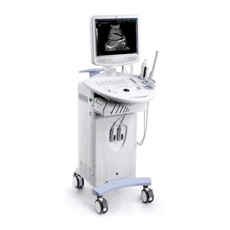
NOTE: For any question about choice and use of the printers, contact Mindray customer service department. System Introduction This section introduces the structure of the system, taking the system with CRT as example. -
Page 24: Introduction Of Each Unit
1.4.1 Introduction of Each Unit < 5 > < 6 > < 7 > < 9 > Front view Left side view 1-4 Overview... -
Page 25: I/O Panel
Name Function and Connection Monitor Displays images and parameters, etc. Hook for transducer cable Used for hanging the transducer cable. Transducer and gel bottle Used for holding the transducer or gel bottle holder provisionally. Printer area Used for mounting a printer. Video output Connects to the video input port of the video printer. -
Page 26: Control Panel
1.4.3 Control Panel <9> <1> <2> <3> <4> <5> <6> <7> <8> <16> <10> <11> <23> <24> <25> <20> <26> <27> <28> F.position Depth Zoom Rotation <22> <12> <30> Gain <13> <29> Name Function Patient Ends the current exam. Info Opens/closes the patient information dialog box. - Page 27 Name Function Press to switch among items and rotate to adjust the corresponding item: Depth: Adjusts the depth. Depth/Zoom /Rotation Zoom: Magnifies the image. Rotation: Rotates the arrow mark or the transducer mark of the body mark. Print Printing Switches between auto/manual cine review modes. Releases Cine the cursor.
-
Page 28: Symbols
1.4.4 Symbols This system uses the symbols listed in the following table, and their meanings are explained as well. Symbol Description Location Dangerous voltage Inside the machine Main switch OFF Power switch │ Main switch ON Serial number AC (Alternating current) Date of manufacture Label of the Manufacturer... -
Page 29: Preparing The System
Preparing the System This chapter introduces how to prepare and get familiar with the system. Setup and Connections 2.1.1 Moving and Placing the System Please read and understand the safety precautions before moving and placing the system. 1. Turn off the power and disconnect the peripheral devices. 2. -
Page 30: Connecting/Disconnecting The Transducers
NOTE: Use the transducer provided by Mindray only. Otherwise may damage the system and transducer or cause a fire. Connecting the transducer... -
Page 31: Connecting/Disconnecting Usb Device
Disconnecting the transducer Turn off the ultrasonic system or freeze the image. Turn the lock of the transducer connector counter-clockwise to release it. Pull the transducer connector straight out vertically. Settle the transducer appropriately. 2.1.4 Connecting/Disconnecting USB device DO NOT directly remove a USB memory device; otherwise the USB WARNING: memory device and / or the system may be damaged. -
Page 32: Connecting An External Display
If the system begins to function improperly – immediately stop scanning. If the system continues to function improperly – fully shut down the system and contact Mindray Customer Service Department or sales representative. If you use the system in a persistent improperly functioning state –... -
Page 33: Powering On
Items Result No miscellaneous odds and ends are allowed to be attached or affixed to the control panel. Check the power cord / power supply and all I / O ports. Ensure that all connections are free from damage and remain clear of foreign object blockages. There shall be no obstacles around the system and its air vent. -
Page 34: Powering Off
2.2.4 Powering OFF If you are not using the system for a long time, please shut down the system: 1. Put the transducer away. 2. Press the power switch to shut down the system. 3. Turn off all peripherals connected to the system. Main Interface The main interface is as above, and the functions of areas are listed below: Description... -
Page 35: Basic Operations
Description Depth scale Cine progress bar Current exam mode Prompt information Mark of current mode Current input method Result window of measuring mode Menu zone Date and time Image parameters, type of transducer, transmitting frequency and depth. is the frozen mark, which is displayed when frozen. -
Page 37: Beginning An Exam
Beginning an Exam This chapter introduces the basic procedures and operations of an ultrasonic exam. Entering Patient Information Although you can start scanning a patient without entering patient information, it is recommended to enter patient information before an examination is started. Before examining a new patient, press the [Patient] key to end the exam of CAUTION: the previous patient, update the patient ID and information, to avoid m... -
Page 38: Get Patient Information
Get Patient Information 3.2.1 iStation iStation is used to query patient information, in which the DICOM functions are only available for systems configured with DICOM software. To enter iStation: Press <Info> to open the “Patient Info” dialog box, and then click [iStation] to open the “iStation”. -
Page 39: Work List
3.2.2 Work List Work List is used to get patient information from the work list server. It is only available for systems configured with DICOM software. To open the “Work List” dialog box: Press <Info> to open the “Patient Info” dialog box, Click [Work List] in the “Patient Info”... -
Page 40: Adjusting The Image
M Mode M+B mode: Press to enter M+B mode. In M+B mode, roll the trackball to adjust the sample line. M Mode: After setting the sample line, press to enter M mode. Adjusting the Image 3.5.1 Zooming This system provides a zoom range of 100%~1000%. 1. -
Page 41: Rotating And Flipping The Image
3.5.3 Rotating and Flipping the Image Rotating the Image Check whether the menu corresponding to the current mode is open. If not, press <Menu> to open it. Move cursor to [Rotation (Angle)]. Then press <Set> to rotate the image clockwise 90 degrees, or press <Back>... -
Page 42: Cine Review Of B Mode
3.6.1 Cine Review of B Mode In the following conditions, the cine review memory will be cleared: Beginning a new exam Switching transducers (only the corresponding part is cleared in Dual B or Quad B mode) Switching among image modes Adjustment of some real-time image parameters (such as depth) Defreezing Manual Review... -
Page 43: Cine Review Of 2B/4B Mode
3.6.2 Cine Review of 2B/4B Mode In Dual B/Quad B mode, the cine memory is split into 2/4 correspondingly. The basic operations are the same as those in B mode, press or click [4B] in Freeze Menu to activate an image window and review. -
Page 44: Measurement Items
<Back>: During a measurement, press <Back> to cancel the last operation. Press <Back> continually to delete completed measurements in backward sequence. 3.7.2 Measurement Items The measurement library of this system provides Measurement, Calculate and Study items of General, Abdomen, Gynecology, Cardiac, Vascular, Urology, SmallPart, ORTH and Obstetric. You can select appropriate items to create measurement packages. -
Page 45: Optimizing The Image
Optimizing the Image This chapter introduces how to optimizing the image by adjusting the image parameters. Before optimizing the image by adjusting the image parameters, use the brightness and contrast knob to adjust the monitor to the best functional mode. The image parameters area is as follows: Acoustic B Image... -
Page 46: B Mode
B Mode 4.2.1 Depth Description Adjusts the image depth. Depth is available for B/M modes. Operations Depth, Zoom and Rotation share the same <Multifunctional Knob>. Press the <Multifunctional Knob> to switch among the items and rotate the knob to adjust the item when the corresponding indicator is lit up. -
Page 47: Gain
4.2.3 Gain Description B/M gain is intended to adjust the gain of the whole receiving system and the signal sensitivity of B/M image. The adjusting range is 0dB~100dB. B-mode and M-mode Gains are displayed in the Parameter Area on the top of the screen. Operations Rotate <Gain>... -
Page 48: Tgc
4.2.5 Description Ultrasonic wave attenuates when transmitting inside tissue, so the received signals of deeper tissue are weaker than those of superficial tissue. The system compensates the signals from deeper tissue by segments to make the image of deeper issue clear. Adjusting TGC (Time Gain Compensation) will amend the compensation. -
Page 49: B/M Dyn Rng (Dynamic Range)
4.2.7 B/M Dyn Rng (Dynamic Range) Description Adjusts contrast resolution of the B Mode image to compress or expand the gray display range. The range is 30dB~100dB and the step is 5. Operations Press <Menu> to open B Img Menu, and move cursor to [Dyn Rng (value)]. Press <Set>... -
Page 50: Tsi
4.2.10 Description Optimizes the image for different tissue: Operations Press <Menu> to open B Img Menu, and move cursor to [TSI (value)]. Press <Set> or <Back> to adjust TSI. General: It is helpful to scan the internal organs like liver, kidney, pancreas, thyroid, etc. -
Page 51: B/M Post Process
4.2.12 Description IP is the combination of “Dyn Rng (Dynamic Range)”, “Image Enhance” and “Frame Avg (Frame Average)”. The parameters can be configured separately. Operations Press <▲> and <▼> corresponding to “IP” to adjust IP. Effects The effect is relative with the parameters. Impacts The adjustment to IP will influence the cine review. -
Page 52: M Mode
Rejection Description Suppress the image signal below a certain gray scale. Operations 1. Click [Post Process] [Grey Rejection] of B or M image menu to open the “Grey Rejection” dialog box. 2. Move cursor to the “▲” node, and the cursor turns to “ ”. Press <Set> and roll the track ball to move the “▲”... -
Page 53: Edge Enhance
4.3.2 Edge Enhance Description The range of “Edge Enhance” is 0~4. 0 represents no Edge Enhance and 4 represents maximum Edge Enhance. Operations Press <Menu> to open M Img Menu, and move cursor to [Edge Enhance (value)]. Press <Set> to increase the Edge Enhance and press <Back> to decrease the Edge Enhance. -
Page 55: Annotating The Image
Annotating the Image This chapter introduces how to add comments and body mark to ultrasound image. Comments Comments can be added to real-time image, frozen image, cine review image and zoomed image. You must ensure that the entered comments are correct. Incorrect WARNING: comments may cause misdiagnosis! To enter comment status:... -
Page 56: Adding Arrow
Press <Set> to add the selected comment and end adding comments. The cursor moves to the end of the comments. Add comments from comments library (select word in the menu) Move cursor to where you want to add comments. Press <Set> to set the initial position. You can also move the comment later. -
Page 57: Adding Body Mark
5.2.1 Adding Body Mark Press <Body Mark> to open the “BodyMark Lib” dialog box. Move cursor to the desired body mark and press <Set> to add the body mark to the image. Roll the track ball to move the transducer mark and rotate the <Multifunctional Knob> to rotate the transducer mark. -
Page 59: Auxiliary Functions
Auxiliary Functions Biopsy Guide 6.1.1 Basic Operations WARNING: Do not freeze the image while performing biopsy. To enter biopsy mode: Press <Menu> to open the B image menu, and then click [Biopsy] to open the biopsy menu and enter biopsy mode. In M+B mode, you need to switch to B Img Menu. -
Page 60: Lithotrity
Lithotrity “Lithotrity” helps to locate the focus point of lithotrity wave during lithotrity treatment. By watching the procedure of lithotrity in real-time and adjusting the intension and frequency of the lithotrity wave, the harm to the patients can be reduced to the least. To use “Lithotrity”, please enable “Lithotrity”... -
Page 61: File Management
File Management Formats of Files File formats adopted by the diagnostic system only: FRM: System-defined single-frame static file format, non-compressed format, used for measurements and comments. CIN: System-defined multi-frame file format; you can perform manual or auto cine review, and perform measurements or add comments to the reviewed images. After you open stored a CIN file, the system automatically enters cine review status. -
Page 62: Backup
To delete a file/directory: Select a driver. Select the path. Select the file/directory to be deleted and click [Delete]. Click [OK] to confirm deleting, or click [Cancel] to cancel. To rename a file/directory: Select a driver. Select the path. Select the file/directory to be renamed and click [Copy]. Input the new name of the file/directory. -
Page 63: Erasing Optical Disc
3. Click [Backup] in the file manager to open the “Backup” dialog box. 4. Select a drive in the drop-down list of “Drive: ”. 5. To add/remove the file or folder to be backed up: (1) Click [+] in the front of a folder to extend it; (2) Select a file or a folder in the left list, and click [>] to add it to the right list. - Page 64 [Interval (time)]: To set the time interval of playback when “Auto Play” is selected. Click [ ] and [ ] to change the time interval. [Start]: To start playback. [Exit]: To exit iVision. Manual Playback If “Manual Play” is selected, press the directions < > and < > to play the images. To exit iVision When reviewing CIN files, press <Freeze>...
-
Page 65: Preset
To exit preset: Click [Return] in the preset menu to close the preset menu and exit preset. When the setup data is changed, be sure to save the preferences CAUTION: according to the methods described in this chapter. Mindray is not responsible for the loss of the setup data. Note: The Preset parameters take effect only after returning from Preset following the above operations. -
Page 66: Basic Operations
Basic Operations The basic operations of controls in Preset are as follows: Text box: Input text with the keyboard. Radio Button: Click the button to select an item. At least one and only can be selected. Check box: Click the check box to select it or deselect it. Selecting plural boxes and selecting none are both allowed. -
Page 67: General
8.2.2 General Sub-page Item Type Description Info displays in To select the items to be displayed in the Check box image banner patient information area. Patient H&W Unit Radio button To select the unit: Metric/English. Info To select the formula of surface area: Surface Formula Radio button Orient/West. -
Page 68: Meas Param
Sub-page Item Type Description To set the status when frozen in measurement Frozen when Radio button mode: Cine (to switch to cine review Measurement mode)/Measure (to keep measuring) Checked (enables lithotrity)/Unchecked Lithotrity Enable Check box (disables lithotrity) Checked (enables image Image Merge Check box merging)/Unchecked (disables image... -
Page 69: Key Config
Sub-page Item Type Description Exam To set the format of growth graphs: 1*1, 2*1 Trend Format Drop-down list Report and 2*2. Distance, Area, Volume, Time, Unit Drop-down list To select the unit of the results Velocity, Slope, Acceleration 8.2.5 To configure the formulas of Fetal Gestational Age, Fetal Growth and Fetal Weight. Refer to [Advanced Volume] for details. -
Page 70: Exam Preset
Panel Panel Function Available Functions Biopsy Line Display, M-Mark Display, Rotation, 4B, Other Clear, Exit, TSI, B, M, Dual, Freeze, Measure, Comment, Body Mark, Menu, Exam, None Keyboard preset: Item Type Description To set the volume of keyboard sound: Key Volume Drop-down list Low/High/None To set the speed of cursor when rolling the track... -
Page 71: Exam Config
8.3.2 Exam Config To select the applied part of exam modes: Click the cell corresponding to “Application” of each exam mode and select the applied part in the drop-down list. To copy parameters of an exam mode to another exam mode Select a source exam mode in the exam modes list. - Page 72 Item Type Description Drop-down list To set the default TSI. To configure the B Map/THI Map. Refer to the B Map/THI Map Button following segments for detailed operations. Depth Drop-down list To set the default depth. Checked/Unchecked: For transducers that support Check box harmonic, you can set harmonic as default frequency when this item is checked.
-
Page 73: Measure Preset
B/THI Map Click [B Map]/[ THI Map] to open the “Effect” dialog box. Select the grey map to be configured. Configure the “Grey Curve”, “Grey Rejection” and “γ” (please refer to “4.2.13 B/M Post Process” for details), or click “Record Current” to record the current parameters as preset. Click [OK] to confirm or click [Cancel] to cancel. -
Page 74: Comment Preset
[<]: Select a package in “Selected Items”, and click [<] to delete it; [<<]: Click [<<] to delete all packages in “Selected Items”; Sort: Select a package in “Selected Items”, and then click [Move Up] or [Move Down] to move it up/down. [Default]: Select a package in “Selected Items”, and then click [Default] to set it as the default measurement package of current exam mode;... -
Page 75: Comment Library
8.6.1 Comment Library Descriptions of abbreviations used in the comment library are as follows: Abdomen Abbreviation Description Abbreviation Description Rt Lobe Right Lobe of Liver Gall Bladder Lt Lobe Left Lobe of Liver Common Hepatic Duct Caudate Caudal Lobe Common Bile Duct Lig.teres Ligamentum Teres Hepatis Splenic A... - Page 76 Abbreviation Description Abbreviation Description Aortic Valve Prox Proximal Tricuspid Valve Middle Pulmonary Valve longitudinal Ant Mitral Leaflet Anterior Mitral Leaflet Transverse Abbreviation Description Abbreviation Description Gynecology Ca++ Calcify Endo Endometrium Right Rt Ovary Right Ovary Left Lt Ovary Left Ovary Prox Proximal Rt Kidney...
- Page 77 Urology Abbreviation Description Abbreviation Description Lt Seminal Lt Kidney Left Kidney Left Seminal Vesicle Vesicle Rt Seminal Rt Kidney Right Kidney Right Seminal Vesicle Vesicle Calices Renal Calices Rt Testicle Right Testicle Pyramid Renal Pyramid Lt Testicle Left Testicle Column Renal Column Right Renal A...
- Page 78 Abbreviation Description Abbreviation Description Middle Cerebral Artery Femoral Vein Posterior Cerebral Artery Saphenous Saphenous Vein Basilar A Basilar Artery Pop V Popliteal Vein Ax A Axillary Artery Tp-Trunk V Tibial Peroneal Trunk Vein Brahc A Brachial Artery Innom V Innominate Vein Ulnar A Ulnar Artery Sural V...
-
Page 79: Dicom
DICOM This item is only available for systems configured with DICOM. Before configuring DICOM, please read the DICOM CONFORMANCE STATEMENT of this system and SCPs such as PACS, RIS or HIS to make sure the SCU service is supported by the SCPs. System Name: It is the same as “AE Title”. -
Page 80: Manage Settings
Print Parameter Item Drop-down Copies Select or input the copies of files to be printed. list/Text box 8INX10IN, 8_5INX10IN, 10IN×12IN, 10IN×14IN, 11INX14IN, 11INX17IN, 14INX14IN, 14INX17IN, 24cm× Film Size Drop-down list 24cm, 24cm×30cm, A4, A3 Medium Type Drop-down list Paper, Clear Film, Blue Film Trim Drop-down list Yes, No... -
Page 81: Maintenance
[Export All]: To export all the items. [Import All]: To import all the items. [Restore Factory]: To restore all items to factory default. [Exit]: To exit. Maintenance The [Maintenance] is for updating of system software or other special requirements. Contact your service representative if necessary. -
Page 83: Cleaning And Maintaining The System
Cleaning and Maintaining the System This chapter introduces how to clean and maintain the system. 1. Only an authorized Mindray service engineer can perform maintenance not specified in this operator’s manual. WARNING: 2. For the sake of the system performance and safety, you should perform periodical checks for the system. -
Page 84: Backup Of Data
Consumables and Periodic Part Replacement This system contains some consumables and parts requiring periodic replacement. Before replacing them, please contact Mindray Customer Service Department or sales representative for instructions. Troubleshooting To ensure proper system operation and function, it is recommended that a maintenance and inspection plan be established to periodically check the safety of the system. - Page 85 Malfunction Potential Causes Corrective Measures After the power Abnormal power system or Verify that the plug has not supply is turned on, incorrect connection of the become loosened or dislodged the power indicator power cord. from the back of the system. does not light on.
-
Page 87: Acoustic Output
Acoustic Output This section of the operator’s manual applies to the overall system including the main unit, transducers, accessories and peripherals. This section contains important safety information for operators of the device, pertaining to acoustic output and how to control patient exposure through use of the ALARA (as low as reasonably achievable) principle. -
Page 88: Derated Ultrasonic Output Parameters
Additional information regarding the concept of ALARA and the possible bioeffects of Ultrasound is available in a document from the AIUM (American Institute of Ultrasound Medicine) title “Medical Ultrasound Safety”. 10.4 Derated Ultrasonic Output Parameters In order to determine the relevant Ultrasonic Output Parameters, a method is used which allows for the comparison of ultrasound systems which operate at different frequencies and are focused at different depths. -
Page 89: Acoustic Power Setting
10.7 Acoustic Power Setting Adjusting Acoustic Power Acoustic power can be set in the range from 0 to 15, where 0 represents minimum acoustic power and 15 represents maximum acoustic power. Press <Menu> to open the image menu. Move the cursor to [A.power (Value)]. Press <Set> to increase the acoustic power and press <Back>... -
Page 90: 10.9 References For Acoustic Power And Safety
Operations Affections on Acoustic Output Changing the operating frequency changes the focal characteristics of Changing frequency the acoustic waves, thus changes the acoustic output power. Changing the number of acoustic lines generated (line density) affects Line density the acoustic output power. Since the system and user presets contain all of the above imaging Preset parameters, changing the preset will change the acoustic output power. -
Page 91: Appendix A Transducer Maximum Surface Temperature
ISO Guide to the Expression of uncertainty in measurement. Three transducer samples have been tested and the confidence coefficient is at 95%, the value of is 4.30. The measurement data were obtained under the test conditions employed at Mindray. Maximum surface Maximum surface Transducer model temperature (°C) -
Page 93: Appendix B Accuracy Of Measurement
Appendix B Accuracy of Measurement Within the selected field range, the measurement accuracy is ensured within the range mentioned above. The accuracy specifications are performance in the worst conditions, or based on the real test for the system. Depth and time Item Error range ≤±4% of full scale... -
Page 95: Appendix C Safety Classification
Appendix C Safety Classification Standard of Classification Type of Product According to the type of protection against CLASS I EQUIPMENT electric shock According to the degree of protection EQUIPMENT WITH TYPE-BF APPLIED against electric shock PARTS Degree of protection against harmful ingress Enclosure: IPX0, transducers: IPX7, foot of water switch: IPX8. -
Page 97: Appendix D Guidance And Declaration
1, 2, 3, and 4 below. Table 1: GUIDANCE AND MINDRAY DECLARATION—ELECTROMAGNETIC EMISSIONS This system is intended for use in the electromagnetic environment specified below. The customer or the user of this system should assure that it is used in such an environment. - Page 98 Table 2: GUIDANCE AND MINDRAY DECLARATION—ELECTROMAGNETIC IMMUNITY This system is intended for use in the electromagnetic environment specified below. The customer or the user of this system should assure that it is used in such an environment. IMMUNITY IEC 60601...
- Page 99 Table 3: GUIDANCE AND MINDRAY DECLARATION—ELECTROMAGNETIC IMMUNITY This system is intended for use in the electromagnetic environment specified below. The customer or the user of this system should assure that it is used in such an environment IMMUNITY IEC 60601-1-2...
- Page 100 Table 4 : RECOMMENDED SEPARATION DISTANCES BETWEEN PORTABLE AND MOBILE RF COMMUNICATION AND THIS SYSTEM This system is intended for use in an electromagnetic environment in which radiated RF disturbance are controlled. The customer or the user of This system can help prevent electromagnetic interference by maintaining a minimum distance between portable and mobile RF communication equipment (transmitters) and This system as recommended below, according to the maximum output power of the communication equipment.
- Page 101 P/N: 046-000308-00 (V1.1)
Need help?
Do you have a question about the DP-8500 and is the answer not in the manual?
Questions and answers