Table of Contents
Advertisement
Advertisement
Table of Contents
Troubleshooting

Subscribe to Our Youtube Channel
Related Manuals for Mindray DPM 4


Summary of Contents for Mindray DPM 4
- Page 3 Mindray DS USA, Inc. (hereinafter called Mindray DS) owns the intellectual property rights to this product and this manual. This manual may refer to information protected by copyrights or patents and does not convey any license under the copyright and patent rights of Mindray DS, nor the rights of others.
- Page 4 Responsibility on the Manufacturer Party All information contained in this manual is believed to be correct. Mindray DS shall not be liable for errors contained herein nor for incidental or consequential damages in connection with the furnishing or use of this manual.
- Page 5 Once being polluted by liquid, they must be thoroughly dried. If to further remove the pollution, please contact your biomedical department or Mindray DS. It is important for the hospital or organization that employs this equipment to carry out a reasonable maintenance schedule.
- Page 6 Exemptions Mindray DS 's obligation or liability under this warranty does not include any transportation or other charges or liability for direct, indirect or consequential damages or delay resulting from the improper use or application of the product or the use of parts or accessories not approved by Mindray DS or repairs by people other than Mindray DS authorized personnel.
- Page 7 Return Policy Return Procedure In the event that it becomes necessary to return this product or part of this product to Mindray DS, the following procedure should be followed: Return authorization: Contact the Customer Service Department and obtain a Customer Service Authorization number.
- Page 8 Safety Precautions Meaning of Signal Words In this service manual, the signal words WARNING, CAUTION and NOTE are used to indicate safety and other important instructions The signal words and their meanings are defined as follows. Signal word Meaning Indicates a potentially hazardous situation which, if not avoided, could WARNING result in death or serious injury.
- Page 9 CAUTION 1. Malfunctions due to radio waves Use of radio-wave-emitting devices near the monitor may interfere with its operation. Do not bring or use devices which generate radio waves, such as cellular telephones, transceivers, and radio controlled toys, in the room where the system is installed.
- Page 10 FOR YOUR NOTES VIII...
-
Page 11: Table Of Contents
Contents 1 About the Product ......................1-1 1.1 Introduction........................1-1 1.2 Application ........................1-1 1.2.1 General ....................... 1-1 1.2.2 Usage........................1-2 2 Principles........................... 2-1 2.1 General ..........................2-1 2.1.1 Parameter Measurement..................2-2 2.1.2 Main Control Part....................2-2 2.1.3 Man-Machine Interface ..................2-2 2.1.4 Power Supply ..................... - Page 12 3.2 Environmental Specifications ..................3-1 3.3 Power Source Specifications................... 3-2 3.4 Hardware Specifications ....................3-3 3.5 Wireless network......................3-4 3.6 Data Storage ........................3-4 3.7 Signal Output Specifications................... 3-4 3.8 ECG Specifications ......................3-5 3.9 RESP Specifications...................... 3-12 3.10 SpO Specifications.....................
- Page 13 5.1.9 Watertrap ......................5-4 5.1.10 Recorder ......................5-5 5.1.11 Power Supply ....................5-5 5.1.12 Clock ........................ 5-5 5.1.13 System Test ...................... 5-5 5.2 NIBP Calibration......................5-6 5.3 IBP Calibration........................ 5-7 5.3.1 IBP Transducer Zero ..................5-7 5.4 DPM4 Material List .......................5-11 6 Maintenance and Cleaning....................
- Page 14 FOR YOUR NOTES...
-
Page 15: About The Product
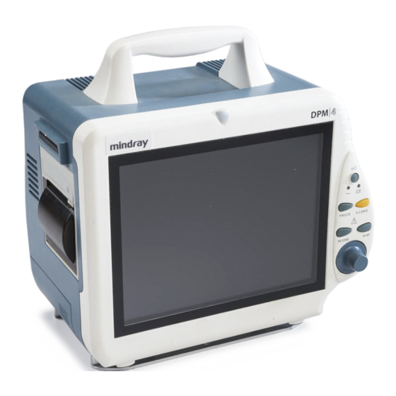
About the Product 1.1 Introduction The DPM4 Patient Monitor, a portable and accessible patient monitor, which applies to adults, pediatric and neonates, is supplied by rechargeable battery or external AC power. You can select different configurations as required. Besides, the DPM4 can be connected with the central monitoring system whereby a monitoring network will be formed. -
Page 16: Usage
1.2.2 Usage DPM4 converts physiological signals to digital signals, processes them and displays them on the screen. You can set the alarm limit as required. When the monitored parameter exceeds the preset alarm limit, the patient monitor will start the alarm function. In addition, you can control the patient monitor through the control panel. -
Page 17: Principles
Principles 2.1 General The intended use of the DPM4 patient monitor is to monitor a fixed set of parameters including ECG, RESP, SpO2, NIBP, TEMP, IBP, and CO2 (IBP and CO2 are optional). It consists of the following functional parts: Parameter measurement;... -
Page 18: Parameter Measurement
2.1.1 Parameter Measurement The parameter measurement and monitoring are the core functions of the patient monitor. The parameter measurement part of the DPM4 patient monitor consists of the measurement probe, parameter input socket assembly, NIBP assembly and the main control board. This part converts the physiological signals to electrical signals, processes those signals and conducts the calculation by the preset program or command delivered from the main control board, and then sends the values, waveforms and alarm information (which will be displayed by... -
Page 19: Power Supply
2.1.4 Power Supply The power supply part is an important part of the patient monitor. It includes the main power PCB, backlight board, batteries and fan. The main power PCB converts the external AC current to the 5V DC current, which are supplied for the whole system. -
Page 20: Main Board
The DPM4 PCB connection is shown in the following figure. Figure 2-3 PCB connection Basic functions and working principles of modules are described in the following sections. 2.2.1 Main Board 2.2.1.1 General The main board is the heart of the patient monitor. It implements a series of tasks, including the system control, system scheduling, system management, data processing, file management, display processing, printing management, data storage, system diagnosis and alarm. - Page 21 2.2.1.2 Principle diagram Figure 2-4 Working principle of the main board 2.2.1.3 Principle The main board is connected with external ports, including the power input port, multi-way serial port, TFT display interface, analog VGA interface, network port and analog output port. Besides, on the main board is also a BDM interface reserved for the software debugging and software downloading.
-
Page 22: Ecg/Resp/Temp Module
Analog Output The D/A converter converts the digital ECG/IBP signals sent from CPU to the analog signals, which are provided for the external after low-pass filtered by the filter and amplified by the amplifier. FPGA and VRAM VRAM stores the displayed data. CPU stores the displayed data to VRAM through FPGA. FPGA gets data from VRAM, processes them, and then sends them to the relevant graphic display device. - Page 23 2.2.2.2 Principle diagram Figure 2-5 Working principle of the ECG/RESP/TEMP module 2.2.2.3 Principle This module collects the ECG, RESP and TEMP signals through the transducer, processes the signals, and sends the data to the main board through the serial port. ECG Signal Input Circuit The input protection and filtering circuits receive the ECG signal from the transducer, and filter the high-frequency interference signal to protect the circuit against the damage by defibrillator...
- Page 24 ECG Signal Process Circuit The difference amplifying circuit conducts the primary amplification of the ECG signal and rejects the common-mode interference signal. The low-pas filtering circuit filters the high-frequency interference signal beyond the frequency band of the ECG signal. The PACE signal refers to the ECG pace signal. It has significant interference to the ECG signal detection.
-
Page 25: Ibp Module
The main amplifying/filtering circuit conducts the secondary amplification of the RESP signal, filters the signal, and then sends it to the A/D conversion part. The A/D conversion part converts the analog signal to the digital signal, and sends the signal to CPU for further processing. - Page 26 2.2.3.3 Principle This module collects the IBP signal through the transducers, processes it and sends it to the main board throgh the serial port. IBP Signal Process Network The IBP signal is the differential signal. After the common-mode filtering, the difference signal is amplified by the difference amplifying circuit which changes the dual-end signal to the single-end signal.
-
Page 27: Spo 2 Module
2.2.4 SpO Module 2.2.4.1 General This module provides the function of measuring the Pulse Oxygen Saturation (SPO 2.2.4.2 Principle diagram Figure2-7 Working principle of the SpO2 module 2.2.4.3 Principle The SpO2 measurement principle Collecting the light signal of the red light and infrared transmitting through the finger or toe which is pulsing;... - Page 28 The biasing circuit adjusts the dynamic range of the signal, and sends it to the A/D conversion part. The A/D conversion part converts the analog signal to the digital signal, and then sends it to CPU for further processing. The D/A conversion part converts the digital signal received from CPU to the analog signal, and provides the control signal for the Led Drive Circuit and SPO2 Signal Process Network.
-
Page 29: Nibp Module
2.2.5 NIBP Module 2.2.5.1 General This module provides the function of measuring the Non-Invasive Blood Pressure (NIBP) parameter. 2.2.5.2 Principle diagram Figure 2-8 Working principle of the NIBP module 2.2.5.3 Principle The NIBP is measured based on the pulse vibration principle. Inflate the cuff which is on the forearm till the cuff pressure blocks the arterial blood, and then deflate the cuff according to a specified algorithm. - Page 30 Valve Drive Circuit This circuit controls the status (ON/OFF) of valves. It, together with the Motor Drive Circuit, implements the inflation and deflation of the cuff. Motor Drive Circuit This circuit controls the action of the air pump. It, together with the Valve Drive Circuit, implements the inflation and deflation of the cuff.
-
Page 31: Recorder Module
2.2.6 Recorder Module 2.2.6.1 General This module is used to drive the heat-sensitive printer. 2.2.6.2 Principle diagram Figure 2-9 Working principle of the recorder module 2.2.6.3 Principle This module receives the to-be-printed data from the main board, converts them to the dot matrix data, sends them to the heat-sensitive printer, and drives the printer. -
Page 32: Button Panel
2.2.7 Button Panel 2.2.7.1 General This module provides a man-machine interactive interface. 2.2.7.2 Principle diagram Figure 2-10 Working principle of the button panel 2.2.7.3 Principle This module detects the input signals of the button panel and control knob, converts the detected input signals to codes and then sends to the main board. -
Page 33: Power Pcb
Watchdog When powered on, the Watchdog provides the reset signal for CPU. The patient monitor provides the watchdog timer output and voltage detection functions. 2.2.8 Power PCB 2.2.8.1 General This module provides DC working current for other boards. 2.2.8.2 Principle diagram Figure 2-11 Working principle of the power PCB 2.2.8.3 Principle This module can convert 220V AC/12V DC or the battery voltage to 5V DC and 12V DC... - Page 34 Battery Control Circuit When the AC voltage and batteries coexist, this circuit controls the process of charging the batteries with the DC voltage converted by the AC/DC part. When the AC voltage is unavailable, this circuit controls the batteries to supply power for the subsequent circuits. 5V DC/DC This part converts the DC voltage to the stable 5V DC voltage and supplies it for the external boards.
-
Page 35: Software Description
2.3 Software Description 2.3.1 General Figure 2-12 System function As shown in Figure 2-12, in the red frame is the software system, on the left to the red frame are the inputs of the software system, and on the right to the red frame are the outputs. The parameter measurement module exchanges data with the software through the serial port, while the user interacts with the system through the button panel. -
Page 36: System Task
2.3.2 System Task Task Function Period In case of a System initialization Initializing the system startup Data processing Analyzing and saving the data 1 second Display of timer Implementing the timed refreshing 1 second information In case of a Switchover of modules Switching over between waveforms and screen change and screens... -
Page 37: System Function
2.3.3 System Function The system tasks can be classified as follows. Figure 2-13 System task 2-21... -
Page 38: System Parameter
2.4 System Parameter 2.4.1 General For the DPM4 patient monitor, signals are collected by modules, and the results are transferred to the main board through the adapter board, thus to process and display the data and waveforms. Commands from the main board, as well as the status information of modules, are transferred through the adapter board. -
Page 39: Ecg/Resp
2.4.2 ECG/RESP The DPM4 patient monitor has the following ECG functions: Lead type: 3-lead, 5-lead, 12-lead Lead way: 3-lead (1 channel): I, II, III 5-lead (2 channels): I, II, III, aVR, aVL, aVF, V 12-lead (8 channels): I, II, III, aVR, aVL, aVF, V1-V6, CAL Floating input Right-foot drive Lead-off detection... -
Page 40: Nibp
RESP The DPM4 patient monitor measures the RESP based on the impedance principle. While a man is breathing, the action of the breast leads to impedance changes between RL and LL. Change the high-frequency signal passing the RL and LL to amplitude-modulation high-frequency signal (AM high-frequency signal), which is converted to the electric signal after being detected and amplified and then sent to the A/D converter. -
Page 41: Spo2
2.4.4 SpO2 The SpO2 value is obtained through the pulse waves of the finger tips based on specific algorithm and clinical data. The SpO2 probe is the measurement transducer. It has two inbuilt LEDs and an inbuilt light receiver. The two LEDs include one red-light diode and one infrared diode, which emit light in turns. -
Page 42: Ibp
2.4.6 IBP The IBP module can monitor the arterial pressure, central venous pressure and pulmonary arterial pressure. Measurement principle: Introduce a catheter, of which the external end is connected to the pressure transducer, into the blood vessel under test, inject the physiological saline. Since the liquid can be transferred by pressure, the pressure inside the blood pressure is transferred by liquid to the pressure transducer, and the dynamic waveform of the pressure inside the blood pressure is obtained in real time. -
Page 43: Product Specification
Product Specification 3.1 Safety Classifications Class I with internal electric power supply. Type of protection against Where the integrity of the external protective earth (ground) in electric shock the installation or its conductors is in doubt, the equipment shall be operated from its internal electric power supply (batteries). Sidestream, Microstream CO2: BF (defibrillation proof) Degree of protection... -
Page 44: Power Source Specifications
3.3 Power Source Specifications AC Power Supply Specifications Input voltage 100 to 240 V~ Current 1.1A to 0.5A Frequency 50/60 Hz Fuse T 3.15 A, 250 V Internal battery Number of batteries Battery type Sealed lead-acid battery or lithium-ion battery Time to shutdown >5 min (after the first low-power alarm) Sealed lead-acid battery... -
Page 45: Hardware Specifications
3.4 Hardware Specifications Physical Size 261 × 240 × 171mm (width×height×depth) Weight < 5 kg (With no accessory and battery) Display Type Color TFT LCD Size 8.4 inches (diagonal) Resolution 800×600 pixels Recorder Type Thermal dot array Horizontal resolution 160 dots/cm (at 25 mm/s recording rate) Vertical resolution 80 dots/cm Width of the recorder paper... -
Page 46: Wireless Network
3.5 Wireless network Standards IEEE 802.11b, Wi-Fi compatible Frequency range 2.412 to 2.462GHz China America Canada Europe Spain France Japan Operating channel 1 to 11 10, 11 For other country, please refer to your local law. Safe distance 10m (a circle centering AP with the diameter of 10m) Maximum data rate 11Mbps 3.6 Data Storage... -
Page 47: Ecg Specifications
Signal RGB: 0.7 Vp-p/75Ω; Horizontal/vertical synchronization: TTL level 3.8 ECG Specifications Mindray DS Software Package Lead naming style AHA, EURO The lead resistance is no greater than 51 kΩ and it is in parallel with a 0.047 µF capacitor, it will not cause a lead fault condition. - Page 48 Monitor mode: 0.5 to 40 Hz Surgery mode: 1 to 20 Hz Diagnostic mode: ≥90 dB Monitor mode: ≥105 dB Common mode rejection Surgery mode: ≥105 dB (The notch filter is turned off.) 50/60Hz Notch The monitor provides software filtering against the 50/60HZ Filtering industrial frequency.
- Page 49 Precision ±1 bpm or ±1%, whichever is greater. Trigger threshold level 200 μV (lead II) Trigger indication There will be an audible beep on every beat captured. Heart Rate Averaging The average Heart Rate is computed in line with the ANSI/AAMI EC13 Section 4.1.2.1 d) as follows: When the last 3 R-to-R intervals >...
- Page 50 Pace pulse Pace pulses meeting the following conditions are marked by the PACE indicator. Pulse indicator Amplitude: ±4 to ±700 mV (3/5-lead) Width: 0.1 to 2 ms Rise time: 10 to 100 µs When tested in accordance with the ANSI/AAMI EC13 Sections 4.1.4.1 and 4.1.4.3, the heart rate meter rejects all pulses meeting the following conditions.
- Page 51 Diagnostic mode: ≥90 dB Monitor mode: ≥105 dB Common mode rejection Surgery mode: ≥105 dB (The notch filter is turned off.) 50/60Hz Notch Filtering The monitor provides software filtering against the 50/60HZ industrial frequency. In monitor and surgery modes, the 50/60HZ filter will be turned on automatically.
- Page 52 Trigger indication There will be an audible beep on every beat captured. Heart Rate Averaging The average Heart Rate is computed in line with the ANSI/AAMI EC13 Section 4.1.2.1 d) as follows: The average heart rate is calculated on the basis of the mean RR-interval of the last 16 beats, unless the heart rate calculated using the last 4 beats is less than or equal to 48, then this rate is used.
- Page 53 When tested in accordance with the ANSI/AAMI EC13 Sections 4.1.4.1 and 4.1.4.3, the heart rate meter rejects all pulses meeting the following conditions. Amplitude: ±2 to ±700 mV Pulse rejection Width: 0.1 to 2 ms Rise time: 10 to 100 µs Min.
-
Page 54: Resp Specifications
3.9 RESP Specifications Measurement technique Thoracic impedance Lead Optional: lead I and lead II; default lead II Respiration excitation < 300 µA, sinusoid, 62.8 kHz (±10%) waveform Respiration impedance test 0.3 to 3 Ω range Baseline impedance range 200 to 2500 Ω (using an ECG cable with 1kΩ resistance) Differential input >... -
Page 55: Spo 2 Specifications
3.10 SpO Specifications Mindray DS SpO2 Module All SpO sensors specified in the section Mindray DS SpO2 Accessories meets the following specifications when used with Mindray DS SpO2 module. SpO2 Measurement range 0 to 100% Resolution 70 to 100%: ±2 % (adult/pediatric, non-motion conditions) - Page 56 Masimo SpO Module All SpO sensors specified in the section Masimo SpO2 Accessories meets the following specifications when used with Masimo SpO module. SpO2 Measurement range 1 to 100% Resolution 70 to 100%: ±2% (adult/pediatric, non-motion conditions) 70 to 100%: ±3% (neonate, non-motion conditions) Precision 70 to 100%:...
-
Page 57: Nibp Specifications
Nellcor SpO Module All SpO sensors specified in the section Nellcor SpO2 Accessories meets the following specifications when used with Nellcor SpO module. Sensor Range Precision* 70 to 100% ±2% MAX-A, MAX-AL, MAX-N, MAX-P, MAX-I and MAX-FAST 0% to 69% Undefined 70 to 100% ±2.5%... -
Page 58: Temp Specifications
Maximum average error: ±5mmHg Measurement precision Maximum standard deviation: 8mmHg Resolution 1mmHg Static pressure 0 to 300mmHg measurement range Static accuracy ± 3 mmHg Adult: 297±3 mmHg Over-pressure protection Pediatric: 240±3 mmHg by software Neonate: 147±3 mmHg Adult: 330 mmHg Over-pressure protection Pediatric: 330 mmHg... -
Page 59: Ibp Specifications
3.13 IBP Specifications Number of channels Pressure readings Systolic, diastolic, mean pressures and PR Pressure labels ART, PA, CVP, RAP, LAP, ICP, P1 and P2 Linear input range will be -50 to﹢300 mmHg, after zeroing. 0 to 300 mmHg -6 to 120 mmHg Measurement range CVP/RAP/LAP/ICP -10 to 40 mmHg... -
Page 60: Specifications
Measurement technique Infrared absorption technique Displayed parameter EtCO2, FiCO2, Respiration Rate Meet the requirements of EN ISO 21647/ISO 21647 and CO2 function ISO9918. Mindray DS CO Specifications CO2 measurement range 0 to 99mmHg 0 to 40 mmHg: ±2 mmHg Precision* 41 to 76 mmHg: ±5%... - Page 61 <5 s @ 100 ml/min <6.5 s @ 70 ml/min Apnea alarm delay AwRR: 10 to 40 s * Conditions for measurements in typical precision: The measurement is started after the preheating mode of the module; Ambient pressure: 750 mmHg to 760 mmHg; room temperature: 22℃ to 28℃; The gas under test is dry, and the balance gas is N2;...
- Page 62 * Precision applies for breath rates of up to 80 bpm. For breath rates above 80 bpm, accuracy complies with EN ISO 21647/ISO 21647/ISO 9918 (4 mmHg or ±12% of reading whichever is greater) for EtCO2 values exceeding 18 mmHg. To achieve the specified accuracies for breath rates above 60 breaths/minute, the Microstream®...
-
Page 63: Disassembling/Assembling & Troubleshooting
Disassembling/Assembling & Troubleshooting 4.1 DPM4 Disassembling/Assembling 4.1.1 Exploded View of DPM4 Figure 4-1 Exploded view of DPM4 Material code Part & Specification Quantity 115-001437-00 Front bezel assembly 8002-30-36161 Screen assembly M04-002505--- Cross-head screw M3*6 M04-000104--- Elastic gasket GB93 3 8002-30-36185 Main Unit 115-000121-00 TR60 Recorder... -
Page 64: Dpm4 Front Bezel Assembly
8002-30-36209 CF Card assembly M04-000305--- Self-tapping screw PT3X12 8002-30-36342 Back housing assembly 8002-30-36378 Back housing assembly (supporting wireless network adapter) 8002-30-36204 Parameter connector assembly(with CO2) M04-004015--- Gasketed cross-head screw M3*8 8002-21-36169 Parameter connector panel(with CO2) 8002-20-36222 Parameter connector label(with CO2) 9211-30-87429 Water trap assembly M04-051003---... - Page 65 Material code Part & Specification Quantity 8000-20-10290 Anti-glare mask 8002-20-36238 Alarm indicator mask 043-000087-00 Front bezel 8002-20-36265 Dust washer 8001-30-25667 Alarm indicator board 8000-20-10193 Key plate 8002-30-36165 Keyboard M04-051003--- Self-tapping screw PT2X6 0010-30-43089 Encoder board 8000-20-10194 Rubber button 8000-20-10220 feet 9201-20-35972 Knob...
-
Page 66: Dpm4 Back Housing Assembly (Lithium Battery)
4.1.3 DPM4 Back Housing Assembly (Lithium Battery) Figure 4-3 DPM4 back housing assembly Material code Part & Specification Quantity 8002-20-36167 Back housing 8000-20-10339 Sealed cushion for back housing 8000-20-10220 Feet 8002-20-36219 Battery Door bond M04-000802--- Pad GB97.1 3 M04-003105--- Self-tapping screw PT3X8 8002-20-36217 Speaker press plate 8002-20-36218... -
Page 67: Screen Assembly
8002-20-36224 Fan cushion 8002-20-36237 Handle 8002-20-36174 Battery door 4.1.4 Screen Assembly Figure 4-4 Screen assembly Material code Part & Specification Quantity M04-002405--- Cross-head screw M2X6 900E-10-04913 INVERTOR 'TDK'' 0010-10-12358 TFT screen 8.4"(800X600) 8000-20-10217 Stud screw for screen 8000-20-10231 Sponge cushion1 8002-20-36175 Screen supporter 8000-20-10232... -
Page 68: Battery Connector Assembly
4.1.5 Battery Connector Assembly Figure 4-5 Battery Connector assembly Material code Part & Specification Quantity M04-000301--- Nut GB6170 M3 M04-004013--- Gasketed cross-head screw M3X10 8002-30-36226 Lithium battery board M04-002505--- Cross-head screw GB818-85 M3X6 M04-030030--- Stud M3X12 9201-20-36038 Spring... -
Page 69: Parameter Connector Assembly
4.1.6 Parameter Connector Assembly Figure 4-6 Parameter connector assembly Material code Part & Specification Quantity M04-051003--- Self-tapping screw PT2X6 0010-10-12279 ECG connector 0010-21-12306 6PIN SPO2 Cable 8002-21-36171 Panel for parameter connector(with CO2) 0010-20-12194 NIBP Connector 6200-20-11614 Exhaust 9000-20-07459 Nut for Temp connector M04-000501--- Nut GB6170 M5 6000-10-02010... -
Page 70: Cf Card Assembly
4.1.7 CF Card Assembly Figure 4-7 CF card assembly Material code Part & Specification Quantity 8002-20-36196 CF model card 8002-20-36172 CFcard housing 8002-30-36192 CFconnector board 8002-20-36173 CFcard housing hook... -
Page 71: Troubleshooting
4.2 Troubleshooting 4.2.1 4.2.1 Black Screen, Startup Failure Figure 4-7 Location flow of faults causing black screen... -
Page 72: White Screen & Other Abnormal Screen
4.2.2 White Screen & Other Abnormal Screen In case of faults causing white screen or other abnormal screens, Check whether the LCD connection wires are in good contact; Replace the LCD connection wires, or replace the LCD if necessary; Replace the main control board if the fault still exists. 4.2.3 Encoder Faults If all other functions (indicator, alarm, buttons) of the button panel are normal, proceed to step 2;... -
Page 73: Test And Material List
Test and Material List 5.1 Test Procedure 5.1.1 5.1.1 Connection and Checking Connect the simulators, power supply and test fixture properly to the DPM4 patient monitor, and power it on. Then, the patient monitor displays the start-up screen on the TFT screen and enters the system screen. -
Page 74: Temperature
RESP measurement: Set the baseline impedance to 1K, the respiration impedance to 0.5Ω and 3Ω, and the respiration rate to 30 and 120. The respiration rate should be 29 – 31, 118 –122. PVC test: Set the simulator to the PVC mode, and set the occurrence times. The relevant PVCS should be obtained. -
Page 75: Spo2
5.1.6 SpO2 Select PLETH as the HR source of DPM4, and put the finger into the SpO sensor. The screen should display the PR and SpO values normally. The normal SpO value is above 97%. 5.1.7 IBP Test fixture Physiological signal simulator Test procedure ①... -
Page 76: Co2
5.1.8 CO2 Test fixture CO2 steel bottle (containing 10% CO2) Test procedure ①Sidestream CO2 measurement: Set the calculation compensation of DPM4 to COMMON. Plug the water trap to the water trap socket, connect the sampling tube with the CO2 steel bottle, and open//close the valve of the CO2 steel bottle based on the interval of 3s. -
Page 77: Recorder
5.1.10 Recorder Print the ECG waveform. The recorder should print it normally and clearly. Set the recorder to the fault of lack of paper and abnormal clip. There should be relevant prompting messages on the main screen. When the fault is cleared, the patient monitor should become normal. -
Page 78: Nibp Calibration
5.2 NIBP Calibration Figure 5-1 NIBP Calibration Calibration method: Based on the precision of 50mmHg (6.7kPa), increase the pressure step by step. The maximum error at any pressure point within the NIBP measurement range of the patient monitor should be no more than ±3mmHg (±0.4kPa). -
Page 79: Ibp Calibration
Calibration 5.3.1 IBP Transducer Zero Press the ZERO button on the IBP module to call up IBP PRESSURE ZERO menu as shown below: Figure 5-2 IBP PRESSURE ZERO Zero Calibration of Transducer Select CH1, the system will zero IBP1. Select CH2, the system will zero IBP2. Cautions:( Use the PM-6000 IBP module as a example) Turn off patient stopcock before you start the zero procedure. - Page 80 Figure 5-3 IBP Zero IBP Calibration Press CAL button on the IBP module to call up the IBP PRESSURE CALIBRATE menu as shown below: Figure 5-4 IBP Calibration Menu...
- Page 81 Calibrate the transducer: Turn the knob to select the item CH1 CAL VALUE, press and turn the knob to select the pressure value to be calibrated for channel 1. Then turn the knob to select the item CALIBRATE to start calibrating channel 1.
- Page 82 The Calibration Procedure: Close the stopcock that was open to atmospheric pressure for the zero calibration. Attach the tubing to the sphygmomanometer. Ensure that connection that would lead to patient is off. Connect the 3-way connector to the 3-way stopcock that is not connected to the patient catheter.
-
Page 83: Dpm4 Material List
5.4 DPM4 Material List Material Code Name & Specification 115-001437-00 Front bezel assembly 043-000087-00 Front bezel 8002-30-36342 Back housing assembly 8002-30-36378 Back housing assembly (supporting wireless network adapter) 8002-20-36167-51 Back housing 8002-20-36167-52 Back housing (supporting wireless network adapter) 0010-10-12358 TFT Screen 8.4"(800X600) 8002-30-36209 CF Card Module 9210-30-30150... - Page 84 FOR YOUR NOTES 5-12...
-
Page 85: Maintenance And Cleaning
All checks in which the patient monitor should be disassembled should be done by qualified maintenance personnel. The safety and maintenance checks can be done by Mindray DS engineers. The local office of Mindray DS at your region will be pleased to provide you with the information about the maintenance contract. -
Page 86: Cleaning
6.2 Cleaning Do switch off the patient monitor and disconnect the AC power supply before cleaning it or the probes. The patient monitor should be dust free. To clean the surface of its enclosure and screen, use the cleaning agent that is not corrosive, for example, soap and water. Do not use strong solvent, such as acetone;... - Page 88 Mindray DS USA, Inc. 800 MacArthur Blvd. Mahwah, New Jersey 07430 Tel:1.800.288.2121 Tel:1.201.995.8000 www.mindray.com P/N: 046-000181-00(3.0)
Need help?
Do you have a question about the DPM 4 and is the answer not in the manual?
Questions and answers