Sign In
Upload
Manuals
Brands
Mindray Manuals
Diagnostic Equipment
DP-50T
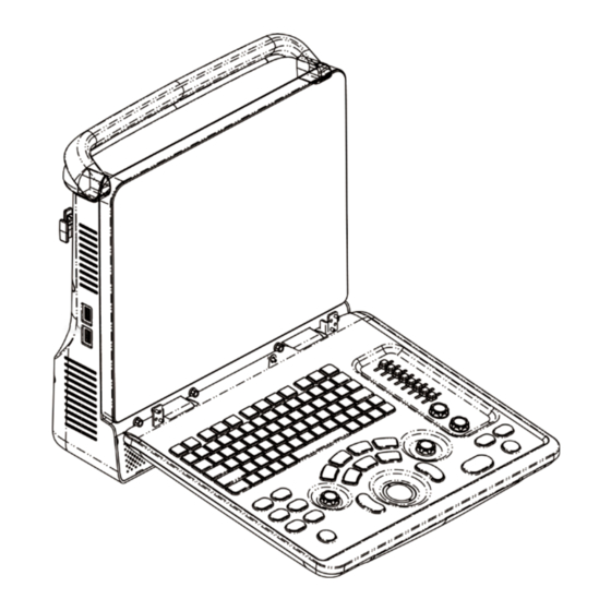
User Manuals: Mindray DP-50T Ultrasound System
Manuals and User Guides for Mindray DP-50T Ultrasound System. We have
3
Mindray DP-50T Ultrasound System manuals available for free PDF download: Operator's Manual, Service Manual
Mindray DP-50T Operator's Manual (261 pages)
Digital Ultrasonic Diagnostic Imaging System
Brand:
Mindray
| Category:
Medical Equipment
| Size: 8 MB
Table of Contents
Table of Contents
3
Intellectual Property Statement
11
Responsibility on the Manufacturer Party
11
Warranty
12
Exemptions
12
Customer Service Department
12
Important Information
13
About this Manual
14
Notation Conventions
14
Operator's Manuals
14
Manuals on Paper
14
Software Interfaces in this Manual
15
Conventions
15
Product Differences
15
Safety Precautions
17
Safety Classification
17
Meaning of Signal Words
18
Meaning of Safety Symbols
18
Safety Precautions
19
Latex Alert
27
Warning Labels
28
System Overview
29
Intended Use
29
Contraindication
29
Product and Model Code
29
Product Specifications
29
Imaging Mode
29
Power Supply
30
Environmental Conditions
30
Size and Weights
30
System Configuration
30
Standard Configuration
30
Probes Available
30
Options
32
Peripherals Supported
33
Introduction of each Unit
33
I/O Panel
35
Power Supply Panel
36
Control Panel
37
Symbols
39
System Preparation
41
Moving / Positioning the System
41
Power Supply
41
Connecting External Power Supply
41
Powered by Battery
41
Powering ON/ off
42
Powering on
42
Powering off
43
Connecting / Disconnecting a Probe
44
Connecting a Probe
44
Disconnecting a Probe
44
Connecting the Footswitch
45
Connecting/ Removing a USB Storage Device
45
Graph/ Text Printer
45
Digital Video Printer
48
Analog Video Printer
49
External DVD
49
Basic Screen and Operation
50
Basic Screen
50
Basic Operations of Screens
53
Exam Preparation
55
Start an Exam
55
Patient Information
55
New Patient Information
56
Retrieve Patient Information
59
Select Exam Mode and Probe
61
Supported Exam Modes
61
Selecting Exam Mode and Probe
61
Dual Probe Switching
62
Bi-Plane Endocavity Probe (65EB10EA)
63
Selecting Imaging Mode
64
Activate& Continue an Exam
64
Activate an Exam
64
Continue an Exam
64
Pause & End an Exam
64
Pause and Exam
64
End an Exam
65
Image Optimization
67
Switching between Image Modes
67
Basic Operations
67
Quickly Saving Image Setting (Qsave)
68
B Mode
68
B Mode Exam Protocol
68
B Mode Parameters
69
B Mode Image Optimization
69
M Mode
75
M Mode Exam Protocol
75
M Mode Parameters
75
M Mode Image Optimization
76
Color Mode Image Optimization
80
Color Mode Exam Protocol
80
Power Mode Image Optimization
83
Basic Procedures for Power Mode Imaging
84
Power Mode Image Parameters
84
Power Mode Image Optimization
84
PW Doppler Mode
85
Basic Procedures for PW Mode Exam
85
PW Mode Image Parameters
86
PW Mode Image Optimization
86
Anatomical M Mode (Free Xros M)
90
Free Xros M Image Parameters
91
Exit Free Xros M
91
Tdi
92
Basic Procedures for TDI Imaging
92
TDI Image Parameters
92
TDI Image Optimization
93
Iscape
93
Basic Procedures for Iscape Imaging
93
Image Acquisition
94
Iscape Viewing
94
Cine Review
96
Note before Use
97
Overview
98
Static 3D
101
Smart 3D
109
Basic Procedures for Smart 3D Imaging
110
Smart 3D Acquisition Preparation
110
Smart 3D Image Viewing
111
Ilive
113
Ipage
114
Smart Face
116
Display & Cine Review
119
Image Display
119
Splitting Display
119
Image Magnification
119
Izoom (Full-Screen Zooming)
120
Freeze/ Unfreeze the Image
120
Cine Review
121
Entering/ Exiting Cine Review
121
Cine Review in 2D Mode
122
Cine Review in M/ PW /TVD Mode
123
Linked Cine Review
123
Image Compare
123
Image Compare in Review Mode
123
Frame Compare
124
Cine Memory
124
Cine Memory Setting
124
Cine Memory Clear
125
Preset
125
Measurement
127
Basic Operations
127
General Measurements
128
M General Measurements
128
Doppler General Measurements
129
Application Measurement
130
Measurement Accuracy
131
Comments and Body Marks
133
Comments
133
Comment Basic Procedures
133
Comment Menu
133
Adding Comments
134
Moving Comments
135
Editing Comments
135
Deleting Comments
135
Body Mark
136
Body Mark Operation Procedures
136
Menu
136
Adding Body Marks
136
Moving Body Marks
137
Deleting Body Marks
137
Patient Data Management
139
Patient Information Management
139
Enter Patient Information
139
Patient Information Setting
139
Image File Management
140
Storage Media
140
Image File Formats
140
Image Storage Preset
141
Saving Images to the System
141
Quickly Saving Images to USB Flash Drive
142
Quickly Saving Full Screen Image to the System
142
Thumbnails
142
Image Review and Analysis
142
Ivision
145
Sending Image File
146
Report Management
146
Patient Data Management (Istation)
148
Searching a Patient
149
Patient Data View & Management
149
Backing up and Erasing Files through DVD Drive
151
Patient Task Manager
152
Access Control
153
Access Setting
153
Setting Access Control
154
System Login
154
Add/ Delete a User
155
Delete a User
156
Modify Password
156
Dicom
157
DICOM Preset
158
Network Preset
158
DICOM Preset
159
Verify Connectivity
165
DICOM Service
166
DICOM Storage
166
DICOM Print
168
DICOM Worklist
169
Mpps
170
Storage Commitment
170
Query/Retrieve
171
DICOM Media Storage
172
Structured Report
173
DICOM Task Manager
174
Setup
175
System Preset
175
Region
176
General
177
Image
178
Application
178
Key Config
179
Biopsy
180
Admin
180
Exam Preset
180
Measure Preset
181
Body Mark Preset
181
Preset Body Mark for Exam Mode
181
Comment Preset
182
Custom Comments
183
Print Preset
184
Network Preset
185
Istorage Preset
185
Medsight Preset
186
Maintenance
186
Other Settings
187
System Information
187
Probes and Biopsy
189
Probe
189
Name and Function of each Part of the Transducer
191
Operating Procedures
193
Utilizing the Transducer Sheath
196
Probes Cleaning and Disinfection
197
Storage and Transportation
200
Biopsy Guide
201
Basic Procedures for Biopsy Guiding
203
Needle-Guided Brackets
204
Needle-Guided Bracket Inspection and Installation
210
Biopsy Menu
217
Ineedle (Needle Visualization Enhancement )
218
Verify Biopsy Guide Line
219
Removing the Needle-Guided Bracket
220
Clean and Sterilize the Needle-Guided Bracket
223
Storage and Transportation
224
Disposal
224
Middle Line
224
Battery
227
Overview
227
Precautions
228
Installing and Removing the Batteries
228
Battery Status Indicator
229
One Full Discharge / Charge Cycle
229
Checking Battery Performance
229
Battery Disposal
229
Acoustic Output
231
Concerns with Bioeffects
231
Prudent Use Statement
231
ALARA Principle (as Low as Reasonably Achievable)
231
MI/TI Explanation
232
Basic Knowledge of MI and TI
232
MI/TI Display
233
Acoustic Power Setting
233
Acoustic Power Control
234
Acoustic Output
234
Derated Ultrasonic Output Parameters
234
Limits of Acoustic Output
235
Differences between Actual and Displayed MI and TI
235
Measurement Uncertainty
236
References for Acoustic Power and Safety
236
EMC Guidance and Manufacturer's Declaration
237
System Maintenance
243
Daily Maintenance
243
Cleaning the System
243
Checking Transducer
245
Backup of the System Hard Drive
245
Maintenance Checks by Service Engineer
245
Consumables and Periodic Part Replacement
246
Troubleshooting
246
Troubleshooting Table
247
Appendix A Electrical Safety
249
Power Cord Plug
249
Appendix A Electrical Safety Inspection
249
Device Enclosure and Accessories
250
Device Labeling
250
Protective Earth Resistance
250
Earth Leakage Test
251
Patient Leakage Current
251
Mains on Applied Part Leakage
252
Patient Auxiliary Current
252
Appendix B Iscanhelper
253
Appendix C Iworks (Auto Workflow Protocol)
257
Screen Display
258
View Operation
258
View Selection
258
Appendix D Printer Adapter
259
Advertisement
Mindray DP-50T Operator's Manual (245 pages)
Digital Ultrasonic Diagnostic Imaging System
Brand:
Mindray
| Category:
Medical Equipment
| Size: 8 MB
Table of Contents
Table of Contents
3
Intellectual Property Statement
9
Responsibility on the Manufacturer Party
9
Warranty
10
Exemptions
10
Customer Service Department
11
Important Information
12
About this Manual
13
Notation Conventions
13
Operator's Manuals
13
Manuals on Paper
13
Software Interfaces in this Manual
14
Conventions
14
Product Differences
14
Safety Precautions
15
Safety Classification
15
Meaning of Signal Words
16
Meaning of Safety Symbols
16
Safety Precautions
17
Latex Alert
24
Warning Labels
25
System Overview
27
Indications for Use
27
Contraindication
27
Product and Model Code
27
Product Specifications
27
Imaging Mode
27
Power Supply
28
Environmental Conditions
28
Size and Weights
28
System Configuration
28
Standard Configuration
28
Probes Available
28
Options
31
Peripherals Supported
31
Introduction of each Unit
32
I/O Panel
34
Power Supply Panel
35
Control Panel
35
Symbols
39
System Preparation
41
Move/Position the System
41
Power Supply
41
Connecting External Power Supply
41
Powered by Battery
41
Powering ON/ off
42
Powering on
42
Powering off
43
Connecting / Disconnecting a Probe
44
Connecting a Probe
44
Disconnecting a Probe
44
Connecting the Footswitch
45
Connecting/ Removing a USB Storage Device
45
Graph/Text Printer
45
Digital Video Printer
48
Analog Video Printer
49
External DVD
49
Basic Screen and Operation
50
Basic Screen
50
Basic Operations of Screens
53
Exam Preparation
55
Start an Exam
55
Patient Information
55
New Patient Information
55
Retrieve Patient Information
59
Select Exam Mode and Probe
61
Supported Exam Modes
61
Selecting Exam Mode and Probe
61
Dual Probe Switching
62
Bi-Plane Endocavity Probe (65EB10EA)
62
Selecting Imaging Mode
63
Activate& Continue an Exam
63
Activate an Exam
63
Continue an Exam
63
Pause & End an Exam
64
Pause and Exam
64
End an Exam
64
Image Optimization
65
Switching between Image Modes
65
Quickly Saving Image Setting (Qsave)
65
Basic Operations
66
B Mode
66
B Mode Exam Protocol
66
B Mode Parameters
67
B Mode Image Optimization
67
M Mode
72
M Mode Exam Protocol
72
M Mode Parameters
73
M Mode Image Optimization
73
Color Mode Image Optimization
77
Color Mode Exam Protocol
77
Power Mode Image Optimization
80
Basic Procedures for Power Mode Imaging
80
Power Mode Image Parameters
81
Power Mode Image Optimization
81
PW Doppler Mode
82
Basic Procedures for PW Mode Exam
82
PW Mode Image Parameters
82
PW Mode Image Optimization
83
Anatomical M Mode (Free Xros M)
87
Iscape
88
Basic Procedures for Iscape Imaging
88
Image Acquisition
89
Iscape Viewing
90
Cine Review
91
Note before Use
92
Overview
93
Static 3D
96
Smart 3D
104
Ilive
107
Ipage
108
Smart Face
110
Display & Cine Review
113
Image Display
113
Splitting Display
113
Image Magnification
113
Freeze/ Unfreeze the Image
114
Cine Review
115
Entering/ Exiting Cine Review
115
Cine Review in 2D Mode
116
Cine Review in M/ PW Mode
116
Linked Cine Review
117
Image Compare
117
Image Compare in Review Mode
117
Frame Compare
118
Cine Memory
118
Cine Memory Setting
118
Cine Memory Clear
118
Preset
119
Measurement
121
Basic Operations
121
General Measurements
121
M General Measurements
122
Doppler General Measurements
122
Application Measurement
123
Measurement Accuracy
124
Comments and Body Marks
125
Comments
125
Comment Basic Procedures
125
Comment Menu
125
Adding Comments
126
Moving Comments
127
Editing Comments
127
Deleting Comments
127
Body Mark
128
Body Mark Operation Procedures
128
Menu
128
Adding Body Marks
128
Moving Body Marks
129
Deleting Body Marks
129
Patient Data Management
131
Patient Information Management
131
Enter Patient Information
131
Patient Information Setting
131
Image File Management
132
Storage Media
132
Image File Formats
132
Image Storage Preset
132
Saving Images to the System
133
Quickly Saving Images to USB Flash Drive
133
Quickly Saving Full Screen Image to the System
134
Thumbnails
134
Image Review and Analysis
134
Ivision
136
Sending Image File
138
Report Management
138
Patient Data Management (Istation)
139
Searching a Patient
140
Patient Data View & Management
141
Backing up and Erasing Files through DVD Drive
142
Patient Task Manager
144
Access Control
145
Access Setting
145
Setting Access Control
145
System Login
146
Add/ Delete a User
146
Modify Password
148
Dicom
149
DICOM Preset
149
Network Preset
149
DICOM Preset
150
Verify Connectivity
157
DICOM Service
158
DICOM Storage
158
DICOM Print
159
DICOM Worklist
160
Mpps
161
Storage Commitment
161
Query/Retrieve
162
DICOM Media Storage
163
Structured Report
164
DICOM Task Manager
165
Setup
167
System Preset
167
Region
168
General
168
Image
170
Application
170
Key Config
171
Biopsy
171
Admin
172
Exam Preset
172
Measure Preset
173
Body Mark Preset
173
Comment Preset
174
Print Preset
175
Network Preset
176
Istorage Preset
176
Medsight Preset
177
Maintenance
177
Probe Check
177
Other Settings
178
System Information
178
Probes and Biopsy
179
Probe
179
Name and Function of each Part of the Transducer
181
Orientation of the Ultrasound Image and the Transducer Head
182
Operating Procedures
183
Utilizing the Transducer Sheath
186
Probe Cleaning, Disinfection and Sterilization
187
Environment
191
Biopsy Guide
193
Basic Procedures for Biopsy Guiding
196
Needle-Guided Brackets
196
Needle-Guided Bracket Inspection and Installation
203
Biopsy Menu
208
Ineedle (Needle Visualization Enhancement )
209
Verify Biopsy Guide Line
210
Removing the Needle-Guided Bracket
211
Clean and Sterilize the Needle-Guided Bracket
213
Storage and Transportation
215
Disposal
215
Middle Line
216
Battery
217
Overview
217
Precautions
218
Installing and Removing the Batteries
218
Battery Status Indicator
218
Checking Battery Performance
219
Battery Disposal
219
Acoustic Output
221
Concerns with Bioeffects
221
Prudent Use Statement
221
ALARA Principle (as Low as Reasonably Achievable)
221
MI/TI Explanation
222
Basic Knowledge of MI and TI
222
MI/TI Display
222
Acoustic Power Setting
223
Acoustic Power Control
223
Acoustic Output
224
Derated Ultrasonic Output Parameters
224
Limits of Acoustic Output
224
Differences between Actual and Displayed MI and TI
225
Measurement Uncertainty
226
References for Acoustic Power and Safety
226
EMC Guidance and Manufacturer's Declaration
227
System Maintenance
233
Cleaning the System
233
Checking Transducer
235
Backup of the System Hard Drive
235
Maintenance Checks by Service Engineer
235
Consumables and Periodic Part Replacement
236
Troubleshooting
236
Appendix A Electrical Safety Inspection
239
Appendix B Iworks (Auto Workflow Protocol
243
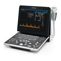
Mindray DP-50T Service Manual (183 pages)
Digital Ultrasonic Diagnostic Imaging System
Brand:
Mindray
| Category:
Diagnostic Equipment
| Size: 12 MB
Table of Contents
Table of Contents
3
Revision History
7
Intellectual Property Statement
8
Applicable for
8
Statement
9
Responsibility on the Manufacturer Party
9
Customer Service Department
9
Preface
11
Meaning of Signal Words
11
Meaning of Symbols
11
Meaning of Safety Symbols
11
Warning Labels
12
General Symbols
12
Safety Precautions
14
Electric Safety
14
Mechanical Safety
15
Personnel Safety
15
Other
15
Product Specifications
17
Overview
17
Intended Use
17
Introduction of each Unit
17
I/O Panel
19
Power Supply Panel
20
Control Panel
21
Peripherals Supported
24
Specifications
24
Dimensions and Weight
24
Electrical Specifications
24
Environmental Conditions
24
Monitor Specification
25
System Installation
27
Preparations for Installation
27
Electrical Requirements
27
Installation Condition
28
Unpacking
28
Unpacking
29
Checking
31
Installation of Main Unit
31
Installing Battery
31
Control Panel Adjusting
31
Display Adjusting
32
Installing Probe Holder
33
Connecting a Probe
33
Installing Peripherals
34
Footswitch Installation
34
Video Printer Installation
34
Installing a Graph / Text Printer
35
Installing Printer Adapter
35
Installing External DVD-R/W
40
System Configuration
40
Power on / off
40
Enter Doppler
40
System Preset
41
Print Preset
44
Network Preset
46
System Information
49
Hardware Principle
51
General Structure of Hardware System
51
Main Unit
52
Probe Board
52
Main Board
53
IO Broad
55
Drive Board (Optional)
56
Ultrasound System Monitor
56
Ultrasound System Indicator
57
Display
58
Control Panel
59
Power System
60
Power Output of the Power Supply Module and Supporting Function Distribution
60
System Power-On Control
61
Function and Performance Checking Method
65
Instruction
65
Checking System Status
65
System Running Status
65
General Exam
66
Check Flow
66
Checking Content
66
Function Checks
68
Check Flow
68
Checking Content
69
Performance Test
75
Test Process
75
Test Content
75
Software Upgrade and Maintenance
81
Enter the Maintenance Window
81
System Software Installation/ Restoration
82
Installation of Optional Devices
82
Data Backup and Storage
85
Manage Settings
85
Patient Data Backup and Restore
86
Software Maintenance
87
Product Configuration
87
Log Maintenance
87
Display Parameter Setting
89
HDD Partition
90
Field Replacement Unit
93
Explosive View
94
Assembly Explosive View
95
Monitor Assembly (A0)
95
Operation Panel Assembly (B0)
97
Core Assembly (C0)
99
Cable Set of Main Unit (D0)
104
台车(E0
105
Structure and Assembly/Disassembly
107
Structure of the Complete System
107
Preparations
107
Tools Required
107
Engineers Required
108
Assembly/Disassembly Required
108
Assembly/Disassembly
108
Battery Connecting Board
109
Power Supply Module
110
IO Broad
114
Probe Board
115
Main Board and CPU Module
115
Control Panel Assembly
117
Display Assembly
121
Hard Disk
122
Speaker
123
Printer Adapter (Optional)
125
System Diagnosis and Support
129
General Status Indicator
129
Status Indicators of the Control Panel
129
Status Indicator of the Power Supply on the IO Board
130
Status of Whole Machine
130
Starting Process of the Whole System
131
Start Process of Complete System
132
Start-Up Process of BIOS
133
Start-Up of Linux
133
Start-Up of Doppler
134
Alarming and Abnormal Information
136
Turning on the System Configuration File Is Abnormal
137
The Voltage of System Power Is Abnormal
137
Temperature Alarming
137
Fan Alarming
138
Battery Alarming
138
PHV Related Alarming
139
Care and Maintenance
141
Overview
141
Tools, Measurement Devices and Consumables
141
Care and Maintenance Items
142
Cleaning
143
Clean the System
143
Clean the Peripherals
146
Checking
146
General Check
146
System Function Check
147
Peripherals and Options Check
148
Mechanical Safety Inspection
148
Electrical Safety Inspection
149
Troubleshooting of Regular Malfunctions
151
System Cannot be Powered on
151
Module or Board Related
151
Key Points Supporting Troubleshooting
151
Troubleshooting
151
System Cannot Start up Normally
152
Module or Board Related
152
Key Points Supporting Troubleshooting
152
Troubleshooting
152
Image Fault
153
Module or Board Related
153
Key Points Supporting Troubleshooting
154
Troubleshooting
154
Probe Socket System Malfunction
155
Module or Board Related
155
Key Points Supporting Troubleshooting
155
Troubleshooting
155
IO Interface System
156
Module or Board Related
156
Key Points Supporting Troubleshooting
156
Troubleshooting
156
Control Panel
157
Module or Board Related
157
Key Points Supporting Troubleshooting
157
Troubleshooting
157
LCD Display
158
Module or Board Related
158
Key Points Supporting Troubleshooting
158
Troubleshooting
158
Printer Adapter Related Troubleshooting
160
Electrical Safety Inspection
163
Appendix B Phantom Usage Illustration
179
Advertisement
Advertisement
Related Products
Mindray DP-50
Mindray DP-50 PT
Mindray DP-50Expert
Mindray DP-50 Pro
Mindray DP-50S
Mindray DP-50W
Mindray DP-9900Plus
Mindray DP-Z6T
Mindray DP-Expert
Mindray DP-Z80
Mindray Categories
Medical Equipment
Diagnostic Equipment
Measuring Instruments
Monitor
Water Pump
More Mindray Manuals
Login
Sign In
OR
Sign in with Facebook
Sign in with Google
Upload manual
Upload from disk
Upload from URL