Sign In
Upload
Download
Table of Contents
Contents
Add to my manuals
Delete from my manuals
Share
URL of this page:
HTML Link:
Bookmark this page
Add
Manual will be automatically added to "My Manuals"
Print this page
×
Bookmark added
×
Added to my manuals
Manuals
Brands
IFM Electronic Manuals
Measuring Instruments
PG24 Series
Operating instructions manual
IFM Electronic PG24 Series Operating Instructions Manual
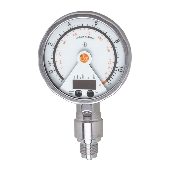
Electronic manometer
Hide thumbs
1
Table Of Contents
2
3
4
5
6
7
8
9
10
11
12
13
14
15
16
17
18
19
20
21
22
23
24
25
26
27
page
of
27
Go
/
27
Contents
Table of Contents
Bookmarks
Table of Contents
Table of Contents
Preliminary Note
Safety Instructions
Functions and Features
Function
4�1 Processing of the Measured Signals
4�2 Pressure Monitoring / Switching Function
4�3 Pressure Monitoring / Analogue Function
4�4 Customer-Specific Calibration
Installation
Electrical Connection
Operating and Display Elements
Menu
8�1 Menu Structure: Main Menu
8�2 Explanation of the Main Menu
8�3 Menu Structure: Level 2 (Extended Functions)
8�4 Explanation of the Menu Level 2
Parameter Setting
9�1 General Parameter Setting
9�2 Configuration of the Digital Display (Optional)
9�3 Set Output Signals
9�3�1 Set Output Functions
9�3�2 Set Switching Limits
9�3�3 Scale Analogue Value for OUT2
9�4 User Settings (Optional)
9�4�1 Carry out Zero Point Calibration
9�4�2 Set Delay Time for OUT1
9�4�3 Set Switching Logic for OUT1
9�4�4 Set Damping for the Switching Signal
9�4�5 Set Damping for the Analogue Signal
9�5 Service Functions
9�5�1 Read Min/Max Values for System Pressure
9�5�2 Reset All Parameters to Factory Setting
Operation
10�1 Read Set Parameters
10�2 Error Indications
Factory Setting
Advertisement
Quick Links
1
9�1 General Parameter Setting
Download this manual
Operating instructions
Electronic manometer
UK
PG24xx
Table of
Contents
Previous
Page
Next
Page
1
2
3
4
5
Advertisement
Table of Contents
Need help?
Do you have a question about the PG24 Series and is the answer not in the manual?
Ask a question
Questions and answers
Related Manuals for IFM Electronic PG24 Series
Measuring Instruments IFM Electronic PK5520 Installation Instructions
Electronic pressure monitor efector500 pk55xx (5 pages)
Measuring Instruments IFM Electronic Efector 500 Operating Instructions Manual
Electronic manometer (26 pages)
Measuring Instruments IFM Electronic PG2454 Operating Instructions Manual
Electronic manometer (27 pages)
Measuring Instruments IFM Electronic Efector 160 LK1222 Operating Instructions Manual
Electronic level sensor (75 pages)
Measuring Instruments IFM Electronic SI5006 Operating Instructions Manual
Flow monitors (14 pages)
Measuring Instruments IFM Electronic Efector 300 Operating Instructions Manual
Magnetic-inductive flow meter (31 pages)
Measuring Instruments IFM Electronic SM9000 Operating Instructions Manual
Magnetic-inductive flow meter (44 pages)
Measuring Instruments IFM Electronic Efector 300 SA3010 Operating Instructions Manual
Flow monitor (46 pages)
Measuring Instruments IFM Electronic efector300 SD6000 Operating Instructions Manual
Compressed air meter (60 pages)
Measuring Instruments IFM Electronic efector 300 Operating Instructions Manual
Compressed air meters (31 pages)
Measuring Instruments IFM Electronic Efector 300 SI1007 Operating Instructions Manual
Flow monitor (59 pages)
Measuring Instruments IFM Electronic SI5007 Operating Instructions Manual
Flow monitor (17 pages)
Measuring Instruments IFM Electronic efector300 SD2001 Operating Instructions Manual
Compressed air meter (23 pages)
Measuring Instruments IFM Electronic SD6050 Operating Instructions Manual
Compressed air meter (29 pages)
Measuring Instruments IFM Electronic efector300 SD6050 Operating Instructions Manual
Compressed air meter (26 pages)
Measuring Instruments IFM Electronic Efector 300 SI0556 Operating Instructions Manual
Flow monitors (15 pages)
This manual is also suitable for:
Pg2409
Pg2450
Pg2451
Pg2452
Pg2453
Pg2454
...
Show all
Pg2455
Pg2456
Pg2457
Pg2458
Pg2459
Table of Contents
Print
Rename the bookmark
Delete bookmark?
Delete from my manuals?
Login
Sign In
OR
Sign in with Facebook
Sign in with Google
Upload manual
Upload from disk
Upload from URL


Need help?
Do you have a question about the PG24 Series and is the answer not in the manual?
Questions and answers