Table of Contents
Advertisement
Advertisement
Table of Contents

Subscribe to Our Youtube Channel
Related Manuals for IFM Electronic SI5007


Summary of Contents for IFM Electronic SI5007
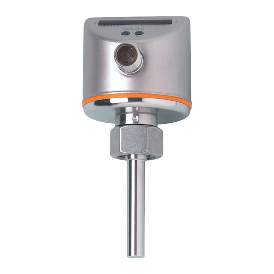
- Page 1 Operating instructions Flow monitor SI5007...
-
Page 2: Table Of Contents
Contents 1 Preliminary note ���������������������������������������������������������������������������������������������������3 1�1 Explanation of symbols ����������������������������������������������������������������������������������3 2 Safety instructions �����������������������������������������������������������������������������������������������4 3 Functions and features ����������������������������������������������������������������������������������������4 3�1 Applications ��������������������������������������������������������������������������������������������������4 3�2 Operating principle flow monitoring ���������������������������������������������������������������4 3�3 Operating principle temperature monitoring ��������������������������������������������������5 4 Installation������������������������������������������������������������������������������������������������������������6 4�1 Installation location ����������������������������������������������������������������������������������������6 4�2 Interference in the pipe system ���������������������������������������������������������������������7 4�3 Installation procedure ������������������������������������������������������������������������������������7 5 Electrical connection ��������������������������������������������������������������������������������������������8... -
Page 3: Preliminary Note
9 Troubleshooting �������������������������������������������������������������������������������������������������16 10 Maintenance ����������������������������������������������������������������������������������������������������17 11 Technical data ��������������������������������������������������������������������������������������������������17 1 Preliminary note 1.1 Explanation of symbols ► Instructions > Reaction, result → Cross-reference Important note Non-compliance can result in malfunction or interference� Information Supplementary note� LED lights green LED lights orange LED lights red LED flashes... -
Page 4: Safety Instructions
2 Safety instructions • Please read this document prior to set-up of the unit� Ensure that the product is suitable for your application without any restrictions� • If the operating instructions or the technical data are not adhered to, personal injury and/or damage to property can occur�... -
Page 5: 3�3 Operating Principle Temperature Monitoring
The hysteresis changes with the flow speed and it is essentially influenced by the set monitoring range� It is 2���5 cm/s for the setting 5���100 cm/s (= factory setting), it increases with higher flow speeds� • The typical response time of the unit is 1���10 s� It can be influenced by the switch point: - Low switch point = quick reaction with rising flow�... -
Page 6: Installation
4 Installation Using process adapters the unit can be adapted to different process connections� • Adapters have to be ordered separately as accessories� A correct fit of the unit and ingress resistance of the connection are only en- sured using ifm adapters� • For small flow rates ifm adapter blocks are available�... -
Page 7: 4�2 Interference In The Pipe System
4.2 Interference in the pipe system Components integrated in the pipes, bends, valves, reductions, etc� lead to turbu- lence of the medium� This affects the function of the unit� Recommendation: Adhere to the distances between sensor and sources of inter- ference: 5...10 x D 3...5 x D... -
Page 8: Electrical Connection
5 Electrical connection The unit must be connected by a qualified electrician� The national and international regulations for the installation of electrical equipment must be adhered to� Voltage supply according to EN 50178, SELV, PELV� ► Disconnect power� ► Connect the unit as follows: OUT2 OUT1 Pin 1... -
Page 9: Operating And Display Elements
6 Operating and display elements Flow High 0 1 2 3 4 5 6 7 8 [x10°C] Setpoint Flow Temp 1: Operation indication • The green LEDs indicate the current flow (LEDs 0 to 9 represent the range between flow standstill and maximum flow)� • A lit LED indicates the position of the switch point flow (SP1) (orange = output closed, red = output open)�... -
Page 10: 7�1�2 Device-Specific Information
7.1.2 Device-specific information You will find the IODDs necessary for the configuration of the IO-Link unit and detailed information about process data structure, diagnostic information and parameter addresses at www�ifm�com/gb/io-link� 7.1.3 Parameter setting tools You will find all necessary information about the required IO-Link hardware and software at www�ifm�com/gb/io-link�... -
Page 11: 7�3 Change Switch Point Sp1 For Flow (Optional)
Your normal flow is below the representation range of the display� Flow High 2 setting options: ► Change the switch point (→ 7.3). 0 1 2 3 4 5 6 7 8 [x10°C] ► Carry out high-flow adjustment (→ 7.4). Your normal flow exceeds the representation Flow High range of the display (LED 9 flashes)� ►... -
Page 12: 7�5 Set Switch Point Sp2 For Temperature
The unit is now adapted to your flow conditions� It returns to the operating mode, the display should now show example 1� The adjustment affects the switch point: it is increased proportionally (maxi- mum up to LED 7)� 7.5 Set switch point SP2 for temperature ►... -
Page 13: 7�6 Low-Flow Adjustment (Optional)
After LED 0 has been reached the cycle of the flashing LED starts again at LED 9; the continuously lit LED (tens digit) moves one position to the left (when setting is made with )� 0 1 2 3 4 5 6 7 8 [x10°C] 0 1 2 3 4 5 6 7 8 [x10°C]... -
Page 14: 7�8 Restore The Factory Setting (Reset)
Using an IO-Link capable parameter setting tool, the outputs can be sepa- rately set as normally closed or normally open� 7.8 Restore the factory setting (reset) ► Press for at least 15 s� > LED 9 lights, after approx� 5 s it flashes� >... -
Page 15: Operation
8 Operation After every power on all LEDs light and go out again step by step (during this time the outputs are closed if configured as normally open)� The unit is then ready for operation� In case of power failure or interruption all settings remain� 8.1 Display current temperature and switch point SP2 ►... -
Page 16: 8�3 Interference Indicators
8.3 Interference indicators Short circuit at switching output OUT1� The operating indicator and 5 red LEDs on the left light alternately� 0 1 2 3 4 5 6 7 8 [x10°C] If the short circuit has been rectified, the unit imme- 0 1 2 3 4 5 6 7 8 [x10°C] diately passes into the normal operating state�... -
Page 17: Technical Data
10 Maintenance Recommended maintenance: ► Check the sensor tip for build-up from time to time� ► Clean it using a soft cloth� Stubborn build-up (e�g� lime) can be removed using a common vinegar cleaning agent� 11 Technical data Technical data and scale drawing at www�ifm�com� More information at www�ifm�com...
Need help?
Do you have a question about the SI5007 and is the answer not in the manual?
Questions and answers