IFM Electronic Efector 500 Operating Instructions Manual
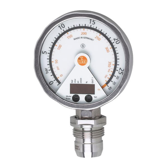
Electronic manometer
Hide thumbs
Also See for Efector 500:
- Operating instructions manual (38 pages) ,
- Operating instructions manual (55 pages)
Table of Contents
Advertisement
Advertisement
Table of Contents

Related Manuals for IFM Electronic Efector 500


Summary of Contents for IFM Electronic Efector 500
- Page 1 Operating instructions Electronic manometer PG28xx...
-
Page 2: Table Of Contents
Contents 1 Preliminary note ���������������������������������������������������������������������������������������������������3 1�1 Symbols used ������������������������������������������������������������������������������������������������3 2 Safety instructions �����������������������������������������������������������������������������������������������4 3 Functions and features ����������������������������������������������������������������������������������������4 3�1 Applications ���������������������������������������������������������������������������������������������������4 4 Function ���������������������������������������������������������������������������������������������������������������5 4�1 Processing of the measured signals ��������������������������������������������������������������5 4�2 Pressure monitoring / switching function �������������������������������������������������������5 4�3 Pressure monitoring / analogue function �������������������������������������������������������6 4�4 Customer-specific calibration ������������������������������������������������������������������������7 5 Installation������������������������������������������������������������������������������������������������������������8 6 Electrical connection ��������������������������������������������������������������������������������������������9... -
Page 3: Preliminary Note
9�5 Service functions �����������������������������������������������������������������������������������������21 9�5�1 Read min/max values for system pressure ����������������������������������������21 9�5�2 Reset all parameters to factory setting �����������������������������������������������21 10 Operation ���������������������������������������������������������������������������������������������������������21 10�1 Read set parameters ���������������������������������������������������������������������������������21 10�2 Error indications �����������������������������������������������������������������������������������������21 11 Scale drawing �������������������������������������������������������������������������������������������������22 12 Technical data ��������������������������������������������������������������������������������������������������23 13 Setting ranges��������������������������������������������������������������������������������������������������25 14 Factory setting �������������������������������������������������������������������������������������������������26 1 ... -
Page 4: Safety Instructions
2 Safety instructions • Please read this document prior to set-up of the unit. Ensure that the product is suitable for your application without any restrictions. • If the operating instructions or the technical data are not adhered to, personal injury and/or damage to property can occur. -
Page 5: Function
Avoid static and dynamic overpressure exceeding the given overload pres- sure by taking appropriate measures. The indicated bursting pressure must not be exceeded. Even if the bursting pressure is exceeded only for a short time, the unit may be destroyed. ATTENTION: risk of injury! Use in gases at pressures >... -
Page 6: 4�3 Pressure Monitoring / Analogue Function
P = system pressure; HY = hysteresis; FE = window 4.3 Pressure monitoring / analogue function The analogue output can be configured: [OU2] defines whether the set measuring range is provided as 4���20 mA ([OU2] = [I]) or as 20���4 mA ([OU2] = [InEG])� Scaling can be set by means of the teaching process or by entering a value for the ASP and AEP parameters�... -
Page 7: 4�4 Customer-Specific Calibration
In the set measuring range the output signal is between 4 and 20 mA ([OU2] = [I]) or between 20 and 4 mA ([OU2] = [InEG])� It is also indicated: • System pressure above the measuring range: - Output signal 20 to 20�5 mA at [OU2] = [I]� - Output signal 4 to 3�8 mA at [OU2] = [InEG]�... -
Page 8: Installation
• P = measured pressure; P‘ = modified measured value CP2' • CP1 = calibration point 1; CP2 = calibration point 2; CP2‘ = modified measured value for • 1 = curve of measured values at factory setting • 2 = curve of measured values after calibration •... -
Page 9: Electrical Connection
Use in hygienic areas to EHEDG ► Make sure that the sensors are integrated into the system in accordance with EHEDG� After installation the analogue display can be rotated / adapted to the instal- lation position� Use gloves to do so� 6 Electrical connection The unit must be connected by a qualified electrician� The national and international regulations for the installation of electrical equipment must be adhered to�... -
Page 10: Operating And Display Elements
7 Operating and display elements Mode/ Enter 1: Analogue display - Display of the current system pressure in bar and PSI or mbar and inH2O� 2: LED ring - Display of set point and reset point� - Trend display: rising pressure (5 LEDs below the pointer) / falling pressure (5 LEDs above the pointer)�... -
Page 11: Menu
6: Touch button Mode/Enter* - Selection of the parameters and acknowledgement of the parameter values� * The two touch buttons are activated simply by touching / deactivated by releasing the touch button� The touch button must be completely covered to be activated� Slow covering (e�g� liquid flows over the display) does not activate the touch button� 8 ... -
Page 12: 8�2 Explanation Of The Main Menu
8.2 Explanation of the main menu SP1/rP1 Upper / lower limit value for system pressure at which OUT1 switches� Output function for OUT1: • Switching signal for the pressure limit values: hysteresis function [H ��] or window function [F ��], either normally open [� no] or normally closed [� nc]� Output function for OUT2: •... -
Page 13: 8�3 Menu Structure: Level 2 (Extended Functions)
8.3 Menu structure: level 2 (extended functions) 1: Change to the main menu... -
Page 14: 8�4 Explanation Of The Menu Level 2
8.4 Explanation of the menu level 2 Standard unit of measurement for system pressure� Display mode: SELd • Pressure in the unit set in [Uni]� • Pressure in % of the set scaling of the analogue output� Analogue start point for system pressure: measured value at which 4 mA is provided (20 mA if [OU2] = [InEG])�... -
Page 15: Parameter Setting
9 Parameter setting During parameter setting the unit remains in the operating mode� It continues its monitoring function with the existing parameters until the parameter setting has been completed� 9.1 General parameter setting 3 steps must be taken for each parameter setting: Select parameter ►... - Page 16 Mode/ Enter the valid code no� appears� ► Touch [Mode/Enter] briefly� On delivery by ifm electronic: no access restriction� • Locking / unlocking The unit can be locked electronically to prevent an unintentional operation� ► Make sure that the unit is in the normal operating mode�...
-
Page 17: 9�2 Configuration Of The Digital Display (Optional)
9.2 Configuration of the digital display (optional) ► Select [Uni] and set the unit of measurement: - [bAr], [mbAr], [PSI], [inHO]� ► Select [SELd] and set type of indication: - [P]: system pressure in the unit set in Uni� - [P%]: system pressure in % of the set scaling of the analogue output; the following applies: 0% = ASP value / 100% = AEP value�... -
Page 18: 9�3 Set Output Signals
9.3 Set output signals 9.3.1 Set output functions ► Select [OU1] and set the switching function: - [Hno] = hysteresis function/NO� - [Hnc] = hysteresis function/NC� - [Fno] = window function/NO� - [Fnc] = window function/NC� ► Select [OU2 ] and set the analogue function: - [I] = current signal proportional to pressure 4…20 mA�... -
Page 19: 9�4 User Settings (Optional)
As an alternative: ► Select [ASP] and set the measured value at which 4 mA is provided (20 mA at [OU2] = [InEG])� ► Select [AEP] and set the measured value at which 20 mA is provided (4 mA at [OU2] = [InEG])� Minimum distance between ASP and AEP = 25 % of the final value of the measuring range (turn-down 1:4)�... -
Page 20: 9�4�5 Set Damping For The Analogue Signal
9.4.5 Set damping for the analogue signal ► Select [dAA] and set a value between 0�01 and 30 s� dAA value = response time between pressure change and change of the analogue signal in seconds� 9.4.6 Calibrate curve of measured values If the unit is to adopt the settings for the calibration points, the following conditions must be adhered to: - CP1 and CP2 must be within the measuring range (i�e�... -
Page 21: 9�5 Service Functions
9.5 Service functions 9.5.1 Read min/max values for system pressure ► Select [HI] or [LO] and touch [Set] briefly� [HI] = maximum value, [LO] = minimum value� Delete memory: ► Select [HI] or [LO]� ► Touch [Set] and keep it touched until [----] is displayed� ► Touch [Mode/Enter] briefly� 9.5.2 ... -
Page 22: Scale Drawing
11 Scale drawing Dimensions in mm 1: analogue display 2: digital display 3: touch button (programming button) -
Page 23: Technical Data
12 Technical data Operating voltage [V] ������������������������������������������������������������������������������������������� 18���32 DC Current consumption [mA] ���������������������������������������������������������������������������������� < 70 (24 V) Current rating [mA] ��������������������������������������������������������������������������������������������������������� 250 Short-circuit protection; reverse polarity protection / overload protection, integrated watchdog Voltage drop [V] �������������������������������������������������������������������������������������������������������������� < 2 Power-on delay time [s] ����������������������������������������������������������������������������������������������������� 6 Min�... - Page 24 Materials (wetted parts) �������������������������������� stainless steel 316L / 1�4435, surface characteristics: Ra < 0�4 / Rz 4 ceramics (99�9 % Al2O3); PTFE Housing materials ���������������������������� stainless steel 316L / 1�4404; PA; FPM (Viton); PTFE; viewing glass: laminated safety glass 4 mm Protection rating ��������������������������������������������������������������������������������������������IP 67 / IP 69K Protection class ������������������������������������������������������������������������������������������������������������������III Insulation resistance [MΩ] �������������������������������������������������������������������������>...
-
Page 25: Setting Ranges
13 Setting ranges ΔP mbar -4�8 160�0 -5�0 159�8 -5�0 135�0 20�0 160�0 0�1 inH2O -1�95 64�25 -2�05 64�15 -2�00 54�20 8�05 64�25 0�05 -0�96 40�00 -1�00 39�96 -1�00 33�76 5�24 40�00 0�02 -13�8 579�9 -14�4 579�3 -14�4 489�3 75�9 579�9 0�3 -0�98 16�00... -
Page 26: Factory Setting
14 Factory setting Factory setting User setting 25.0 % VMR* 24.9 % VMR* COF / tCOF ASP / tASP 0% VMR* AEP / tAEP 100% VMR* bAr / mbAr SELd 0.06 0.03 SPRP 0.00 0.00 * = the indicated percentage of the final value of the measuring range (VMR) of the cor- responding sensor is set� More information at www�ifm�com...
Need help?
Do you have a question about the Efector 500 and is the answer not in the manual?
Questions and answers