
Related Manuals for IFM Electronic SM9000


Summary of Contents for IFM Electronic SM9000
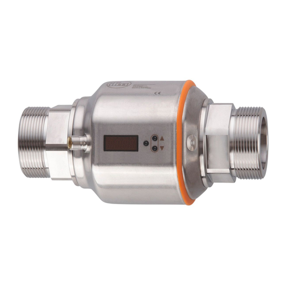
- Page 1 Operating instructions Magnetic-inductive flow meter SM9000 SM9100 SM2000 SM2100...
-
Page 2: Table Of Contents
Contents 1 Preliminary note ���������������������������������������������������������������������������������������������������4 1�1 Symbols used ������������������������������������������������������������������������������������������������4 1�2 Warning signs used ���������������������������������������������������������������������������������������5 2 Safety instructions �����������������������������������������������������������������������������������������������5 3 Functions and features ����������������������������������������������������������������������������������������6 4 Function ���������������������������������������������������������������������������������������������������������������6 4�1 Measuring principle for volumetric flow monitoring ����������������������������������������6 4�2 Processing of the measured signals ��������������������������������������������������������������7 4�3 Volumetric flow monitoring �����������������������������������������������������������������������������7 4�3�1 Volumetric flow quantity ������������������������������������������������������������������������7 4�3�2 Direction of flow ������������������������������������������������������������������������������������7... - Page 3 8 Menu �����������������������������������������������������������������������������������������������������������������23 8�1 Process value display ����������������������������������������������������������������������������������23 8�2 Main menu ���������������������������������������������������������������������������������������������������24 8�2�1 Explanation main menu ����������������������������������������������������������������������25 8�3 Extended functions – Basic settings ������������������������������������������������������������26 8�3�1 Explanation extended functions (EF) ��������������������������������������������������27 8�3�2 Submenu basic settings (CFG) ����������������������������������������������������������27 8�4 Extended functions – Min/max memory – Emtpy pipe – Simulation ������������28 8�4�1 Explanation extended functions (EF) ��������������������������������������������������29 8�4�2 Submenu min/max memory (MEM) ����������������������������������������������������29 8�4�3 Submenu empty pipe (EPD) ���������������������������������������������������������������29...
-
Page 4: Preliminary Note
10�6�1 Setting of the standard unit of measurement for volumetric flow ������35 10�6�2 Configuration of the standard display �����������������������������������������������36 10�6�3 Changing the direction of the flow rate measurement ����������������������36 10�6�4 Setting the output logic ���������������������������������������������������������������������36 10�6�5 Setting the start-up delay ������������������������������������������������������������������36 10�6�6 Setting the measured value damping �����������������������������������������������36 10�6�7 Setting the error behaviour of the outputs ����������������������������������������37 10�6�8 Configuring the empty pipe detection as diagnostic output ��������������37... -
Page 5: 1�2 Warning Signs Used
1.2 Warning signs used CAUTION Warning of personal injury� Slight reversible injuries may result� 2 Safety instructions • Please read this document prior to set-up of the unit� Ensure that the product is suitable for your application without any restrictions� • Improper or non-intended use may lead to malfunctions of the unit or to un- wanted effects in your application�... -
Page 6: Functions And Features
3 Functions and features Pressure Equipment Directive (PED): The units comply with section 3, article (3) of the Directive 97/23/EC and must be designed and manufactured for non-super- heated liquids of group 1 fluids in accordance with the sound engineering practice� The unit monitors liquid media�... -
Page 7: 4�2 Processing Of The Measured Signals
Both electrodes must be wetted by the medium� Otherwise the signal [SEnS] for empty pipe is provided, if empty pipe detection is enabled� 4.2 Processing of the measured signals The unit displays the current process values� It generates 2 output signals according to the parameter setting� OUT1/IO-Link: 5 selection options Parameter setting - Switching signal for volumetric flow limit values... -
Page 8: 4�4 Consumed Quantity Monitoring (Totaliser Function)
► Use the supplied label to mark the changed flow direction� Direction of flow in accordance with "flow direction" > process value and display positive� Direction of flow against the “flow direction” > process value and display negative� Only positive process values are processed for the signal output (limit values and analogue values for volumetric flow)�... -
Page 9: 4�4�1 Consumed Quantity Monitoring With Pulse Output
- The meter saves the totalled consumed quantity every 10 minutes� In the event of a power failure this value is retained as the current meter reading� If a time-controlled reset is set, the elapsed time of the set reset interval is also stored�... -
Page 10: 4�7 Volumetric Flow Or Temperature Monitoring / Switching Function
> The flow is set to zero� The empty pipe detection can be set as time-depending or not time depending (→ 10�6�10)� 4.7 Volumetric flow or temperature monitoring / switching function OUTx changes its switching state if it is above or below the set switching limits (SPx, rPx)� The following switching functions can be selected:... -
Page 11: 4�7�1 Hysteresis Function
4.7.1 Hysteresis function Normally open: [OUx] = [Hno] Normally closed: [OUx] = [Hnc] First the set point (SPx) is set, then the reset point (rPx) with the requested difference� Example of volumetric flow monitoring HY = hysteresis 4.7.2 Window function Normally open: [OUx] = [Fno] Normally closed: [OUx] = [Fnc] The width of the window can be set by... -
Page 12: 4�8 Volumetric Flow Or Temperature Monitoring / Analogue Function
4.8 Volumetric flow or temperature monitoring / analogue func- tion 4.8.1 Current output [mA] -130 -120 [°C] Characteristics of the analogue output according to the standard IEC 60947-5-7 1: Output current 2: Volumetric flow quantity 3: Temperature 4: Display range 5: Measuring range 6: Range between analogue start point and analogue end point 7: The unit is in the error state (FOU = OFF)�... -
Page 13: 4�8�2 Voltage Output
4.8.2 Voltage output [ V ] 12,0 11,5 10,0 [°C] Characteristics of the analogue output according to the standard IEC 60947-5-7 1: Output voltage 2: Volumetric flow quantity 3: Temperature 4: Display range 5: Measuring range 6: Range between analogue start point and analogue end point 7: The unit is in the error state (FOU = OFF) or the process value transmitted in an ana- logue way is below the display range�... -
Page 14: 4�9 Volumetric Flow Monitoring / Frequency Output
4.9 Volumetric flow monitoring / frequency output FrEP Output curve frequency output 1: Frequency output 2: Volumetric flow quantity Q 3: The unit is in the error state (FOU = OFF) or the process value transmitted in an ana- logue way is below the display range� 4: The unit is in the error state (FOU = ON)�... - Page 15 After the start of the start-up delay there are 3 options: 1� The volumetric flow increases quickly and reaches the set point / good range within dST� > Outputs remain active� 2� The volumetric flow increases slowly and does not reach the set point /good range within dST�...
-
Page 16: 4�11 Low Flow Cut-Off (Lfc)
Example: dST for window function 0,5% 1 Volumetric flow quantity Q reaches 0�5 % of VMR > dST starts, output becomes active� 2 dST elapsed, Q reached good range > output remains active� 3 Q above SP (leaves good range) > output is reset� 4 Q again below SP >... -
Page 17: Installation
5 Installation ► Avoid deposits, accumulated gas and air in the pipe system� 5.1 Recommended installation locations Example of an optimised installation: ► Install the unit so that the measuring pipe is completely filled� ► Arrange for inlet and outlet pipe lengths� Disturbances caused by bends, valves, reductions, etc�... - Page 18 ► Install in front of or in a rising pipe: F = flow direction With empty pipe detection: ► Install the unit according to figure 1, 4 or 5�...
-
Page 19: 5�2 Installation Locations To Be Avoided
5.2 Installation locations to be avoided • Directly in front of a falling pipe� • In a falling pipe� • On the suction side of a pump� • Directly in front of the spout of the pipe� • At the highest point of the pipe system� F = flow direction The unit can be installed independently of the orientation if the following is ensured:... -
Page 20: 5�3 Grounding
5.3 Grounding If installed in an ungrounded pipe system (e�g� plastic pipes), the unit must be grounded (functional earth)� Ground brackets for the M12 connector are available as accessories (→ www.ifm. com)� 5.4 Installation in pipes The unit can be installed in pipes using adapters� The adapters have to be ordered separately as accessories (→ www.ifm.com). -
Page 21: Electrical Connection
6 Electrical connection The unit must be connected by a qualified electrician� The national and international regulations for the installation of electrical equipment must be adhered to� Voltage supply according to EN 50178, SELV, PELV� ► Disconnect power� ► Connect the unit as follows: OUT2/InD OUT1/IO-Link Pin 1... -
Page 22: Operating And Display Elements
7 Operating and display elements ▲ Enter ▼ 1 to 8: Indicator LEDs • LEDs 1-6 = Unit of the currently represented numerical value → 11.1 Reading the process value • LED 7 = switching state of output OUT2 / of input InD • LED 8 = switching status of output OUT1 9: Alphanumeric display, 4 digits • Current volumetric flow quantity (with setting [SELd] = [FLOW]) • Meter reading of the totaliser (with setting [SELd] = [TOTL]) • Current medium temperature (with setting [SELd] = [TEMP]) -
Page 23: Menu
8 Menu 8.1 Process value display l/min °C * Stored totaliser value ↓ Main menu... -
Page 24: 8�2 Main Menu
8.2 Main menu ↑ Process value display ↓ Extended functions * The parameters are only displayed when selected at OU1� ** The parameters are only displayed when selected at OU2�... -
Page 25: 8�2�1 Explanation Main Menu
8.2.1 Explanation main menu Maximum limit value for the set process value Minimum limit value for the set process value ImPS Pulse value ImPR Pulse reset Frequency output of the end point of the flow value FrEP Frequency output of the end point of the frequency Output function for OUT1 (volumetric flow or consumed quantity) Output function for OUT2 (volumetric flow or temperature) As an alternative: configure OUT2 (Pin2) as input for external reset signal:... -
Page 26: 8�3 Extended Functions - Basic Settings
8.3 Extended functions – Basic settings ↑ Main menu * The parameters are only displayed when selected at OU1� ** The parameters are only displayed when selected at OU2�... -
Page 27: 8�3�1 Explanation Extended Functions
8.3.1 Explanation extended functions (EF) Restore the factory setting Counter reset: manual reset / time-controlled reset Submenu basic settings Submenu min/max memory Submenu empty pipe Submenu simulation 8.3.2 Submenu basic settings (CFG) FOU1 Behaviour of output 1 in case of an error FOU2 Behaviour of output 2 in case of an error Start-up delay of volumetric flow monitoring... -
Page 28: 8�4 Extended Functions - Min/Max Memory - Emtpy Pipe - Simulation
8.4 Extended functions – Min/max memory – Emtpy pipe – Simulation ↑ Main menu * Parameters are only displayed for the selection EP�On = On�... -
Page 29: 8�4�1 Explanation Extended Functions
8.4.1 Explanation extended functions (EF) Restore the factory setting Counter reset: manual reset / time-controlled reset Submenu basic settings Submenu min/max memory Submenu empty pipe Submenu simulation 8.4.2 Submenu min/max memory (MEM) HI�F Max� value flow LO�F Min� value flow HI�T Max�... -
Page 30: Set
9 Set-up After power on and expiry of the power-on delay time (approx� 5 seconds) the unit is in the normal operating mode� It carries out its measurement and evaluation functions and generates output signals according to the set parameters� • During the power-on delay time the outputs are switched as programmed: - ON with normally open function (Hno / Fno) - OFF with normally closed function (Hnc / Fnc)�... -
Page 31: 10�2 Changing The Parameter Value
10.2 Changing the parameter value Select the parameter 1� Press [Enter] briefly� 2� Press [▲] or [▼] until the requested parameter is displayed. Changing the parameter value 3� Press [Enter] briefly� > The currently set value is displayed� 4� Keep [▲] or [▼] pressed for 1 s > Display flashes first, then permanent� 5�... -
Page 32: 10�2�1 Switching Between The Menu Levels
10.2.1 Switching between the menu levels Change to the Switching to the next submenu via the parameters [EF], [CFG], submenu [MEM], [EPD] or [SIM]� ► Select a submenu with [▲] or [▼] and switch to the submenu by pressing [Enter]� Back to the process ► Wait for 30 seconds value display ►... -
Page 33: 10�2�4 Setting The Pulse Value
10.2.4 Setting the pulse value ► Select [ImPS]� ► Press [▲] or [▼], until the requested power of ten is displayed; confirm with [Enter]� The power of ten is signalled by the decimal point and the unit by the corresponding indicator LED (→ 7). ► Press [▲] or [▼], until the requested numerical value is displayed; confirm with [Enter]� Keep [▲] or [▼] pressed. > Accelerated cycle of the values� 10.3 Settings for consumed quantity monitoring 10.3.1 Settings for limit value monitoring with OUT1 ►... -
Page 34: 10�3�4 Setting The Frequency Value For Volumetric Flow
10.3.4 Setting the frequency value for volumetric flow ► Select [OU1] and set [FRQ]� ► Select [FEP] and set the flow value at which the frequency set in FrEP is provided� ► Select [FrEP] and set the frequency� 10.4 Settings for consumed quantity monitoring 10.4.1 Settings for quantity monitoring via pulse output ►... -
Page 35: 10�4�6 Configure Counter Reset Using An External Signal
10.4.6 Configure counter reset using an external signal ► Select [OU2] and set [InD]� ► Select [Din2] and set the reset signal: - [HIGH] = reset for high signal, - [LOW] = reset for low signal, - [+EDG] = reset for rising edge, - [-EDG] = reset for falling edge�... -
Page 36: 10�6�2 Configuration Of The Standard Display
10.6.2 Configuration of the standard display ► Select [SELd] and determine the standard measuring unit: - [FLOW] = the current volumetric flow value in the standard unit of measurement is displayed� - [TOTL] = display indicates the current meter count in l, m or 1000 m �... -
Page 37: 10�6�7 Setting The Error Behaviour Of The Outputs
10.6.7 Setting the error behaviour of the outputs ► Select [FOU1] and set the value: 1� Switching output: - [On] = output 1 switches ON in case of an error� - [OFF] = output 1 switches OFF in case of an error� - [OU1] = output 1 switches irrespective of the error as defined with the parameters�... -
Page 38: 10�6�11 Setting The Counting Method Of The Totaliser
10.6.11 Setting the counting method of the totaliser ► Select [FPro] and set the value: [-+] = totalling the volumetric flow values with the correct sign� [0+] = totalling only positive volumetric flow values� 10.6.12 Setting the low flow cut-off ►... -
Page 39: 10�7�3 Simulation Menu
10.7.3 Simulation menu ► Select [S�FLW] and set the flow value to be simulated� ► Select [S�TMP] and set the temperature value to be simulated� ► Select [S�Tim] and set the time of the simulation in minutes� ► Select [S�On] and set the function: - [On]: The simulation starts�... -
Page 40: Operation
11 Operation 11.1 Reading the process value The LEDs 1-6 signal which process value is currently displayed�The process value to be displayed as standard (temperature, flow velocity or meter reading of the totaliser) can be preset → 10.6.2 Configuration of the standard display. A standard unit of measurement can be defined for the flow velocity (l/min or m /h → 10.6.1). -
Page 41: 11�2 Reading The Parameter Value
11.2 Reading the parameter value To display the currently set parameter value, take the following steps: Select the parameter 1� Press [Enter] briefly� 2� Press [▲] or [▼] until the requested parameter is displayed. Display the parameter value 3� Press [Enter] briefly� > The currently set value is displayed for 30 s�... -
Page 42: 11�3 Error Indications
11.3 Error indications Warning message [SC1] Short circuit in OUT1� LED8 for OUT1 flashes (→ 7 Operating and display elements). [SC2] Short circuit in OUT2� LED7 for OUT2 flashes (→ 7 Operating and display elements). [SC] Short circuit in both outputs� LED7 and LED8 flash (→ 7 Operating and display elements). [OL] Detection zone of volumetric flow or temperature exceeded� [UL] Below the detection zone of volumetric flow or temperature� [Err] • Unit faulty / malfunction�... -
Page 43: Factory Setting
13 Factory setting Factory setting User setting 20 % * 19.5 % * ImPS ImPR SP2 (FLOW) 40 % * rP2 (FLOW) 39.5 % * SP2 (TEMP) 20 °C rP2 (TEMP) -19.6 °C ASP (FLOW) 0 % * AEP (FLOW) 100 % * ASP (TEMP) -20 °C... - Page 44 Lmin SELd FLOW SEL2 FLOW EP.On dEP.E dEP.F S.FLW 20 % S.TMP 20 °C S.Tim 2 min * of VMR More information at www�ifm�com...
Need help?
Do you have a question about the SM9000 and is the answer not in the manual?
Questions and answers