Table of Contents
Advertisement
Advertisement
Table of Contents

Related Manuals for IFM Electronic ecomot200 FR-2


Summary of Contents for IFM Electronic ecomot200 FR-2
- Page 1 Operating instructions Monitor FR-2 / FR-2N...
-
Page 2: Table Of Contents
Contents 1 Preliminary note ���������������������������������������������������������������������������������������������������4 1�1 Symbols used ������������������������������������������������������������������������������������������������4 1�2 Warning signs used ���������������������������������������������������������������������������������������4 2 Safety instructions �����������������������������������������������������������������������������������������������5 2�1 General ����������������������������������������������������������������������������������������������������������5 2�2 Target group ���������������������������������������������������������������������������������������������������5 2�3 Electrical connection ��������������������������������������������������������������������������������������5 2�4 Operation �������������������������������������������������������������������������������������������������������5 2�5 Location ���������������������������������������������������������������������������������������������������������6 2�6 Housing temperature �������������������������������������������������������������������������������������6 2�7 Tampering with the device �����������������������������������������������������������������������������6 3 Functions and features ����������������������������������������������������������������������������������������6 4 Operating and display elements ��������������������������������������������������������������������������8 4�1 Display stand-by mode ����������������������������������������������������������������������������������9... - Page 3 7 Navigation and parameter overview ������������������������������������������������������������������14 7�1 System parameters��������������������������������������������������������������������������������������15 7�1�1 FOx �����������������������������������������������������������������������������������������������������15 7�1�2 SOx �����������������������������������������������������������������������������������������������������15 7�1�3 FWx ����������������������������������������������������������������������������������������������������16 7�1�4 NCx �����������������������������������������������������������������������������������������������������16 7�1�5 DIM �����������������������������������������������������������������������������������������������������16 7�1�6 VER ����������������������������������������������������������������������������������������������������17 7�2 Application parameters ��������������������������������������������������������������������������������17 7�2�1 SPx �����������������������������������������������������������������������������������������������������17 7�2�2 HYx �����������������������������������������������������������������������������������������������������17 7�2�3 STx �����������������������������������������������������������������������������������������������������17 7�2�4 DTx �����������������������������������������������������������������������������������������������������18 7�2�5 FTx �����������������������������������������������������������������������������������������������������18 8 Programming �����������������������������������������������������������������������������������������������������19...
-
Page 4: Preliminary Note
1 Preliminary note This document is part of the device and contains information about the correct handling of the product� This document is intended for specialists� These specialists are people who are qualified by their training and their experience to see risks and to avoid possible hazards that may be caused during operation or maintenance of the device�... -
Page 5: Safety Instructions
2 Safety instructions 2.1 General Follow the operating instructions� Non-observance of the instructions, operation which is not in accordance with use as prescribed below, wrong installation or incorrect handling can affect the safety of operators and machinery� The installation and connection must comply with the applicable national and international standards�... -
Page 6: 2�5 Location
The design of the unit corresponds to the protection class II except for the terminal blocks� Protection against accidental contact (finger protection to IP 20) for qualified personnel is only guaranteed if the terminal screw has been completely screwed in� 2.5 Location For the correct operation the unit must be mounted in a housing (protection rating IP 40 or higher) which can only be opened using a tool or in a locked control... - Page 7 In 1 In 2 MONITOR FR-2 Out 1 Out 2 Example: Rotational speed monitoring of 2 electric motors 1: Pulse pick-ups on the motor shafts 2: Switching cam 3: Electric motors 4: Switching outputs 5: Signals depending on the selected switching functions WARNING The device is not approved for safety-related tasks in the field of operator protection�...
-
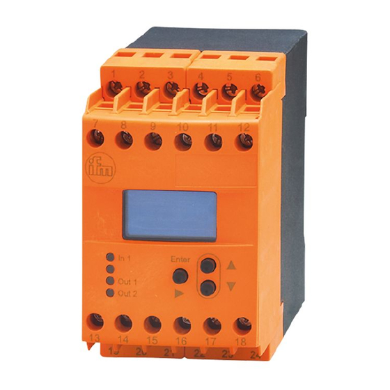
Page 8: Operating And Display Elements
4 Operating and display elements CH1 CH2 CH3 RUN PRG KEY 0.0.0.0.0 F...-xN (NAMUR) Enter Out1 Out2 OLED display Indicators for input channels and operating modes CH... Input channels Run mode (normal operating mode) Test mode (check of the switching characteristics without pulse pick-up connected) Programming mode (setting of the parameter values) Locking... -
Page 9: 4�1 Display Stand-By Mode
[▲] and [▼] buttons Selection of the actual value display, parameter selection, setting of the parameter values [Enter/►] button Selection of the operating mode, acknowledgement of the parameter value, front reset LEDs In1/2 (yellow) Input pulses LEDs Out1/2 (green) Switching status of the outputs 1 and 2 Output is not switched�... -
Page 10: 5�2 Installation Of The Sensors
5.2 Installation of the sensors ► Follow the manufacturer’s installation instructions� 6 Electrical connection 6.1 Terminal connection Monitor FR-2 Monitor FR-2N Power Power AC or DC Sensor Sensor supply supply I<0,1mA In 1 I>6,0mA Out 1 Out 1 In 1 Sensor supply In 2... -
Page 11: 6�2�2 Dc Supply
6.2.2 DC supply ► The SELV criteria (safety extra-low voltage) must be met for the DC supply� ► The DC supply cable L+ (terminal 2) must be protected externally with a 315 mA T fuse (5 x 20 mm or similar)� The DC supply terminals are directly connected to the sensor supply terminals�... -
Page 12: 6�3�3 Typical Input Circuit F
A +24 V DC continuous signal leads to a permanent bridging of the monitoring, i�e� the same state as during the start-up delay is indicated� When the voltage is no longer applied and the set start-up delay has elapsed, monitoring starts� Note on F���-xN: The +24 V DC signal voltage required for the reset inputs is not available to the F���-xN�... -
Page 13: 6�4 Outputs
6.4 Outputs 6.4.1 Relay outputs (Out1, 2 ) ► To prevent excessive wear and to comply with the EMC standards, interference suppression of the contacts is required for switching inductive loads� WARNING If the device is operated on an AC supply (terminals 7/8) this must use the same supply cable as the voltage supply to switch an AC voltage via the relay outputs�... -
Page 14: Navigation And Parameter Overview
7 Navigation and parameter overview The pushbuttons [▲] / [▼] and [Enter/►] are used for the navigation, entry of values and acknowledgement within the parameters arranged in columns� RUN mode Parameter range and PRG mode FW1* FW2* Input 1 [RPM/Hz] Input 2 [RPM/Hz] 1: Display: actual value input 1... -
Page 15: 7�1 System Parameters
7.1 System parameters 7.1.1 FOx Function Output (switching function of the outputs 1/2) Relay energised (transistor output switched) when the current value is below the switch point SPx (signalled state: "minimum speed"/"blocked")� Relay de-energised (transistor output blocked) when the current value is below the switch point SPx (error message: "underspeed "/"blocked")�... -
Page 16: 7�1�3 Fwx
7.1.3 FWx Function Wire Break Monitoring (only F���-xN) Relay characteristics for wire fault or short circuit, i�e� input frequency = 0 Frequency > SPx FWx = inactive (0) FWx = active (1) FOx = 1 or 4 relay energised relay de-energised FOx = 2 or 3 relay de-energised relay remains de-energised... -
Page 17: 7�1�6 Ver
7.1.6 VER Software version The installed software version is displayed (5-digit number with abbreviation VCO)� 7.2 Application parameters 7.2.1 SPx Switch Point (outputs 1/2) Value at which the output 1/2 changes its switching state according to switching function FOx� Values 0�1 ���... -
Page 18: 7�2�4 Dtx
7.2.4 DTx Delay Time (for outputs 1/2) Enables a delayed switching of the outputs 1/2� The respective output switches only if the current value is above or below the switch point for more than the time set here� Values 0�0���1000�0 s Default value 0�0 (no delay time) 7.2.5 FTx... -
Page 19: Programming
8 Programming WARNING If programming takes place during operation, dangerous contact voltage may occur� Therefore ensure that programming is done by a qualified electrician� Parameter changes during operation, especially changes to the switching function and the switch points can lead to malfunction in the plant� Therefore disconnect it during the change and then check the function�... -
Page 20: 8�2 Notes On Programming
RUN PRG RUN PRG Setting or changing the parameter value RUN PRG ► Press [▲] / [▼] until the requested parameter value is RUN PRG displayed (→ 8.2.3 Numerical entries). 15.0 RUN PRG 15.0 RUN PRG Acknowledgement of the set parameter value 15.0 15.0 ►... -
Page 21: 8�2�4 Factory Reset
As soon as the pushbutton is released, the active decade flashes� It is set by pressing [▲] or [▼] several times. The preceding decade then flashes and can be set� 8.2.4 Factory Reset The factory default values can be restored by pressing [▲] and [▼] simultaneously during power on�... -
Page 22: Test Mode
9 Test mode In the test mode the switching behaviour of the monitor can be checked, set and stored without any connected pulse pick-up� The monitor runs through a freely definable frequency range and switches the outputs according to the selected switching function and switch points�... -
Page 23: 9�3 Test Parameters
9.3 Test parameters Sweep on input 1/2 Change of speed of the test frequency Values 1���5 (1 = fast, 5 = slow) Default value Test Start on input 1/2 Initial value of the test frequency Values 1���60,000 RPM or 0�1���1000�0 Hz Default value 50 RPM Test Stop on input 1/2... -
Page 24: Scale Drawing
10 Scale drawing 124,7 11 Technical data 11.1 Overview Art� no� DD2505 DD2605 Monitor type FR-2 FR-2N Supply voltage Frequency range see type label Power consumption Sensor types PNP/NPN; NAMUR NAMUR (to EN 50227) Sensor supply 24 V DC 8�2 V DC Input frequency ≤... -
Page 25: 11�2 Approvals / Standards
Art� no� DD2505 DD2605 Max� relative air humidity 80 % (31 °C) linearly decreasing to 50 % (40 °C) Maximum operating altitude 2000 m above sea level Connection 21 dual-chamber terminals; 2 x 2�5 mm² (AWG 14) cULus test conditions Housing dimensions for temperature rise test: 200 x 200 x 150 mm Data sheets can be found at:...
Need help?
Do you have a question about the ecomot200 FR-2 and is the answer not in the manual?
Questions and answers