Table of Contents
Advertisement
Quick Links
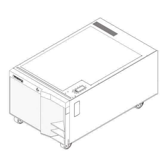
System x3800
Type 8865
Installation Guide
Welcome.
Thank you for buying an
IBM System x server.
is based on the X-Architecture
technology, and it features
superior performance, availability,
and scalability.
Installation Guide
This server
contains information for setting
up and configuring your server.
For detailed information about
your server, view the publications
on the
Documentation CD.
You can also find the most
current information about your
server on the IBM Web site at:
http://www.ibm.com/support
Install options:
Your server
configure hardware
Install applications,
such as IBM systems
management software
and IBM ServeRAID
programs
System is ready to use.
Go to the Server Support
flowchart to register
and profile your server.
Drives
Microprocessors
Adapters
Memory
Cable the server
and options
Start the server
No
Did the server
start correctly?
Yes
Use ServerGuide
to set up and
No
Did configuration
complete?
Yes
Use
No
ServerGuide to
install operating
system?
Yes
Go to the Server Support
flowchart
Go to the Web for instructions,
http://www.ibm.com/support
Advertisement
Table of Contents

Related Manuals for IBM 8865


Summary of Contents for IBM 8865
- Page 1 Documentation CD. You can also find the most current information about your ServerGuide to Go to the Web for instructions, server on the IBM Web site at: install operating http://www.ibm.com/support http://www.ibm.com/support system? Install applications, such as IBM systems...
- Page 2 Check all cables for loose connections and verify that all optional devices you installed are on the ServerProven list at http://www.ibm.com/servers/eserver/ serverproven/compat/us/. View information about IBM Support Line at http://www.ibm.com/services/sl/products/ or view support telephone numbers at Is the problem http://www.ibm.com/planetwide/.
- Page 3 IBM System x3800 Type 8865 Installation Guide...
- Page 4 Note: Before using this information and the product it supports, read the general information in “Notices” on page 61, and the Warranty and Support Information document on the IBM Documentation CD. Third Edition (April 2006) © Copyright International Business Machines Corporation 2006. All rights reserved.
-
Page 5: Table Of Contents
Chapter 1. Introduction ..... . 1 The IBM Documentation CD ....2 Hardware and software requirements . - Page 6 Japanese Voluntary Control Council for Interference (VCCI) statement . . . 66 Index ......67 IBM System x3800 Type 8865: Installation Guide...
-
Page 7: Safety
Vor der Installation dieses Produkts die Sicherheitshinweise lesen. Prima di installare questo prodotto, leggere le Informazioni sulla Sicurezza. Les sikkerhetsinformasjonen (Safety Information) før du installerer dette produktet. Antes de instalar este produto, leia as Informações sobre Segurança. © Copyright IBM Corp. 2006... - Page 8 All caution and danger statements in this documentation begin with a number. This number is used to cross reference an English caution or danger statement with translated versions of the caution or danger statement in the IBM Safety Information book.
- Page 9 Statement 1: DANGER Electrical current from power, telephone, and communication cables is hazardous. To avoid a shock hazard: v Do not connect or disconnect any cables or perform installation, maintenance, or reconfiguration of this product during an electrical storm. v Connect all power cords to a properly wired and grounded electrical outlet.
- Page 10 Statement 2: CAUTION: When replacing the lithium battery, use only IBM Part Number 33F8354 or an equivalent type battery recommended by the manufacturer. If your system has a module containing a lithium battery, replace it only with the same module type made by the same manufacturer.
- Page 11 Statement 4: ≥ 18 kg (39.7 lb) ≥ 32 kg (70.5 lb) ≥ 55 kg (121.2 lb) CAUTION: Use safe practices when lifting. Statement 5: CAUTION: The power control button on the device and the power switch on the power supply do not turn off the electrical current supplied to the device.
- Page 12 There are no serviceable parts inside these components. If you suspect a problem with one of these parts, contact a service technician. Statement 10: CAUTION: Do not place any object on top of rack-mounted devices. IBM System x3800 Type 8865: Installation Guide...
-
Page 13: Chapter 1. Introduction
This Installation Guide contains instructions for setting up your IBM System x3800 Type 8865 server and basic instructions for installing some options. More detailed instructions for installing options are in the User’s Guide on the IBM Documentation CD, which comes with the server. This document contains information about:... -
Page 14: The Ibm Documentation Cd
. The IBM Documentation CD The IBM Documentation CD contains documentation for the server in Portable Document Format (PDF) and includes the IBM Documentation Browser to help you find information quickly. Hardware and software requirements The IBM Documentation CD requires the following minimum hardware and software: ®... -
Page 15: Notices And Statements In This Document
Notices and statements in this document The caution and danger statements that appear in this document are also in the multilingual Safety Information document, which is on the IBM Documentation CD. Each statement is numbered for reference to the corresponding statement in the Safety Information document. -
Page 16: Features And Specifications
– Server on: 8% to 80% v Standard: Two 775 watt 110 V or 220 V – Server off: 8% to 80% ac input dual-rated power supplies v Upgradeable to three power supplies IBM System x3800 Type 8865: Installation Guide... -
Page 17: Major Components Of The Server
Major components of the server Blue on a component indicates touch points, where you can grip the component to remove it from or install it in the server, open or close a latch, and so on. Orange on a component or an orange label on or near a component indicates that the component can be hot-swapped, which means that if the server and operating system support hot-swap capability, you can remove or install the component while the server is running. - Page 18 IBM System x3800 Type 8865: Installation Guide...
-
Page 19: Chapter 2. Installing Options
Chapter 2. Installing options This chapter provides basic instructions for installing hardware options in the server. These instructions are intended for users who are experienced with setting up IBM server hardware. If you need more detailed instructions, see the User’s Guide on the IBM Documentation CD. -
Page 20: Working Inside The Server With The Power On
To reduce the possibility of damage from electrostatic discharge, observe the following precautions: v Limit your movement. Movement can cause static electricity to build up around you. IBM System x3800 Type 8865: Installation Guide... -
Page 21: Removing The Front Cover, Top Cover, And Bezel
v The use of a grounding system is recommended. For example, wear an electrostatic-discharge wrist strap, if one is available. Always use an electrostatic-discharge wrist strap or other grounding system when working inside the server with the power on. v Handle the device carefully, holding it by its edges or its frame. v Do not touch solder joints, pins, or exposed circuitry. -
Page 22: Removing The Top Cover
Removing the bezel On a tower model, make sure that you unlock or remove the front cover before you remove the top cover and bezel. To remove the bezel, complete the following steps: IBM System x3800 Type 8865: Installation Guide... -
Page 23: Installing A Hot-Swap Hard Disk Drive
Bezel 1. Press on the two release latches at the top edge of the bezel, and pull the top of the bezel slightly away from the server. 2. Lift the bezel to release the two tabs at the bottom edge of the bezel. 3. -
Page 24: Installing Additional Dimms
You can configure your server to use memory mirroring and memory scrubbing. For detailed information about configuring your server and using these features, see the User’s Guide on the IBM Documentation CD. v To use the hot-add and hot-swap memory features, you must reconfigure your server using the Configuration/Setup Utility program. -
Page 25: Installing A Dimm
Install the DIMMs on each memory card in the order shown in the following table. Each memory card must have at least one pair of DIMMs. See the User’s Guide on the IBM Documentation CD for additional memory configuration installation sequences. - Page 26 7. Touch the static-protective package that contains the DIMM to any unpainted metal surface on the server. Then, remove the DIMM from the package. 8. Turn the DIMM so that the DIMM keys align correctly with the slot. IBM System x3800 Type 8865: Installation Guide...
-
Page 27: Installing A Memory Card
DIMM Retaining clip 9. Insert the DIMM into the connector by aligning the edges of the DIMM with the slots at the ends of the DIMM connector. Firmly press the DIMM straight down into the connector by applying pressure on both ends of the DIMM simultaneously. -
Page 28: Installing An Additional Microprocessor
For details about handling these devices, see “Handling static-sensitive devices” on page 8. 3. Remove the front cover (tower model only), bezel, and the top cover (see “Removing the front cover, top cover, and bezel” on page 9). IBM System x3800 Type 8865: Installation Guide... - Page 29 4. Remove all fans from the server. 5. Remove all memory cards from the server. 6. Remove the bezel (see “Removing the bezel” on page 10). 7. Remove the microprocessor tray: a. Open the microprocessor-tray release latch. Microprocessor-tray release latch Air baffle Microprocessor-tray lever...
- Page 30 Press down on one side of the heat-sink retention clip to release it from the side of the socket; then, repeat the process on the opposite side. b. Rotate the heat-sink retention clip forward to its fully open position. IBM System x3800 Type 8865: Installation Guide...
- Page 31 11. Remove the protective cover, tape, or label from the surface of the microprocessor socket, if any is present. 12. Lift the microprocessor-release lever to the fully-open position (approximately 135° angle). Lever fully open Lever closed 13. Touch the static-protective package that contains the new microprocessor to any unpainted metal surface on the server;...
-
Page 32: Installing An Adapter
The following sections describe how to install adapters in the server. Installing the Remote Supervisor Adapter II SlimLine An optional IBM Remote Supervisor Adapter II SlimLine can be installed only in its dedicated connector on the I/O board. The following illustration shows how to install a Remote Supervisor Adapter II SlimLine. -
Page 33: Installing A Serveraid-8I Adapter
The ServeRAID-8i adapter is not cabled to the server, and no rerouting of the SAS cables is required. The following illustration shows how to install a ServeRAID-8i adapter. ServeRAID-8i adapter ServeRAID-8i slot For more detailed instructions or information, see the User’s Guide on the IBM Documentation CD. Chapter 2. Installing options... -
Page 34: Installing A Hot-Plug Adapter
For details, see the documentation that comes with the adapter. For more detailed instructions and information about installing PCI/PCI-X adapters, see the section about installing options in the User’s Guide on the IBM Documentation CD. 1. Read the safety information that begins on page v and “Installation guidelines”... -
Page 35: Completing The Installation
5. Install the adapter: a. Open the blue adapter guide by lifting the front edge. b. Push the orange adapter retention latch toward the rear of the server and open the tab. The power LED for the slot turns off if an adapter is installed in the slot. - Page 36 1. Insert the two tabs on the bottom of the bezel into the matching holes on the server chassis. 2. Push the top of the bezel toward the server until the locking tabs at the top of the bezel snap into place. IBM System x3800 Type 8865: Installation Guide...
-
Page 37: Connecting The Cables
Installing the front cover To install the front cover (tower model), complete the following steps. Unlock Lock 1. Insert the two tabs on the bottom of the front cover into the matching holes on the bezel. 2. Push the top of the front cover toward the server until the two release latches at the top of the bezel snap into place. -
Page 38: Updating The Server Configuration
(SMP) server. You might have to upgrade the operating system to support SMP. For more information, see the section about using the ServerGuide Setup and Installation CD in the User’s Guide on the IBM Documentation CD and the operating-system documentation. -
Page 39: Chapter 3. Server Controls, Connectors, Leds, And Power
The following controls, connectors, and LEDs are on the operator information panel: v USB connector: Connect a USB device to this connector. v Power-control button: Press this button to turn the server on and off manually. A power-control-button shield comes with the server. © Copyright IBM Corp. 2006... - Page 40 CD drive activity LED: When this LED is lit, it indicates that the CD drive is in use. CD-eject button: Press this button to release a CD or DVD from the DVD drive. IBM System x3800 Type 8865: Installation Guide...
-
Page 41: Rear View
Rear view The following illustration shows the connectors and LEDs on the rear of the server. SP Ethernet 10/100 activity LED SP Ethernet SP Ethernet 10/100 10/100 link LED USB 2 USB 1 System serial Power-supply Video SP serial AC power DC power Fan error Gigabit Ethernet 1... - Page 42 Remote Supervisor Adapter II SlimLine error LED: This LED is on the I/O board and is visible on the rear of the server. When this LED is lit, it indicates that there is a problem with the IBM Remote Supervisor Adapter II SlimLine. ™...
-
Page 43: Server Power Features
Server power features When the server is connected to an ac power source but is not turned on, the operating system does not run, and all core logic except for the service processor is shut down; however, the server can respond to requests from the service processor, such as a remote request to turn on the server. - Page 44 If the Wake on LAN feature turned on the server, the Wake on LAN feature can turn off the server. v You can turn off the server through a request from the service processor. IBM System x3800 Type 8865: Installation Guide...
-
Page 45: Chapter 4. Configuring The Server
Chapter 4. Configuring the server The ServerGuide Setup and Installation CD provides software setup tools and installation tools that are specifically designed for your IBM server. Use this CD during the initial installation of the server to configure basic hardware features and to simplify the operating-system installation. -
Page 46: Installing And Using The Baseboard Management Controller Utility Programs
Any standard Telnet client application can access the SOL connection. See the User’s Guide on the IBM Documentation CD for details. For more information about IPMI 2.0, see the Intelligent Platform Management Interface Specification (IPMI Specification), version 2.0, available at... -
Page 47: Using The Sas/Sata Configuration Utility Program
ServeRAID controller. For information about these programs, see the documentation that comes with the ServeRAID controller and the User’s Guide on the IBM Documentation CD. If your server comes with an operating system installed, such as Microsoft Windows 2000 Datacenter Server, see the software documentation that comes with the server for configuration information. -
Page 48: Using The Remote Supervisor Ii Web Interface
The following cable connections are required: – Crossover cable from the SP connector to a computer. – An Ethernet cable that is connected to an Ethernet network. See the User’s Guide on the IBM Documentation CD for instructions. IBM System x3800 Type 8865: Installation Guide... -
Page 49: Chapter 5. Solving Problems
If you cannot locate and correct the problem using the information in this chapter, see Appendix A, ″Getting help and technical assistance″ in the Problem Determination and Service Guide on the IBM Documentation CD, and the “Server Support” flowchart in the front of this document. -
Page 50: Post Error Codes
The following table provides an abbreviated list of the error codes and messages that might appear during POST. See the Problem Determination and Service Guide on the IBM Documentation CD for more information about the POST error codes and messages. See http://www.ibm.com/support/ to check for updated technical information. - Page 51 v Follow the suggested actions in the order in which they are listed in the Action column until the problem is solved. v See the parts listing in the Problem Determination and Service Guide to determine which components are customer replaceable units (CRU) and which components are field replaceable units (FRU). v If an action step is preceded by “(Trained service technician only),”...
-
Page 52: Troubleshooting Tables
Troubleshooting tables The following tables list problem symptoms and suggested solutions. See the Problem Determination and Service Guide on the IBM Documentation CD for more detailed troubleshooting information. If you cannot find the problem in these charts, run the diagnostic programs. If you have run the diagnostic programs, or if running the tests does not diagnose the problem, call for service. - Page 53 v Follow the suggested actions in the order in which they are listed in the Action column until the problem is solved. v See the parts listing in the Problem Determination and Service Guide to determine which components are customer replaceable units (CRU) and which components are field replaceable units (FRU). v If an action step is preceded by “(Trained service technician only),”...
- Page 54 4. Reseat the following components: a. Mouse or pointing device b. I/O board 5. Replace the components listed in step 4 one at a time, in the order shown, restarting the server each time. IBM System x3800 Type 8865: Installation Guide...
- Page 55 v Follow the suggested actions in the order in which they are listed in the Action column until the problem is solved. v See the parts listing in the Problem Determination and Service Guide to determine which components are customer replaceable units (CRU) and which components are field replaceable units (FRU). v If an action step is preceded by “(Trained service technician only),”...
- Page 56 Remote Supervisor Adapter II SlimLine (if one is present) b. I/O board 5. Replace the components listed in step 4 one at a time, in the order shown, restarting the server each time. IBM System x3800 Type 8865: Installation Guide...
- Page 57 v Follow the suggested actions in the order in which they are listed in the Action column until the problem is solved. v See the parts listing in the Problem Determination and Service Guide to determine which components are customer replaceable units (CRU) and which components are field replaceable units (FRU). v If an action step is preceded by “(Trained service technician only),”...
- Page 58 To prevent diskette drive read/write errors, make sure that the distance between the monitor and any external diskette drive is at least 76 mm (3 in.). b. Non-IBM monitor cables might cause unpredictable problems. 2. Reseat the following components: a. Monitor b.
- Page 59 If an action step is preceded by “(Trained service technician only),” that step must be performed only by a trained service technician. An IBM optional device that 1. Make sure that all of the hardware and cable connections for the device are used to work does not work secure.
- Page 60 6. If you just installed an optional device, remove it, and restart the server. If the server now turns on, you might have installed more devices than the power supply supports. IBM System x3800 Type 8865: Installation Guide...
- Page 61 The serial-port adapter (if one is present) is seated correctly. 2. Reseat the serial port adapter. 3. Replace the serial port adapter. For more information about the serial port, see the User’s Guide on the IBM Documentation CD. A serial device does not work.
-
Page 62: Light Path Diagnostics
Light path diagnostics is a system of LEDs on various external and internal components of the server. When an error occurs, LEDs are lit throughout the server. By viewing the LEDs in a particular order, you can often identify the source of the error. IBM System x3800 Type 8865: Installation Guide... - Page 63 The server is designed so that LEDs remain lit when the server is connected to an ac power source but is not turned on, provided that the power supply is operating correctly. This feature helps you to isolate the problem when the operating system is shut down.
- Page 64 3. To view the light path diagnostics panel, press the release latch on the front of the operator information panel to the left; then, slide it forward. This reveals the light path diagnostics panel. Lit LEDs on this panel indicate the type of error that has occurred. IBM System x3800 Type 8865: Installation Guide...
-
Page 65: Remind Button
Light Path Diagnostics OVER SPEC LINK REMIND DASD RAID NONRED TEMP Look at the system service label on the top of the server, which gives an overview of internal components that correspond to the LEDs on the light path diagnostics panel. This information and the information in “Light path diagnostics panel”... - Page 66 Failing power supply or power supply filler b. (Trained service technician only) Microprocessor tray 5. If a 12 V fault has occurred, remove ac power before restoring dc power. LINK Reserved for future use IBM System x3800 Type 8865: Installation Guide...
- Page 67 v Follow the suggested actions in the order in which they are listed in the Action column until the problem is solved. v See the parts listing in the Problem Determination and Service Guide to determine which components are customer replaceable units (CRU) and which components are field replaceable units (FRU). v If an action step is preceded by “(Trained service technician only),”...
- Page 68 There is a fault in the Remote 1. Reseat the Remote Supervisor Adapter II SlimLine. Supervisor Adapter II SlimLine. 2. Update the firmware for the Remote Supervisor Adapter II SlimLine. 3. Replace the Remote Supervisor Adapter II SlimLine. IBM System x3800 Type 8865: Installation Guide...
- Page 69 v Follow the suggested actions in the order in which they are listed in the Action column until the problem is solved. v See the parts listing in the Problem Determination and Service Guide to determine which components are customer replaceable units (CRU) and which components are field replaceable units (FRU). v If an action step is preceded by “(Trained service technician only),”...
- Page 70 1. (Trained service technician only) Reseat the microprocessor tray. 2. Run diagnostic program 3. (Trained service technician only) Replace the microprocessor tray. I/O BRD The I/O board has failed. 1. Reseat the I/O board. 2. Replace the I/O board. IBM System x3800 Type 8865: Installation Guide...
-
Page 71: Appendix. Getting Help And Technical Assistance
If you need help, service, or technical assistance or just want more information about IBM products, you will find a wide variety of sources available from IBM to assist you. This appendix contains information about where to go for additional information about IBM and IBM products, what to do if you experience a problem with your system or optional device, and whom to call for service, if it is necessary. -
Page 72: Getting Help And Information From The World Wide Web
Getting help and information from the World Wide Web On the World Wide Web, the IBM Web site has up-to-date information about IBM systems, optional devices, services, and support. The address for IBM System x, ® xSeries, and BladeCenter information is http://www.ibm.com/eserver/xseries/. The address for IBM IntelliStation information is http://www.ibm.com/intellistation/. -
Page 73: Notices
Web sites. The materials at those Web sites are not part of the materials for this IBM product, and use of those Web sites is at your own risk. IBM may use or distribute any of the information you supply in any way it believes appropriate without incurring any obligation to you. -
Page 74: Trademarks
When referring to processor storage, real and virtual storage, or channel volume, KB stands for approximately 1000 bytes, MB stands for approximately 1 000 000 bytes, and GB stands for approximately 1 000 000 000 bytes. IBM System x3800 Type 8865: Installation Guide... -
Page 75: Product Recycling And Disposal
IBM makes no representations or warranties with respect to non-IBM products. Support (if any) for the non-IBM products is provided by the third party, not IBM. Some software may differ from its retail version (if available), and may not include user manuals or all program functionality. -
Page 76: Battery Return Program
United States, go to http://www.ibm.com/ibm/environment/ products/batteryrecycle.shtml or contact your local waste disposal facility. In the United States, IBM has established a return process for reuse, recycling, or proper disposal of used IBM sealed lead acid, nickel cadmium, nickel metal hydride, and battery packs from IBM equipment. -
Page 77: Electronic Emission Notices
Properly shielded and grounded cables and connectors must be used in order to meet FCC emission limits. IBM is not responsible for any radio or television interference caused by using other than recommended cables and connectors or by unauthorized changes or modifications to this equipment. -
Page 78: Taiwanese Class A Warning Statement
Taiwanese Class A warning statement Chinese Class A warning statement Japanese Voluntary Control Council for Interference (VCCI) statement IBM System x3800 Type 8865: Installation Guide... -
Page 79: Index
3 heat output 4 DC power LED 30 hot-plug adapter. dimensions 4 See adapter documentation CD 2 hot-swap drive drive installing 11 hot-swap humidity 4 installing 11 drives 4 DVD drive problems 40 © Copyright IBM Corp. 2006... - Page 80 50 FCC, Class A 65 solving problems 37 notices and statements 3 specifications 4 Standby mode 31 statements and notices 3 system-error LED 28 online publications 1 operator information panel 27 IBM System x3800 Type 8865: Installation Guide...
- Page 81 temperature 4 top cover installing 23 removing 10 trademarks 62 troubleshooting chart 40 turning off the server 31 turning on the server 31 UI 36 United States electronic emission Class A notice 65 United States FCC Class A notice 65 Universal Serial Bus (USB) problems 50 updating the firmware code 34 USB connector 27, 29...
- Page 82 IBM System x3800 Type 8865: Installation Guide...
- Page 84 Part Number: 31R1858 Printed in USA (1P) P/N: 31R1858...
Need help?
Do you have a question about the 8865 and is the answer not in the manual?
Questions and answers