Table of Contents
Advertisement
Quick Links
EVERLAST
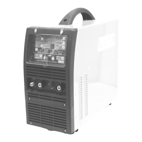
POWERTIG 350 EXT
Digitally Controlled AC/DC Pulse TIG/Stick Welder
CC
GTAW-P
SMAW
IGBT
AC/DC
Operator's Manual for the PowerTIG 350 EXT
Safety, Setup and General Use Guide
Rev.3
0 030103-17
everlastwelders.com
1-877-755-9353
Specifications and Accessories subject to change without notice.
329 Littlefield Ave. South San Francisco, CA 94080 USA
Advertisement
Table of Contents

Related Manuals for Everlast POWERTIG 350 EXT


Summary of Contents for Everlast POWERTIG 350 EXT
- Page 1 EVERLAST POWERTIG 350 EXT Digitally Controlled AC/DC Pulse TIG/Stick Welder GTAW-P SMAW IGBT AC/DC Operator’s Manual for the PowerTIG 350 EXT Safety, Setup and General Use Guide Rev.3 0 030103-17 everlastwelders.com 1-877-755-9353 Specifications and Accessories subject to change without notice.
-
Page 2: Table Of Contents
The owner of this product assumes all liability for its use and maintenance. Everlast Power Equipment INC. does not warrant this product or this document for fitness for any particular purpose, for performance/accuracy or for suitability of application. -
Page 3: Letter To The Customer
Your unit registration is important should any information such as product up- dates or recalls be issued. It is also important so that we may track your satisfaction with Everlast products and services. If you are unable to register by website, contact Everlast directly through the sales department through the main customer service number in your country. -
Page 4: Everlast Contact Information
Serial number: __________________________ Model number: ____________________________ Date of Purchase___________________________ Everlast US: Everlast consumer satisfaction email: sales@everlastwelders.com Everlast Website: everlastwelders.com Everlast Technical Support: support@everlastwelders.com Everlast Support Forum: http://www.everlastgenerators.com/forums/index.php Main toll free number: 1-877-755 WELD (9353) 9am—5pm PST M-F 11am-4pm PST Sat. -
Page 5: Safety Precautions
Safety Precautions Everlast is dedicated to providing you with the best possible equipment and service to meet the demanding jobs that you have. We want to go beyond delivering a satisfactory product to you. That is the reason we offer technical support to assist you with your needs should an oc- casion occur. - Page 6 Safety Precautions These safety precautions are for protection of safety and health. Failure to follow these guidelines may result in serious injury or death. Be careful to read and follow all cautions and warnings. Protect yourself and others. Welding and cutting processes produce high levels of ultraviolet (UV) radiation that can cause se- vere skin burn and damage.
- Page 7 Safety Precautions WARNING! Persons with pacemakers should not weld, cut or be in the welding area until they consult with their physician. Some pacemakers are sensitive to EMF radiation and could severely malfunction while welding or while being in the vicinity of someone welding. Serious injury or death may occur! Welding and plasma cutting processes generate electro-magnetic fields and radiation.
- Page 8 Safety Precautions WARNING! Electrical shock can kill. Make sure all electrical equipment is properly grounded. Do not use frayed, cut or otherwise damaged cables and leads. Do not stand, lean or rest on ground clamp. Do not stand in water or damp areas while welding or cutting. Keep work surface dry. Do not use welder or plasma cutter in the rain or in extremely humid conditions.
-
Page 9: Introduction And Specifications
Section 1 Introduction and Specifications PowerTIG 350 EXT Accessories Accessory 26 Series TIG torch and cable 18 Series TIG torch and cable Everlast 22k Ω Pedal Heavy duty work clamp Heavy duty electrode holder Regulator and hose assy. NOTE: Accessory and consumable appearance, style, length and quantity subject to change without notice. -
Page 10: Unit Specifications
Section 1 Introduction and Specifications PowerTIG 350EXT TIG/Stick Welder Specifications Process AC/DC GTAW-P/DC SMAW Inverter Type Digital Microprocessor Controlled, IGBT Module Minimum/Maximum Rated Output TIG DC 5A/10.2V– 350 A/24V AC 10A/10.4V– 350 A/240V Minimum/Maximum Rated Output Stick (DC Only) 20 A/20.8V - 270 A/24V Start Type Solid State HF and Lift Start HF Point Gap... -
Page 11: General Overview
Everlast. With a micro- Do not mount in areas that are prone to severe shock processor and IGBT module design, the welder offers or vibration. -
Page 12: Quick Setup Guide, Tig Torch/Cooler Connection
Section 2 Quick Setup and Use Guide QUICK SETUP GUIDE: TIG CONNECTIONS NOTE: The TIG torch will always be negative polarity whether DC or AC! TORCH (-) 9/17 SERIES TORCH WORK (+) 35 SERIES CONNECTOR 35 SERIES CONNECTOR AIR-COOLED TORCH GAS (Ar) CONTROL CONTROL... -
Page 13: Quick Setup Guide, Stick Polarity
Section 2 Quick Setup and Use Guide QUICK SETUP GUIDE: STICK POLARITY AND CONNECTIONS WORK (-) TORCH (+) NOTE: In stick mode, the polarity will almost always be positive, except for special rods or circumstanc- es. Consult the electrode manufacturer packaging material or website for proper polarity with specialty rods and for conditions where electrode negative would be appropriate. -
Page 14: Rear Panel Gas Connection And Wiring
SUPPLIED PLUG IS A NEMA 6-50P, THE STANDARD PLUG FOR MOST 1 PHASE 240 V WELDERS IN THE US AND CANADA. GREEN GROUND 220V/240V COOLER OUTLET. USE WITH EVERLAST POWERCOOL WC 300 ONLY. WARNING: DO NOT USE THIS OUTLET FOR ANY OTHER APPLICATION OR SERVICE! L2,WHITE L1,BLACK;... -
Page 15: Front Panel Features And Controls
Section 2 Quick Setup and Use Guide FRONT PANEL FEATURES AND CONTROLS POWERTIG 350 EXT 1. CLEAR PROTECTIVE PANEL COVER 2. CONTROL PANEL 350EXT 3. NEGATIVE CONNECTOR 6. POSITIVE CONNECTOR DINSE 35-70mm² DINSE 35-70mm² 4.GAS OUTLET QUICK CONNECT 5. 7-PIN CONTROL FOR PEDAL/TORCH SWITCH/AMPTROL... - Page 16 Section 2 Quick Setup and Use Guide FRONT PANEL FEATURES AND CONTROLS POWERTIG 350 EXT POWERTIG 350 EXT PARAMETERS PURPOSE 1. Protective Cover Clear hinged cover protects panel from damage. Keep closed during welding opera- tions. 2. Main Control Panel Digital The main control features digital adjustment.
- Page 17 Section 2 Quick Setup and Use Guide FRONT PANEL FEATURES AND CONTROLS POWERTIG 350 EXT POWERTIG 350 EXT PARAMETERS PURPOSE 1. Memory Function The unit has 9 programs which allow the operator to select parameters and hen save the settings to the selected program channel. To operate, use the selector button to select the desired program number where the program is to be assigned.
- Page 18 Section 2 Quick Setup and Use Guide FRONT PANEL FEATURES AND CONTROLS POWERTIG 350EXT POWERTIG 350EXT PARAMETERS PURPOSE 5. Upslope 0-25 Seconds Upslope ramps “up” from the start amp value to the welding amp value while starting the weld puddle. For best operation, the value will be automatically be set to 0 with standard foot pedal mode.
- Page 19 Section 2 Quick Setup and Use Guide FRONT PANEL FEATURES AND CONTROLS POWERTIG 350EXT POWERTIG 350 EXT PARAMETERS PURPOSE 12. Down Slope 0-25 Seconds Down Slope will ramp amps “down” from the welding amp value to the end amp value to give time to fill the crater left at the end of the weld bead.
- Page 20 Section 2 Quick Setup and Use Guide FRONT PANEL FEATURES AND CONTROLS POWERTIG 255EXT POWERTIG 255EXT PARAMETERS PURPOSE 21. 2T/4T/ Pedal Selector 2T, 4T, Pedal, This selects the operation of the torch switch, pedal, or hand amptrol. To weld with the torch Pedal with 2T, switch, select 2T or 4T.
-
Page 21: Rear Panel Features And Controls
Section 2 Quick Setup and Use Guide REAR PANEL FEATURES AND CONTROLS 350 EXT 1x240V... - Page 22 4. Power Cord 240 V 1 phase The PowerTIG 350 EXT operates on 240V power(±10%). The unit uses a NEMA 6-50 plug for 240V power. This is a standard plug designated for welder use. NOTE: There is NO neutral in a standard 220V welder circuit. A welder circuit will only use three wires (two hot 110V power legs and one ground).
-
Page 23: Welder Function Summary And Explanations
In this case, the amptrol should be used in direction. the foot pedal mode, or 2T pedal mode only depending upon amptrol switch configuration. Everlast sells torches with built in amptrols that are designed for use with our units in the amptrol 2T and 4T mode. Torches... - Page 24 Section 3 Basic Theory and Function have little or no way to change the ratio of EN to EP, 3. AC Wave Forms. The wave form control is a which results in welding with a molten ball at the tip useful feature for achieving a desired type of arc of the tungsten and a less stable arc.
- Page 25 Section 3 Basic Theory and Function EXAMPLE: AC EP (+) BALANCE Parameter Notes: 1 Hz (one full AC cycle) EP 50% EN 50% Standard transformer welder balance 50% EN/EP= Balling tungsten, light penetration, wide cleaning area. EP 65% EN 35% Extreme cleaning setting 65% EP= Shallow penetration, balling tungsten, excessive cleaning area.
- Page 26 Section 3 Basic Theory and Function 6. Standard Pulse. (AC and DC) The pulse creates two EXAMPLE 1 amp values, a high and a low value that cycle back and Welding Amps: 100 amps, forth between each other while welding. The upper PulseAmps: 50% amperage is called the “welding amps”...
- Page 27 For more accurate and responsive the same function as the standard pulse mode adjust- control, Everlast offers a US made foot pedal available as ments. Occasionally during use, a slight wobble of the an additional option. Do not attempt to control stick func- arc may be seen as it pulses between AC and DC—.
- Page 28 The unit will revert to the “setting” mode and display more consumables fairly quickly. These can be bought selected maximum amperage. directly from Everlast in single pieces or in kits. But the consumables are not exclusive to Everlast and may be purchased locally at most any welding supply store which sell TIG welding supplies.
-
Page 29: Tungsten Preparation
Section 3 Basic Theory and Function TUNGSTEN PREPARATION 1. Use a dedicated grinding wheel or contamination may re- sult. Do not breath grinding dust! Wear eye protection and gloves. 2. Hold Tungsten firmly. 3. Grind perpendicular to grind- ing wheel face. Allow tungsten to grind away slowly, creating point. -
Page 30: Lift Start And High Frequency Start
Section 3 Basic Theory and Function LIFT START TIG OPERATION Note: A Lift TIG start should be done with a nearly seamless motion. Use a light touch and a quick motion for best results. FOR DC USE. NOT RECOMMENED FOR AC. <1/8”... -
Page 31: Stick Starting Methods
Section 3 Basic Theory and Function STICK OPERATION STARTING METHODS Tapping Method Scratch/Match Method 1. Turn on the power switch on the rear of the unit. Allow unit to cycle through its start up program. 2. Select the Stick mode or Stick VRD with the HF/Lift Start/Stick/ VRD selector button 3. -
Page 32: Recommendations For Polarity/Amps/Tungsten
Section 3 Basic Theory and Function GENERAL POLARITY RECOMMENDATIONS* *Follow manufacturer of stick electrode for complete polarity recommendations PROCESS TORCH POLARITY WORK POLARITY TIG (GTAW) STICK (SMAW) TIG (GTAW) OPERATION GUIDE FOR STEEL (ALUMINUM)* *As a general rule, set amperage using 1 amp for every .001” of metal thickness for aluminum. Less is required for DC. METAL THICKNESS WELDING AMPS TUNGSTEN DIA. -
Page 33: Expanded View Of Tig Torch
Section 3 Basic Theory and Function EXPANDED VIEW OF TIG TORCH (Actual appearance may vary slightly from what is listed.) 5/8” TYPICAL PARTS FOR Standard Series Torch ( STYLE MAY VARY) QTY. Long Back Cap with O-Ring Short Back Cap Opt. -
Page 34: Pin Connector Pinout
Section 3 Basic Theory and Function 7 PIN CONNECTOR FOR 22K Ω FOOT PEDAL Bridge a Jumper to Pin 7 To Pedal or Torch Switch ON/OFF Bridge a Jumper to Pin 6 To Pedal or Torch Switch ON/OFF Middle High Potentiometer (VR) Foot Pedal (22k Ω) Note: This unit is equipped with a 22K (25K) pedal. -
Page 35: Troubleshooting
Check gas flow. Adjust for higher flow of gas. Listen for audible click of gas solenoid. If no click is heard, then contact Everlast Support. Clean weld properly, espe- cially in Aluminum. Too short of post flow time. Check tungsten stick out. -
Page 36: Trouble Codes
Check foot pedal for complete return or stuck micro-switch. Do not hold down the switch or pedal without attempting to strike an arc. Doing so for more than 2 seconds without starting will cause this error code. OTHER CONTACT EVERLAST... - Page 37 Notes:...
Need help?
Do you have a question about the POWERTIG 350 EXT and is the answer not in the manual?
Questions and answers