
Subscribe to Our Youtube Channel
Related Manuals for WIA CP125-2


Summary of Contents for WIA CP125-2
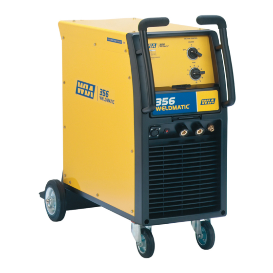
- Page 1 ® Weldmatic 356 [external wirefeeder] Operators Manual Weldmatic 356 MIG welder Model No. CP125-2, Iss A 05/09 CP125-40 Rev B...
- Page 2 Welding Industries of Australia An ITW Company ABN 18 004 547 111 Telephone: 1300 300 884 Facsimile: 1300 301 884 Email: Info@welding.com.au www.welding.com.au...
-
Page 3: Table Of Contents
Weldmatic 356 Contents Section General Information Page Safe Practices Introduction Receiving Specifi cations Controls Installation Normal Welding Sequence Basic Welding Information General Maintenance External Trouble Shooting Circuit Diagram Assembly and Parts Lists Warranty information Model No CP125-2, Iss A 05/09... -
Page 4: Safe Practices
Operators Manual Safe Practices When Using Read first Welding Equipment The information contained in this These notes are provided in the interests manual is set out to enable you to of improving operator safety. They should properly maintain your new equipment be considered only as a basic guide to Safe and ensure that you obtain maximum Working Habits. - Page 5 Walls, Metals coated with or containing materials ceilings, and floor near work should be that emit fumes should not be heated unless protected by heat-resistant covers or shields. Model No CP125-2, Iss A 05/09...
- Page 6 Operators Manual A person acting as Fire Watcher must be Shock Prevention standing by with suitable fire extinguishing Exposed conductors or other bare metal equipment during and for some time after in the welding circuit, or ungrounded welding or cutting if; electrically alive equipment can fatally shock •...
-
Page 7: Introduction
The arc and the weld pool are both shielded by gas flow from the gun, or • Weldmatic 356 Power Source CP125-2 in the case of “self shielded” wires, by gases • (This) Operating Manual CP125-40. generated by the wire core. -
Page 8: Specifications
Operators Manual 3 Specifications Power Source Cooling Manufactured to Australian Standard Fan on demand, fan operates only as required to cool internal components AS60974-1. Insulation Primary Voltage Class H, 140°C Rise 415 Vac, 50Hz Wirefeeder Circuit Breaker Rating Rated Primary Current 5 Amps 15 Amps Maximum Primary Current... -
Page 9: Controls
This switch provides mains power ON/ OFF and Coarse adjustment of the output welding voltage over three ranges. 4 Fine Voltage Control This switch provides Fine adjustment of the output welding voltage over ten steps. Model No CP125-2, Iss A 05/09... -
Page 10: Installation
Operators Manual 5 Installation Connection to Electrical Mains Power Output Voltage Polarity Supply The design of the Weldmatic 356 allows selection of the output voltage polarity. NOTE. All electrical work shall only be Positive Wire undertaken by a qualified electrician. G.M.A.W. - Page 11 Weldmatic 356 power source via the composite cable interconnecting lead. Check all connections are fi rmly made to ensure good electrical contact, and to prevent gas leaks. To wirefeeder To work clamp Fig 3 Negative Wire Model No CP125-2, Iss A 05/09...
-
Page 12: Normal Welding Sequence
Operators Manual 6 Normal Welding Sequence 7 Basic Welding Information Weld Start Choice of Shielding Gas Closing the welding gun switch initiates this The choice of shielding gas is largely sequence of events: determined by the consumable wire to be used. Many proprietary shielding gas •... - Page 13 This lack of fusion would normally be corrected by increasing the arc voltage, or by increasing both wirefeed speed and arc voltage to achieve a higher current weld setting. Model No CP125-2, Iss A 05/09...
-
Page 14: General Maintenance
Operators Manual 8 General Maintenance Gun Position Before removing the power For “down hand” fillet welding, the gun is source covers, ENSURE that the normally positioned as shown in Figure 6 equipment is disconnected from below with the nozzle end pointing in the the mains power supply. -
Page 15: External Trouble Shooting
1 Check the rating of the mains supply gun adaptor are making contact with circuit breaker. The Weldmatic 356 should the mating pins from the gun end. be supplied from a 20 Amp or larger circuit breaker. Model No CP125-2, Iss A 05/09... - Page 16 Operators Manual Porosity (honeycomb appearance) in Unsatisfactory Welding Performance weld and Results 1 Check the gun nozzle and gas diffuser Erratic arc characteristics caused by poor holes are free from spatter and firmly wirefeed attached to the welding gun to ensure that no air is being drawn into the Erratic wirefeed is the MOST LIKELY cause of shielded area...
-
Page 17: Circuit Diagram
Weldmatic 356 10 Circuit Diagrams - Power Source Fig 7 Power Source Circuit Diagram Model No CP125-2, Iss A 05/09... -
Page 18: Assembly And Parts Lists
Operators Manual 11 Assembly and Parts List - Weldmatic 356 Power Source 14 15 Fig 8 Weldmatic 356 Power Source Assembly Quality Reliability Performance • •... - Page 19 Thermostat (included in rectifier) IND022 Inductance Assembly CP104-16/2 Thermal Overload (included with Inductance Assembly) TFM046N Welding Transformer Assembly, Wired FAN005 Fan Assembly PAN095 Back Panel EO047 Contactor Not shown R0028 Fan On Demand Thermistor Model No CP125-2, Iss A 05/09...
-
Page 20: Warranty Information
Subject to the terms and conditions below, 2 Equipment that has been modified by any WIA warrants to its original retail purchaser that party other than WIA, or equipment that new WIA equipment sold after the effective has been improperly installed, improperly... - Page 21 WIA’s option of repair or replacement will be F. O. B. Factory at Melrose Park, Adelaide, or F. O. B. at a WIA authorised service facility as determined by WIA. Therefore no compensation or reimbursement for transportation costs of any kind will be allowed.
- Page 22 Operators Manual Notes Quality Reliability Performance • •...
- Page 23 Weldmatic 356 Notes Model No CP125-2, Iss A 05/09...
Need help?
Do you have a question about the CP125-2 and is the answer not in the manual?
Questions and answers