
Related Manuals for WIA WELDMATIC 350


Summary of Contents for WIA WELDMATIC 350
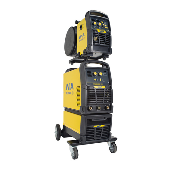
- Page 1 MIG & Multi-Process Welders OPERATORS MANUAL CP144-1, CP145-1 From serial numbers C1442A*/C1452A* WELDING.COM.AU...
- Page 2 WELDING INDUSTRIES AUSTRALIA A Division of ITW Australia Pty Ltd ABN: 63 004 235 063 1300 300 884 Email: info@welding.com.au welding.com.au WELDWELL NEW ZEALAND A Division of ITW New Zealand NZBN: 9 429 039 833 129 GST NO: 080177186 0800 9353 9355 Email: info@weldwell.co.nz weldwell.co.nz...
-
Page 3: Table Of Contents
CONTENTS Section General Information Page Safe Practices Introduction Receiving Specifications Controls Installation Normal Welding Sequence Basic Welding Information General Maintenance External Trouble Shooting Trouble Shooting Chart Service Information 11.1 Circuit Diagram Assembly & Parts Lists 12.1 Power Source 12.2 Welding Torch 350 12.3 Welding Torch 500 Australian Warranty Information... -
Page 4: Safe Practices
Weldmatic 350 & 500 | Operator Manual | Model No CP144-2/CP145-2 SAFE PRACTICES WHEN USING WELDING EQUIPMENT READ FIRST The information contained in this These notes are provided in the interests manual is set out to enable you of improving operator safety. They should... - Page 5 Burn Protection Metals coated with or containing materials that emit fumes should not be heated The welding arc is intense and visibly bright. unless coating is removed from the work Its radiation can damage eyes, penetrate surface, the area is well ventilated, or the light-weight clothing, reflect from light- operator wears an air-supplied respirator.
- Page 6 Weldmatic 350 & 500 | Operator Manual | Model No CP144-2/CP145-2 Walls touching combustibles on opposite Shock Prevention sides should not be welded on or cut. Walls, Exposed conductors or other bare metal ceilings, and floor near work should be in the welding circuit, or ungrounded protected by heat-resistant covers or shields.
-
Page 7: Introduction
WIA supplies a wide range of mild steel and The Weldmatic has been designed to be special purpose electrodes which cater used with consumable wires of different for home workshop, rural, and industrial diameter. -
Page 8: Receiving
Weldmatic 350 & 500 | Operator Manual | Model No CP144-2/CP145-2 2 RECEIVING Austarc 13S, Classification E4313-A Check the equipment received against the shipping invoice to make sure the shipment A smooth running electrode with a soft arc, is complete and undamaged. If any damage... -
Page 9: Specifications
3 SPECIFICATIONS Manufactured to Standards AS60974.1 IEC60974.10 AS60974.1 IEC60974.10 Rated Input Voltage 380 – 415V 3 Phase 380 – 415V 3 Phase Power Frequency 50/60 Hz 50/60 Hz Generator Three Phase Capacity 32KVA 47KVA Rated Maximum Supply Current Imax Maximum Effective 32.5A Supply Current Ieff Output No Load Voltage... -
Page 10: Controls
Weldmatic 350 & 500 | Operator Manual | Model No CP144-2/CP145-2 4 CONTROLS Design WIN649A WIN649A VOLTS ON VRD STICK ARC FORCE AMPS MIG ARC CONTROL PROCESS WIRE STICK MIG VS CORED WIRE (Hold 3 Sec.) - Self/Gas Shielded - All Sizes... - Page 11 9 Weld Current Adjustment 11.3 MIG Arc Control Weld Current Adjustment Knob for Stick When in MIG GMAW mode the harshness MMA or TIG Mode. of the arc can be adjusted. For example aluminium welding would require a different 10 Digital Display Volts setting to steel welding.
-
Page 12: Installation
Weldmatic 350 & 500 | Operator Manual | Model No CP144-2/CP145-2 5 INSTALLATION Connection to Electrical Mains Power Supply The Weldmatic 500 is factory fitted with a Note: All electrical work shall only be 3 metre, 3 core+ earth 4.0mm2 Heavy Duty PVC mains power supply cable. - Page 13 Successful operation Positive Wire Successful operation will depend on a MIG welding (GMAW), with solid number of factors: consumable wires and gas shielding, is carried out with the work piece Negative – Variation in circuit breaker thresholds. and the welding wire Positive. –...
-
Page 14: Normal Welding Sequence
Weldmatic 350 & 500 | Operator Manual | Model No CP144-2/CP145-2 6 NORMAL WELDING 7 BASIC WELDING INFORMATION SEQUENCE MIG Welding (GMAW) Weld Start Choice of Shielding Gas Closing the welding gun switch initiates The choice of shielding gas is largely... - Page 15 Establishing a Weld Setting A “good” weld will have the characteristics illustrated in Figure 2. The weld has penetrated Once the consumable wire type, wire size into the parent metal, fusing the root of the and shielding gas have been chosen, the joint where the two plates meet, and the two variables that are adjusted in order to weld blends smoothly into the side walls.
- Page 16 Weldmatic 350 & 500 | Operator Manual | Model No CP144-2/CP145-2 Gun Position For “down hand” fillet welding with gas shielded solid wires, the gun is normally positioned as shown in Figure 4a below, with the nozzle end pointing in the direction of travel.
- Page 17 Select an appropriate welding current for Current Range for General Purpose the electrode diameter by setting the knob Electrodes on the machine front panel. WIA Austarc electrodes will give the best results. Diameter (mm) Current (Amps) To strike the arc, drag the end of the...
- Page 18 Weldmatic 350 & 500 | Operator Manual | Model No CP144-2/CP145-2 TIG Welding (GTAW) TIG Welding Operation Connect the Work Clamp to the work piece. Connection for TIG Welding Turn on the power switch located on the rear For TIG welding, the torch is connected to panel.
- Page 19 10 min period over 4 hours. The Weldmatic 350 is rated at 350 Amps, and the 500 at 500 Amps, 60% duty cycle. If the machine is operated at a reduced welding current, a higher duty cycle is available.
-
Page 20: General Maintenance
Weldmatic 350 & 500 | Operator Manual | Model No CP144-2/CP145-2 8 GENERAL MAINTENANCE Welding tip is free of obstructions Before removing the equipment such as spatter build-up. Ream out cover, ENSURE that the equipment the tip bore with a suitable size oxy-tip is disconnected from the mains cleaner. -
Page 21: External Trouble Shooting
If you are in Australia and the following checks do not identify the fault condition, the equipment should be returned to a WIA Service agent. Phone 1300 300 884 for details of your nearest service agent. If you are in New Zealand and the... -
Page 22: Trouble Shooting Chart
Weldmatic 350 & 500 | Operator Manual | Model No CP144-2/CP145-2 10 TROUBLE SHOOTING CHART Problem Likely Reason Outcome All Inverter Multi-Process Models No welding current, no The machine is not turned on If confirmed that the machine display. at both the mains supply and is switched on correctly, the machine power switch. - Page 23 Problem Likely Reason Outcome MMA/STICK Models In MMAW (Stick), the arc is The technique required The technique to strike should difficult to strike. for VRD enabled welding be reviewed, not as a ‘strike’ machines is not the same as but more as ‘touch, twist, lift’ earlier stick welding units.
- Page 24 Weldmatic 350 & 500 | Operator Manual | Model No CP144-2/CP145-2 Problem Likely Reason Outcome GMAW/MIG Models (cont.) Wire feed stutters and arc Torch consumables are Liners and contact tips are is erratic. Also, motor turns blocked/partially blocked. consumable and wear over correctly under no load.
-
Page 25: Service Information
11 SERVICE INFORMATION The following information is intended for use by qualified service personnel. When the unit is energised LETHAL VOLTAGES are present on the electrical and electronic components. It is not intended that persons without suitable training and knowledge attempt to perform service tasks on the components of this welder. -
Page 26: Circuit Diagram
Weldmatic 350 & 500 | Operator Manual | Model No CP144-2/CP145-2 11.1 CIRCUIT DIAGRAM - POWER SOURCE Fig 7 Weldmatic 350 + 500 Circuit Diagram... - Page 27 12 ASSEMBLY - WELDMATIC 350/500 27 28 Fig 8 Weldmatic 350 + 500 Assembly...
- Page 28 Weldmatic 350 & 500 | Operator Manual | Model No CP144-2/CP145-2 12.1 PARTS LIST - WELDMATIC 350/500 Item # Part # Description M0111 Handle PAN179 Enclosure 350 PAN189 Enclosure 500 L0036 Control Transformer PWA069 IGBT Driver 350 500 PWA068 PCB Assy Main Control 350...
-
Page 29: Welding Torch 350
12.2 ASSEMBLY AND PARTS LIST - TORCH WELDMATIC 350 Fig 9 350 Amp Gun and Cable Assembly Item # Part # Description see ‘Nozzles’ (page 31) Nozzle see ‘Tips’ (page 31) Contact Tip BED-1 Gas Diffuser, Large BE10012 Insulator BEQT3-45 Body Tube 3”x 45... -
Page 30: Welding Torch 500
Weldmatic 350 & 500 | Operator Manual | Model No CP144-2/CP145-2 12.3 ASSEMBLY AND PARTS LIST - TORCH WELDMATIC 500 Fig 10 400 Amp Gun and Cable Assembly Item # Part # Description see ‘Nozzles’ (page 31) Nozzle see ‘Tips’ (page 31) - Page 31 Nozzles To replace liner: Disconnect gun/cable assembly at the Euro adaptor. Remove nozzle (1) gas diffuser (3) and insulator (4). Part # Description Withdraw old liner from the wirefeeder BEN-3400C Nozzle, copper, 3/4” I.D, end. Insert new liner and refit gun/cable flush assembly to the wirefeeder.
-
Page 32: Australian Warranty Information
Weldmatic 350 & 500 | Operator Manual | Model No CP144-2/CP145-2 AUSTRALIAN WARRANTY INFORMATION Any handling and transportation costs (and other expenses) incurred in claiming under this warranty are not covered by this warranty and will not be borne by Welding Industries of Australia. - Page 33 Our goods come with guarantees that cannot be excluded under the Australian Consumer Law. You are entitled to a replacement or refund for a major failure and for compensation for any other reasonably foreseeable loss or damage. You are also entitled to have the goods repaired or replaced if the goods fail to be of acceptable quality and the failure does not amount to a major failure.
-
Page 34: New Zealand Warranty Information
Weldmatic 350 & 500 | Operator Manual | Model No CP144-2/CP145-2 NEW ZEALAND WARRANTY INFORMATION WIA Weldmatic MIG & Multi-Process Equipment 3 Year Gold Shield Warranty Statement Effective 1st January 2022 WIA Weldmatic MIG & Multi-Process Equipment purchased in New Zealand... - Page 35 NOTES:...
- Page 36 WELDING INDUSTRIES WELDWELL AUSTRALIA NEW ZEALAND A Division of ITW Australia Pty Ltd A Division of ITW New Zealand ABN: 63 004 235 063 NZBN: 9 429 039 833 129 GST NO: 080 177 186 1300 300 884 Email: info@welding.com.au 0800 9353 9355 welding.com.au Email: info@weldwell.co.nz...
Need help?
Do you have a question about the WELDMATIC 350 and is the answer not in the manual?
Questions and answers
disabling vrd on 500i weldmatic
vrd switch