WIA WELDARC 135 Operator's Manual

WIA WELDARC 135 Operator's Manual

Stick/tig welders

Advertisement

Quick Links

Stick/TIG Welders
OPERATORS MANUAL | MC110-0 / MC111-0 / MC112-0
From serial numbers M1102A*, M1112A*, M1122A*
WELDING.COM.AU

Advertisement

Table of Contents
loading
Need help?

Need help?

Do you have a question about the WELDARC 135 and is the answer not in the manual?

Questions and answers

Summary of Contents for WIA WELDARC 135

  • Page 1 Stick/TIG Welders OPERATORS MANUAL | MC110-0 / MC111-0 / MC112-0 From serial numbers M1102A*, M1112A*, M1122A* WELDING.COM.AU...
  • Page 2 WELDING INDUSTRIES AUSTRALIA A Division of ITW Australia Pty Ltd ABN: 63 004 235 063 1300 300 884 Email: info@welding.com.au welding.com.au WELDWELL NEW ZEALAND A Division of ITW New Zealand NZBN: 9 429 039 833 129 GST NO: 080177186 0800 9353 9355 Email: info@weldwell.co.nz weldwell.co.nz...
  • Page 3: Table Of Contents

    CONTENTS Section General Information Page Safe Practices Introduction Receiving Specifications Features 10-11 4.1 VRD 4.2 Fan on Demand 4.3 Shoulder Strap 4.4 Hot Start 4.5 Arc Force 4.6 Power Factor Correction
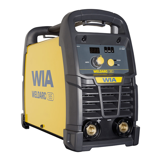
 Controls 145 & 185 Controls 135 Installation Basic Welding Information 14-16 General Maintenance External Trouble Shooting Trouble Shooting Chart...
  • Page 4: Safe Practices

    Weldarc 135, 145, 185 | Operator Manual | Model No MC110-0 / MC111-0 / MC112-0 SAFE PRACTICES WHEN USING WELDING EQUIPMENT READ FIRST These notes are provided in the interests The information contained in this of improving operator safety. They should...
  • Page 5 Burn protection Metals coated with or containing materials that emit fumes should not be heated The welding arc is intense and visibly bright. unless coating is removed from the work Its radiation can damage eyes, penetrate surface, the area is well ventilated, or the light-weight clothing, reflect from light- operator wears an air-supplied respirator.
  • Page 6 Weldarc 135, 145, 185 | Operator Manual | Model No MC110-0 / MC111-0 / MC112-0 Walls touching combustibles on opposite Shock Prevention sides should not be welded on or cut. Walls, Exposed conductors or other bare metal ceilings, and floor near work should be in the welding circuit, or ungrounded protected by heat-resistant covers or shields.
  • Page 7: Introduction

    E316L-16 flux coating of the electrode. For quality all position stainless steel The Weldarc 135, 145 and 185 has been welding. Extra smooth running, high arc designed to be used with 2.0mm, 2.5mm, stability, easy re-strike, excellent slag 3.2mm diameter electrodes, and the 185...
  • Page 8: Receiving

    Weldarc 135, 145, 185 | Operator Manual | Model No MC110-0 / MC111-0 / MC112-0 2 RECEIVING Check the equipment received against the If the supply cable is damaged it must shipping invoice to make sure the shipment be replaced by the manufacturer, their is complete and undamaged.
  • Page 9 WELDARC 135 WELDARC 145 WELDARC 185 Continuous Rated 60 Amp 56 Amp 92 Amp Output@ 40°C Welding Current 20 - 135 Amps 25 - 145 Amps 25 - 185 Amps Open Circuit Voltage Uo = 10V Uo = 23 V...
  • Page 10: Features

    Weldarc 135, 145, 185 | Operator Manual | Model No MC110-0 / MC111-0 / MC112-0 4 FEATURES Change VRD Function 4.1 VRD Function (Voltage Reduction Device) If the VRD function does not suit the application, the VRD can be enabled or The VRD function is a safety feature, to disabled by an authorised WIA service agent.
  • Page 11: Shoulder Strap

    4.3 Shoulder Strap 4.5 Arc Force Arc force is a voltage boost. The extra To attach the shoulder strap to the Weldarc, voltage is used when arc voltage drops due feed the strap through the slot underneath to arc shorts. the handle at front and rear of machine.
  • Page 12: Controls 145 & 185

    Weldarc 135, 145, 185 | Operator Manual | Model No MC110-0 / MC111-0 / MC112-0 5 CONTROLS 145 & 185 POWER SOURCE Power Switch Located on the rear panel WIN628A ON VRD STICK AMPS Note: Control panel diagram instructions are also suited for Weldarc 145 VRD Safe Mode Indicator 4.2 Stick Electrode Welding (MMAW).
  • Page 13: Controls 135

    5.1 CONTROLS 135 POWER SOURCE Approved Design - WIN678B Power Switch Located on the rear panel Mock up with knob. Proof only DO NOT PRINT WIN678B ON VRD AMPS Weld Current Control Power On/Off Switch This control sets the output current level of In the OFF position, this switch isolates the the power source within the available range.
  • Page 14: Installation

    Weldarc 135, 145, 185 | Operator Manual | Model No MC110-0 / MC111-0 / MC112-0 7 BASIC WELDING INFORMATION 6 INSTALLATION Stick Welding (MMAW) Connection to Electrical Mains Power Supply Connection for Stick Welding The Weldarc 135 & 145 is fitted with a 10 Amp It is important to select the electrode supply cable and plug.
  • Page 15 Select an appropriate welding current for Diameter (mm) Current (Amps) the electrode diameter by setting the knob 40 - 60 on the machine front panel. WIA Austarc electrodes will give the best results. 60 - 85 To Strike the Arc: 90 - 130 130 - 180 With VRD enabled, touch-twist-lift.
  • Page 16: General Maintenance

    Weldarc 135, 145, 185 | Operator Manual | Model No MC110-0 / MC111-0 / MC112-0 8 GENERAL MAINTENANCE TIG Welding Operation Before removing the equipment Connect the Work Clamp to the work piece. cover, ENSURE that the equipment is disconnected from the mains Turn on the power switch located on the power supply.
  • Page 17: Trouble Shooting Chart

    10 TROUBLE SHOOTING CHART Problem Likely Reason Outcome All Inverter Multi-Process Models No welding current, no The machine is not turned on If confirmed that the machine display. at both the mains supply and is switched on correctly, the machine power switch. test the same outlet using a known serviceable appliance.
  • Page 18 Weldarc 135, 145, 185 | Operator Manual | Model No MC110-0 / MC111-0 / MC112-0 Problem Likely Reason Outcome MMA/STICK Models In MMAW (Stick), the arc is The technique required The technique to strike difficult to strike. for VRD enabled welding...
  • Page 19: Service Information

    11 SERVICE INFORMATION The electrical components of the equipment are shown in the circuit diagrams on pages 20-22. The Weldarc inverter is an inverter type design, where the mains supply is first rectified, filtered then chopped to a high frequency before being applied to the welding transformer.
  • Page 20: Circuit Diagrams

    Weldarc 135, 145, 185 | Operator Manual | Model No MC110-0 / MC111-0 / MC112-0 12 CIRCUIT DIAGRAMS – 135 POWER SOURCE Fig 5 Weldarc 135 Circuit Diagram...
  • Page 21 12.1 CIRCUIT DIAGRAMS – 145 POWER SOURCE Fig 6 Weldarc 145 Circuit Diagram...
  • Page 22 Weldarc 135, 145, 185 | Operator Manual | Model No MC110-0 / MC111-0 / MC112-0 12.2 CIRCUIT DIAGRAMS – 185 POWER SOURCE Fig 7 Weldarc 185 Circuit Diagram...
  • Page 23 13 ASSEMBLY AND PARTS LIST - WELDARC 135 POWER SOURCE Fig 8 Weldarc 135 Power Source Assembly...
  • Page 24 Weldarc 135, 145, 185 | Operator Manual | Model No MC110-0 / MC111-0 / MC112-0 13 ASSEMBLY AND PARTS LIST - WELDARC 135 POWER SOURCE Item # Part # Description M0109 Handle PAN175 Outer Cover R0032 Thermistor PWA062 PCB Main Control 135...
  • Page 25 14 ASSEMBLY AND PARTS LIST - WELDARC 145 POWER SOURCE Fig 9 Weldarc 145 Power Source Assembly...
  • Page 26 Weldarc 135, 145, 185 | Operator Manual | Model No MC110-0 / MC111-0 / MC112-0 14 ASSEMBLY AND PARTS LIST - WELDARC 145 POWER SOURCE Item # Part # Description M0109 Handle PAN176 Outer Cover PWA107 PCB Main Control 145...
  • Page 27 15 ASSEMBLY AND PARTS LIST - WELDARC 185 POWER SOURCE Fig 10 Weldarc 185 Power Source Assembly...
  • Page 28 Weldarc 135, 145, 185 | Operator Manual | Model No MC110-0 / MC111-0 / MC112-0 15 ASSEMBLY AND PARTS LIST - WELDARC 185 POWER SOURCE Item # Part # Description M0109 Handle PAN182 Outer Cover FAN021 PWA108 PCB Filter PWA109...
  • Page 29: Australia Warranty Information

    Welding Effective 1st January 2022 Industries of Australia. Welding Industries of Australia will return the replacement Welding Industries of Australia (WIA) product, if original found to be faulty, freight warrants to the original retail purchaser that free to the customer.
  • Page 30 Weldarc 135, 145, 185 | Operator Manual | Model No MC110-0 / MC111-0 / MC112-0 For products purchased in Australia Our goods come with guarantees that cannot be excluded under the Australian Consumer Law. You are entitled to a replacement or refund for a major failure and for compensation for any other reasonably foreseeable loss or damage.
  • Page 31: New Zealand Warranty Information

    17 NEW ZEALAND WARRANTY INFORMATION WIA Weldmatic MIG & Weldarc MMA Equipment 3 Year Gold Shield Warranty Statement Effective 1st January 2022 In the event of defects listed in the Australian warranty conditions, the customer should return the Product to the...
  • Page 32 Weldarc 135, 145, 185 | Operator Manual | Model No MC110-0 / MC111-0 / MC112-0 WELDING INDUSTRIES WELDWELL AUSTRALIA NEW ZEALAND A Division of ITW Australia Pty Ltd A Division of ITW New Zealand ABN: 63 004 235 063 NZBN: 9 429 039 833 129...

This manual is also suitable for:

Weldarc 145Weldarc 185Mc110-0Mc111-0Mc112-0

Table of Contents