
Related Manuals for WIA weldmatic 350i CP139-2


Summary of Contents for WIA weldmatic 350i CP139-2
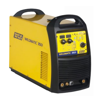
- Page 1 ® Weldmatic 350i + Weldmatic 500i Weldmatic 350i Weldmatic 500i Multiprocess welder Multiprocess welder Model No. CP139-2 Model No. CP140-2 Iss A Iss A Operators Manual 01/16 CP139-40 Rev A...
- Page 2 Welding Industries of Australia A division of ITW Australia Pty Ltd 1300 300 884 Info@welding.com.au welding.com.au...
-
Page 3: Table Of Contents
Weldmatic 350i + Weldmatic 500i Contents Section General Information Page Safe Practices Introduction Receiving Specifications Controls Installation Normal Welding Sequence Basic Welding Information General Maintenance External Trouble Shooting Service Information 10.1 Circuit Diagram Assembly and Parts Lists Warranty information Model No CP139, CP140... -
Page 4: Safe Practices
Operators Manual Safe Practices When Using Read First Welding Equipment The information contained in this These notes are provided in the interests manual is set out to enable you of improving operator safety. They should to properly maintain your new be considered only as a basic guide to Safe equipment and ensure that you obtain Working Habits. -
Page 5: Fire And Explosion Prevention
Weldmatic 350i + Weldmatic 500i Burn Protection coating is removed from the work surface, the area is well ventilated, or the operator The welding arc is intense and visibly bright. wears an air-supplied respirator. Its radiation can damage eyes, penetrate Work in a confined space only while it is light-weight clothing, reflect from light- being ventilated and, if necessary, while... - Page 6 Due to variation between generators by different manufacturers, it is impossible Hollow castings or containers must be vented for WIA to validate operation from all before welding or cutting. They can explode. generators. Therefore, we recommend Never weld or cut where the air may contain that operation of equipment on flammable dust, gas, or liquid vapours.
-
Page 7: Introduction
WIA supplies a wide range of mild steel and steel to aluminium alloys. special purpose electrodes which cater for home workshop, rural, and industrial requirements. -
Page 8: Receiving
Operators Manual 2 Receiving Austarc 16TC, Classification E4916-A Check the equipment received against the shipping invoice to make sure the shipment A low hydrogen electrode with good is complete and undamaged. If any damage arc stability and out-of-position welding has occurred in transit, please immediately characteristics. -
Page 9: Specifications
Weldmatic 350i + Weldmatic 500i 3 Specifications 350i 500i Manufactured to Standards AS60974.1 IEC60974.10 AS60974.1 IEC60974.10 Rated Input Voltage 380 – 415V 3 Phase 380 – 415V 3 Phase Power Frequency 50/60 Hz 50/60 Hz Generator Three Phase Capacity 15KVA 25KVA Rated Maximum Supply Current Imax... -
Page 10: Controls
Operators Manual 4 Controls WELD AMPS WELD VOLTS 31.5 27.6 60% 100% CORED WIRE: - Self Shielded - Gas Shielded - All Sizes LOCAL REMOTE AMPS ARC FORCE AMPS VOLTS 350i WELDMATIC Fig 1 Weldmatic 350i + 500i Controls 1 Control Panel 8 Over Temperature Warning If an over temperature condition is reached 2 Remote Connector... -
Page 11: Mode Selection Button
Weldmatic 350i + Weldmatic 500i 13.4 TIG GTAW welding, LOCAL control: 11 Digital Display Volts Lift arc start, using TIG welding torch with MIG Mode (GMAW): the display will separate gas supply. indicate Actual weld volts. Knob (10) will adjust the weld current which Stick Mode (MMA): the display will indicate is displayed on (9). -
Page 12: Installation
Operators Manual 5 Installation CO2: Is a cheaper gas option for steel when Connection to Electrical Mains Power weld spatter and finish is not a concern. Supply Note: All electrical work shall only be 16 Arc Control undertaken by a qualified electrician. When in MIG GMAW mode the harshness 350i of the arc can be adjusted. - Page 13 Weldmatic 350i + Weldmatic 500i To setup for this condition, connect the The minimum recommended supply circuit ‘WORK’ lead plug into the (-) output terminal breaker rating for a Weldmatic 500i is 32 on the power source, and the wirefeeder Amps.
-
Page 14: Normal Welding Sequence
In draft-free conditions the gas flow rate recommend quality WIA AUSTMIG ES6. required to give adequate protection is Dirty, rusty or kinked wire will not feed typically 10-12 litres/min. In situations where... - Page 15 Weldmatic 350i + Weldmatic 500i Establishing a Weld Setting A “good” weld will have the characteristics illustrated in Figure 2. The weld has penetrated Once the consumable wire type, wire size into the parent metal, fusing the root of the and shielding gas have been chosen, the two joint where the two plates meet, and the weld variables that are adjusted in order to obtain...
- Page 16 Operators Manual Gun Position For “down hand” fillet welding with gas shielded solid wires, the gun is normally positioned as shown in Figure 4a below, with the nozzle end pointing in the direction of travel. For “down hand” fillet welding with gasless flux cored wires, the gun is normally positioned as shown in Figure 4b, with the nozzle end pointing away from the direction...
- Page 17 130 - 180 Select an appropriate welding current for the electrode diameter by setting the knob on the machine front panel. WIA AUSTARC Stick Remote Mode electrodes will give the best results. When in stick remote Mode, the output can...
- Page 18 Operators Manual TIG Welding (GTAW) TIG Welding Operation Connect the Work Clamp to the work piece. Connection for TIG Welding Turn on the power switch located on the rear For TIG welding, the torch is connected to panel. Wait approximately 5 seconds as the the negative terminal.
-
Page 19: Duty Cycle
Weldmatic 350i + Weldmatic 500i LIFT TIG Operation Duty Cycle LIFT TIG arc start can be achieved with the The term duty cycle indicates the percentage following procedure. welding time available at the rated output current, for each 10 min period over 4 hours. The Weldmatic 350i is rated at 350 Amps, and the 500i at 500 Amps, 60% duty cycle. -
Page 20: General Maintenance
Operators Manual 8 General Maintenance 3 Welding tip is free of obstructions such Before removing the equipment as spatter build-up. Ream out the tip cover, ENSURE that the equipment bore with a suitable size oxy-tip cleaner. is disconnected from the mains Replace the welding tip as it becomes power supply. -
Page 21: External Trouble Shooting
WIA service agent. the fault condition, the equipment Power source has low weld output should be returned to a WIA Service agent. Phone 1300 300 884 for details 1 Check all electrical connections in the of your nearest service agent. -
Page 22: Service Information
Operators Manual 10 Service Information 3 Check that gun cable liner is not too The following information is intended short and is fitted correctly. Refer for use by qualified service personnel. wirefeeder manual for fitting instructions. When the unit is energised LETHAL Constant poor arc characteristics VOLTAGES are present on the electrical and electronic components. -
Page 23: Circuit Diagram
Weldmatic 350i + Weldmatic 500i 10.1 Circuit Diagrams – Power Source Fig 7 Weldmatic 350i + 500i Circuit Diagram Model No CP139, CP140... -
Page 24: Assembly And Parts Lists
Operators Manual 11.1 Assembly and Parts List - Weldmatic 350i/500i Fig 8 Weldmatic 350i/500i Assembly Trusted by the best... - Page 25 Weldmatic 350i + Weldmatic 500i Item # Part # Description M0071 Handle PAN164 Enclosure L0027 Control Transformer E0084 Input Filter 500i E0083 Input Filter 350i PWA033 PCB Assembly 350i 500i E0085 Thermostat L0028 Toroid Input 350i 500i D0042 Rectifier 3 PH 350i 500i D0041 IGBT CP140 500i D0040...
-
Page 26: Warranty Information
Weldarc MMA Equipment • The relevant defect in materials or 3 Year Warranty Statement workmanship; Welding Industries of Australia (WIA) • The Product not having been altered, warrants to the original retail purchaser tampered with or otherwise dealt with that the Weldmatic welding machine... - Page 27 Weldmatic 350i + Weldmatic 500i Model No CP139, CP140...
- Page 28 Miller Digital Elite Series ™ AUTO-DARKENING HELMETS Inferno P/N - 257217 Joker P/N - 257218 Lucky’s Speed Shop P/N - 257214 Black P/N - 257213 FOUR MODES – WELD, CUT, GRIND & X-MODE Black Lucky’s Speed Shop Joker Inferno • Lens and helmet comply with •...
Need help?
Do you have a question about the weldmatic 350i CP139-2 and is the answer not in the manual?
Questions and answers