
Related Manuals for WIA WELDMATIC 180


Summary of Contents for WIA WELDMATIC 180
- Page 1 MIG & Multi-Process Welder OPERATORS MANUAL | CP141-1 From serial numbers C1412A* WELDING.COM.AU...
- Page 2 WELDING INDUSTRIES AUSTRALIA A Division of ITW Australia Pty Ltd ABN: 63 004 235 063 1300 300 884 Email: info@welding.com.au welding.com.au WELDWELL NEW ZEALAND A Division of ITW New Zealand NZBN: 9 429 039 833 129 GST NO: 080177186 0800 9353 9355 Email: info@weldwell.co.nz weldwell.co.nz...
-
Page 3: Table Of Contents
CONTENTS Section General Information Page Safe Practices Introduction Receiving Specifications Controls Installation Normal Welding Sequence Basic Welding Information General Maintenance External Trouble Shooting Trouble Shooting Chart Service Information 11.1 Circuit Diagram Assembly & Parts Lists 12.1 Power Source 12.2 Wirefeeder 12.3 Gun &... -
Page 4: Safe Practices
Weldmatic 180 | Operator Manual | Model No CP141-1 SAFE PRACTICES WHEN USING WELDING EQUIPMENT READ FIRST The information contained in this These notes are provided in the interests manual is set out to enable you of improving operator safety. They should... - Page 5 Burn Protection Metals coated with or containing materials that emit fumes should not be heated The welding arc is intense and visibly unless coating is removed from the work bright. Its radiation can damage eyes, surface, the area is well ventilated, or the penetrate light-weight clothing, reflect operator wears an air-supplied respirator.
- Page 6 Weldmatic 180 | Operator Manual | Model No CP141-1 Walls touching combustibles on opposite Shock Prevention sides should not be welded on or cut. Walls, Exposed conductors or other bare metal ceilings, and floor near work should be in the welding circuit, or ungrounded protected by heat-resistant covers or shields.
-
Page 7: Introduction
The Weldmatic has been designed to be WIA supplies a wide range of mild steel and used with consumable wires of different special purpose electrodes which cater diameter. The smaller wire sizes are used... -
Page 8: Receiving
Weldmatic 180 | Operator Manual | Model No CP141-1 Austarc 13S, Classification E4313-A 2 RECEIVING A smooth running electrode with a soft arc, Check the equipment received against the particularly suited to light sheetmetal and shipping invoice to make sure the shipment smooth mitre fillet welds. -
Page 9: Specifications
3 SPECIFICATIONS WELDMATIC 180 Manufactured to Standards AS60974.1 IEC60974.10 Rated Input Voltage 220 – 240V Power Frequency 50/60 Hz Generator Single Phase Capacity 11KVA Rated Maximum Supply Current Imax Maximum Effective Supply Current Ieff Output No Load Voltage VRD Safe 13.5V... - Page 10 Weldmatic 180 | Operator Manual | Model No CP141-1 3 SPECIFICATIONS (CONT) WELDMATIC 180 Spool Size ES6 – 1kg & 5kg Supply Plug 10 Amp Dinse Connector/Weld Cable 9mm/16mm Supply Cable 1.5mm 3 Core Heavy Duty PVC Mains Circuit Breaker Rating...
-
Page 11: Controls
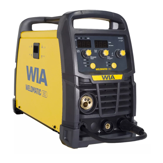
4 CONTROLS Fig 1 Weldmatic 180 Controls Control Panel 8 Power On Indicator 9 Over Temperature Indicator 2 Euro Gun/Cable Connector This light is on if the machine overheats 3 Positive Welding Output Terminal or mains voltage is too high or low – the... - Page 12 Weldmatic 180 | Operator Manual | Model No CP141-1 11 Weld Current & Wire Speed 14 Digital Display – Volts Adjustment Control Knob/Wire During welding actual welding Volts will be INCH Button displayed and then held for 30 seconds after Stick Mode (MMAW) and TIG Mode: the end of the weld.
-
Page 13: Installation
Successful Operation Connection to Electrical Mains Power Supply Successful operation will depend on a number of factors: The Weldmatic 180 is factory fitted with a 3 metre, 3 core 1.5mm Heavy Duty PVC – Variation in circuit breaker thresholds. mains power supply cable with moulded –... - Page 14 Weldmatic 180 | Operator Manual | Model No CP141-1 Negative Wire MIG Welding (GMAW) Some ‘self-shielded’ flux cored gasless Output Voltage Polarity consumable wires are operated with the The design of the Weldmatic allows work piece Positive and the consumable selection of the output voltage polarity.
- Page 15 Fitting the Gas Cylinder Feeding the Consumable Wire At the wirefeed assembly, release the Place the gas cylinder on the tray at the compression screw by swivelling it outwards. rear of the optional welder trolley (if using). This allows the top roller arm to spring to Retain the cylinder with the chain provided.
-
Page 16: Normal Welding Sequence
Weldmatic 180 | Operator Manual | Model No CP141-1 6 NORMAL WELDING SEQUENCE 7 BASIC WELDING INFORMATION Choice of Shielding Gas Weld Start The choice of shielding gas is largely The wire feed has an in built “creep” function. determined by the consumable wire to When the trigger is pressed the wire will be used. - Page 17 Establishing a Weld Setting A “good” weld will have the characteristics illustrated in Figure 4. The weld has Once the consumable wire type, wire size penetrated into the parent metal, fusing and shielding gas have been chosen, the the root of the joint where the two plates two variables that are adjusted in order to meet, and the weld blends smoothly into obtain the desired weld setting are;...
- Page 18 Weldmatic 180 | Operator Manual | Model No CP141-1 WELDMATIC SETTINGS CHART Suggested Settings for Fillet Weld Mild Steel – Gasless Wire Wire Type Stick Out Gasless / Flux Cored Negative Polarity Knurled Drive Roll Arc Control 1 Wire Size 0.8mm...
- Page 19 WELDMATIC SETTINGS CHART (CONT) Suggested Settings for Fillet Weld Mild Steel – Solid Wire Wire Type Carbon Steel ES6 Positive Polarity Gas: Ar + 5% CO + 2% O Arc Control 5 Wire Size 0.6mm 0.8mm Material Wirefeed Volts Wirefeed Volts Thickness 11.0...
- Page 20 Weldmatic 180 | Operator Manual | Model No CP141-1 WELDMATIC SETTINGS CHART (CONT) Suggested Settings for Fillet Weld Mild Steel – Solid Wire Wire Type Carbon Steel ES6 Positive Polarity Gas: Ar + 5% CO Arc Control 5 Wire Size 0.6mm...
- Page 21 Gun Position For “down hand” fillet welding with gas shielded solid wires, the gun is normally positioned as shown in Figure 7a below, with the nozzle end pointing in the direction of travel. For “down hand” fillet welding with gasless flux cored wires, the gun is normally positioned as shown in Figure 7b, with the nozzle end pointing away from the direction...
- Page 22 Weldmatic 180 | Operator Manual | Model No CP141-1 Stick Welding Operation Always fill the crater which tends to form at the end of a weld deposit, by pausing Be certain that you are wearing suitable momentarily before withdrawing the protective clothing, gloves etc and that electrode to break the arc.
- Page 23 TIG Welding Operation LIFT TIG Operation Connect the Work Clamp to the work piece. When the Welding mode is set to LIFT TIG then the arc start can be achieved with the Turn on the power switch located on the following procedure.
- Page 24 Weldmatic 180 | Operator Manual | Model No CP141-1 Duty Cycle The term duty cycle indicates the percentage welding time available at the rated output current, for each 10 min period over 4 hours. The Weldmatic 180 is rated 180 Amps, 10% duty cycle.
-
Page 25: General Maintenance
8 GENERAL MAINTENANCE Welding tip is free of obstructions Before removing the equipment such as spatter build-up. Ream out cover, ENSURE that the equipment the tip bore with a suitable size oxy-tip is disconnected from the mains cleaner. Replace the welding tip as it power supply. -
Page 26: External Trouble Shooting
Weldmatic 180 | Operator Manual | Model No CP141-1 9 EXTERNAL TROUBLE SHOOTING If you are in Australia and the following checks do not identify the fault condition, the equipment should be returned to a WIA Service agent. Phone 1300 300 884 for details of your nearest service agent. -
Page 27: Trouble Shooting Chart
10 TROUBLE SHOOTING CHART Problem Likely Reason Outcome All Inverter Multi-Process Models No welding current, no The machine is not turned on If confirmed that the machine display. at both the mains supply and is switched on correctly, the machine power switch. test the same outlet using a known serviceable appliance. - Page 28 Weldmatic 180 | Operator Manual | Model No CP141-1 Problem Likely Reason Outcome MMA/STICK Models In MMAW (Stick), the arc is The technique required The technique to strike difficult to strike. for VRD enabled welding should be reviewed, not as machines is not the same as a ‘strike’...
- Page 29 Problem Likely Reason Outcome Wire feed stutters and arc Torch consumables are Liners and contact tips is erratic. Also, motor turns blocked/partially blocked. are consumable and wear correctly under no load. over time. Rusty MIG Wire. Replace the torch liner and reduce wire feed tension.
-
Page 30: Service Information
Weldmatic 180 | Operator Manual | Model No CP141-1 11 SERVICE INFORMATION The following information is intended for use by qualified service personnel. The unit is energised, LETHAL VOLTAGES are present on the electrical and electronic components. It is not... -
Page 31: Circuit Diagram
11.1 CIRCUIT DIAGRAMS – POWER SOURCE Fig 12 Weldmatic 180 Circuit Diagram... -
Page 32: Power Source
Weldmatic 180 | Operator Manual | Model No CP141-1 12.1 ASSEMBLY AND PARTS LIST - WELDMATIC 180 POWER SOURCE... - Page 33 Item # Part # Description M0109 Handle PAN180 Outer Cover PAN181 Side Door M0133 Hinge PWA095 EMC Filter board PWA075 Wirefeed Control Board M0121 Front Panel Plastic PWA073 Front Panel Control PCB WIN665 Front Panel Sticker M0104 Knob M0105 Button AM364 Polarity conversion cable SA140-0/2...
- Page 34 Weldmatic 180 | Operator Manual | Model No CP141-1 12.2 ASSEMBLY AND PARTS LIST - WIREFEEDER 180 Fig 15 Wirefeed Assembly Item # Part # Description W27-0/9 Retaining Screw Feed Rolls Item # Part # Description W26-0/8 0.6 + 0.8mm, Solid Wire W26-8/8 0.8 + 0.9mm, Solid Wire...
-
Page 35: Wirefeeder
Tips Wire diameter Short series (25mm) 0.6mm BE7497 0.8mm BE7488 0.9mm BE7489 1.0mm BE7496 1.2mm BE7490 To replace liner: Disconnect gun/cable assembly at the Euro adaptor. Remove nozzle (1) and head (3). Withdraw old liner from the wirefeeder end. Insert new liner and refit gun/cable assembly to the wirefeeder. -
Page 36: Gun & Cable
Weldmatic 180 | Operator Manual | Model No CP141-1 12.3 ASSEMBLY AND PARTS LIST - GUN AND CABLE ASSEMBLY Item # Part # Description BE4392 Brass Nozzle 1/2” BE7488 Contact Tip 0.030”/0.8mm BE7489 Contact Tip 0.035”/0.9mm BE4335 Gas Diffuse BE7126 O-Ring 12.5x1.8... -
Page 37: Australian Warranty Information
This warranty covers the Weldmatic power Effective 1st January 2022 source and wirefeeder only, and does not Welding Industries of Australia (WIA) extend to the regulator, gun assembly warrants to the original retail purchaser that or accessories included in the original the Weldmatic welding machine purchased purchase package. - Page 38 Weldmatic 180 | Operator Manual | Model No CP141-1 Our goods come with guarantees that cannot be excluded under the Australian Consumer Law. You are entitled to a replacement or refund for a major failure and for compensation for any other reasonably foreseeable loss or damage.
-
Page 39: New Zealand Warranty Information
WIA Weldmatic MIG & Weldarc MMA Equipment 3 Year Gold Shield Warranty Statement Effective 1st January 2022 WIA Weldmatic MIG & Weldarc Equipment purchased in New Zealand have identical warranty conditions as Australia, with the below conditions: In the event of defects listed in the... - Page 40 WELDING INDUSTRIES WELDWELL AUSTRALIA NEW ZEALAND A Division of ITW Australia Pty Ltd A Division of ITW New Zealand ABN: 63 004 235 063 NZBN: 9 429 039 833 129 GST NO: 080 177 186 1300 300 884 Email: info@welding.com.au 0800 9353 9355 welding.com.au Email: info@weldwell.co.nz...
Need help?
Do you have a question about the WELDMATIC 180 and is the answer not in the manual?
Questions and answers