
Related Manuals for WIA WELDMATIC 200


Summary of Contents for WIA WELDMATIC 200
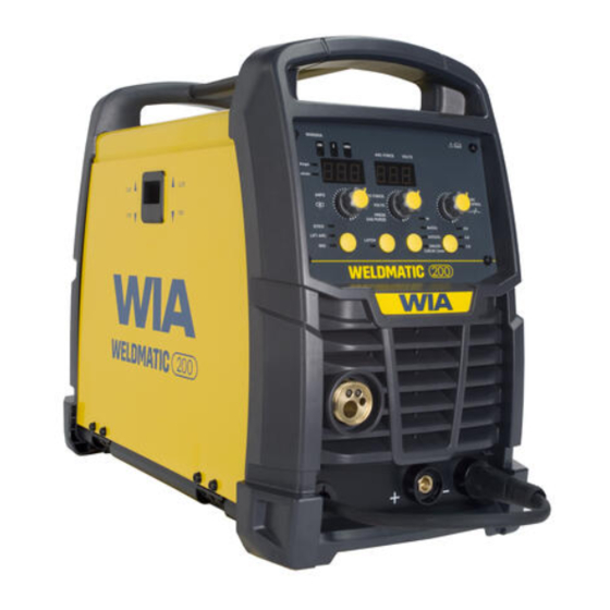
- Page 1 MIG & Multi-Process Welder OPERATORS MANUAL | CP150-1 From serial numbers C1502A* WELDING.COM.AU...
- Page 2 WELDING INDUSTRIES AUSTRALIA A Division of ITW Australia Pty Ltd ABN: 63 004 235 063 1300 300 884 Email: info@welding.com.au welding.com.au WELDWELL NEW ZEALAND A Division of ITW New Zealand NZBN: 9 429 039 833 129 GST NO: 080177186 0800 9353 9355 Email: info@weldwell.co.nz weldwell.co.nz...
-
Page 3: Table Of Contents
CONTENTS Section General Information Page Safe Practices Introduction Receiving Specifications Controls Installation Normal Welding Sequence Basic Welding Information General Maintenance External Trouble Shooting Trouble Shooting Chart Service Information 11.1 Circuit Diagram Assembly & Parts Lists 12.1 Power Source 12.2 Wirefeeder 12.3 Gun &... -
Page 4: Safe Practices
Weldmatic 200 | Operator Manual | Model No CP150-1 SAFE PRACTICES WHEN USING WELDING EQUIPMENT READ FIRST The information contained in this These notes are provided in the interests manual is set out to enable you of improving operator safety. They should... - Page 5 Burn Protection Metals coated with or containing materials that emit fumes should not be heated The welding arc is intense and visibly bright. unless coating is removed from the work Its radiation can damage eyes, penetrate surface, the area is well ventilated, or the light-weight clothing, reflect from light- operator wears an air-supplied respirator.
- Page 6 Weldmatic 200 | Operator Manual | Model No CP150-1 Walls touching combustibles on opposite Shock Prevention sides should not be welded on or cut. Walls, Exposed conductors or other bare metal ceilings, and floor near work should be in the welding circuit, or ungrounded protected by heat-resistant covers or shields.
-
Page 7: Introduction
“self shielded” wires, coating of the electrode. by gases generated by the wire core. The Weldmatic 200 has been designed to The process is very versatile in that by be used with 2.0mm, 2.5mm, 3.2mm and selection of the correct wire composition, 4.0mm diameter electrodes. - Page 8 Weldmatic 200 | Operator Manual | Model No CP150-1 Austarc 13S, Classification E4313-A GTAW (TIG Welding) Gas Tungsten Arc Welding (GTAW) is a A smooth running electrode with a soft arc, welding process where the arc is struck particularly suited to light sheetmetal and between a non-consumable tungsten smooth mitre fillet welds.
-
Page 9: Receiving
If any damage has occurred in transit, please immediately notify your supplier. The Weldmatic 200 package contains: – Weldmatic 200 Power Source – Euro MIG Gun and Cable Assembly –... -
Page 10: Specifications
Weldmatic 200 | Operator Manual | Model No CP150-1 3 SPECIFICATIONS WELDMATIC 200 Manufactured to Standards AS60974.1 IEC60974.10 Rated Input Voltage 220 – 240V Power Frequency 50/60 Hz Generator Single Phase Capacity 13KVA Rated Maximum Supply Current Imax Maximum Effective Supply Current Ieff... - Page 11 3 SPECIFICATIONS (CONT) WELDMATIC 200 Spool Size ES6 – 1kg & 5kg Supply Plug 15Amp Supply Cable 2.5mm2 3 Core Heavy Duty PVC Mains Circuit Breaker Rating Wire Speed Range 2-14.5 Metre/min Wire Size (Solid) 0.6mm-0.9mm Wire Size (Cored) 0.8-1.2mm...
-
Page 12: Controls
Weldmatic 200 | Operator Manual | Model No CP150-1 4 CONTROLS WIN699A Fig 1 Weldmatic 200 Controls 稿制作; :1图样,颜色要求按提供色号为准; Control Panel 6 VRD Safe Indicator 线裁切; PANTONE 432 C 刷以电子稿为准; This light is on when the machine is in Stick 2 m/min Indicator 寸公差按:GB/T1804-m执行。... - Page 13 11 Arc Control 8 Digital Display – Amps or m/min During welding actual welding Amps will When in MIG (GMAW) mode the harshness be displayed and then held for 30 seconds of the arc can be adjusted. after the end of the weld. For example aluminium welding would Stick Mode (MMAW) or TIG Mode require a different setting to steel welding.
-
Page 14: Installation
Weldmatic 200 | Operator Manual | Model No CP150-1 5 INSTALLATION Successful Operation Connection to Electrical Mains Power Supply Successful operation will depend on a number of factors: The Weldmatic 200 is factory fitted with a 3 metre, 3 core 2.5mm Heavy Duty PVC –... - Page 15 MIG Welding (GMAW) Negative Wire Some ‘self-shielded’ flux cored gasless Output Voltage Polarity consumable wires are operated with the work piece Positive and the consumable The design of the Weldmatic allows wire Negative. Refer to the manufacturers selection of the output voltage polarity. data for the particular consumable wire to be used.
- Page 16 Weldmatic 200 | Operator Manual | Model No CP150-1 Fitting the Gas Cylinder Feeding the Consumable Wire Place the gas cylinder on the tray at the At the wirefeed assembly, release the rear of the optional welder trolley (if using).
-
Page 17: Normal Welding Sequence
The recommended shielding gases for use with the Weldmatic 200 are: Closing the welding gun switch initiates this – Mild Steel : Argon + 18% Oxygen ;... - Page 18 Weldmatic 200 | Operator Manual | Model No CP150-1 Establishing a Weld Setting A “good” weld will have the characteristics illustrated in Figure 4. The weld has penetrated Once the consumable wire type, wire size into the parent metal, fusing the root of the...
- Page 19 WELDMATIC SETTINGS CHART Suggested Settings for Fillet Weld Mild Steel – Gasless Wire Wire Type Stick Out Gasless / Flux Cored Negative Polarity Knurled Drive Roll Arc Control 1 Wire Size 0.8mm 0.9mm 1.2mm Stick Stick Stick Material Wirefeed Volts Wirefeed Volts Wirefeed Volts Thickness...
- Page 20 Weldmatic 200 | Operator Manual | Model No CP150-1 WELDMATIC SETTINGS CHART (CONT) Suggested Settings for Fillet Weld Mild Steel – Solid Wire Wire Type Carbon Steel ES6 Positive Polarity Gas: Ar + 5% CO2 + 2% O2 Arc Control 5 Wire Size 0.6mm...
- Page 21 WELDMATIC SETTINGS CHART (CONT) Suggested Settings for Fillet Weld Mild Steel – Solid Wire Wire Type Carbon Steel ES6 Positive Polarity Gas: Ar + 18% CO2 Arc Control 5 Wire Size 0.6mm 0.8mm 0.9mm Material Wirefeed Volts Wirefeed Volts Wirefeed Volts Thickness 10.0...
- Page 22 Weldmatic 200 | Operator Manual | Model No CP150-1 Gun Position For “down hand” fillet welding with gas shielded solid wires, the gun is normally positioned as shown in Figure 7a below, with the nozzle end pointing in the direction of travel.
- Page 23 Select an appropriate welding current for the electrode diameter by setting the knob Connection for TIG Welding on the machine front panel. WIA AUSTARC For TIG welding, the torch is connected to electrodes will give the best results. the negative terminal. Figure 9 illustrates...
- Page 24 Weldmatic 200 | Operator Manual | Model No CP150-1 TIG Welding Operation LIFT TIG Operation Connect the Work Clamp to the work piece. When the Welding mode is set to LIFT TIG then the arc start can be achieved with the Turn on the power switch located on the rear following procedure.
- Page 25 10 min period over 4 hours. The Weldmatic 200 is rated 200 Amps, 15% duty cycle. If the machine is operated at a reduced welding current, a higher duty cycle is available. The diagram below...
-
Page 26: General Maintenance
Weldmatic 200 | Operator Manual | Model No CP150-1 8 GENERAL MAINTENANCE Welding tip is free of obstructions Before removing the equipment such as spatter build-up. Ream out cover, ENSURE that the equipment the tip bore with a suitable size oxy-tip is disconnected from the mains cleaner. -
Page 27: External Trouble Shooting
If you are in Australia and the following checks do not identify the fault condition, the equipment should be returned to a WIA Service agent. Phone 1300 300 884 for details of your nearest service agent. If you are in New Zealand and the... -
Page 28: Trouble Shooting Chart
Weldmatic 200 | Operator Manual | Model No CP150-1 10 TROUBLE SHOOTING CHART Problem Likely Reason Outcome All Inverter Multi-Process Models No welding current, The machine is not turned on If confirmed that the machine no display. at both the mains supply and is switched on correctly, the machine power switch. - Page 29 Problem Likely Reason Outcome MMA/STICK Models In MMAW (Stick), the arc is The technique required The technique to strike difficult to strike. for VRD enabled welding should be reviewed, not as machines is not the same as a ‘strike’ but more as ‘touch, earlier stick welding units.
- Page 30 Weldmatic 200 | Operator Manual | Model No CP150-1 Problem Likely Reason Outcome GMAW/MIG Models (cont.) Wire feed stutters and Torch consumables are Liners and contact tips arc is erratic. Also, motor blocked/partially blocked. are consumable and wear turns correctly under over time.
-
Page 31: Service Information
11 SERVICE INFORMATION The following information is intended for use by qualified service personnel. a the unit is energised LETHAL VOLTAGES are present on the electrical and electronic components. It is not intended that persons without suitable training and knowledge attempt to perform service tasks on the components of this welder. -
Page 32: Circuit Diagram
Weldmatic 200 | Operator Manual | Model No CP150-1 11.1 CIRCUIT DIAGRAMS – POWER SOURCE Fig 11 Weldmatic 200 Circuit Diagram... -
Page 33: Power Source
12.1 ASSEMBLY AND PARTS LIST - WELDMATIC 200 POWER SOURCE Fig 12 Weldmatic 200 Assembly and Parts List... - Page 34 Weldmatic 200 | Operator Manual | Model No CP150-1 Item # Part # Description PAN198 Outer Cover M0109 Handle M0137 Rear Panel E0041 Gas Valve E0078 Main Switch FAN011 PWA112 Main Control Panel PCB PWA113 Wirefeeder Control PCB M0138 Front Panel...
- Page 35 12.2 ASSEMBLY AND PARTS LIST - WIREFEEDER 200 Fig 13 Wirefeed Assembly Item # Part # Description W27-0/9 Retaining Screw Feed Rolls Item # Part # Description W26-0/8 0.6 + 0.8mm, Solid Wire W26-8/8 0.8 + 0.9mm, Solid Wire W26-7/8 1.0//1.2mm, Flux Cored Wire (knurled) W26-9/8 0.9//1.2mm, Flux Cored Wire (knurled)
-
Page 36: Gun & Cable
Weldmatic 200 | Operator Manual | Model No CP150-1 12.3 ASSEMBLY AND PARTS LIST - GUN AND CABLE ASSEMBLY Fig 14 GUN001 (200 amp) Gun and Cable Assembly Item # Part # Description BE4392 Nozzle, Brass, Tapered see 'TIPS' page 37... -
Page 37: Wirefeeder
Tips Wire diameter Short series (25mm) 0.6mm BE7497 0.8mm BE7488 0.9mm BE7489 1.0mm BE7496 1.2mm BE7490 To replace liner: Disconnect gun/cable assembly at the Euro adaptor. Remove nozzle (1) and head (3). Withdraw old liner from the wirefeeder end. Insert new liner and refit gun/cable assembly to the wirefeeder. -
Page 38: Australian Warranty Information
Weldmatic 200 | Operator Manual | Model No CP150-1 13 AUSTRALIAN WARRANTY INFORMATION Any handling and transportation costs (and other expenses) incurred in claiming under this warranty are not covered by this warranty and will not be borne by Welding Industries of Australia. - Page 39 Our goods come with guarantees that cannot be excluded under the Australian Consumer Law. You are entitled to a replacement or refund for a major failure and for compensation for any other reasonably foreseeable loss or damage. You are also entitled to have the goods repaired or replaced if the goods fail to be of acceptable quality and the failure does not amount to a major failure.
-
Page 40: New Zealand Warranty Information
Weldmatic 200 | Operator Manual | Model No CP150-1 14 NEW ZEALAND WARRANTY INFORMATION WIA Weldmatic MIG & Weldarc MMA Equipment 3 Year Gold Shield Warranty Statement Effective 1st January 2022 WIA Weldmatic MIG & Weldarc Equipment purchased in New Zealand have identical... - Page 41 NOTES:...
- Page 42 Weldmatic 200 | Operator Manual | Model No CP150-1 NOTES:...
- Page 43 NOTES:...
- Page 44 WELDING INDUSTRIES WELDWELL AUSTRALIA NEW ZEALAND A Division of ITW Australia Pty Ltd A Division of ITW New Zealand ABN: 63 004 235 063 NZBN: 9 429 039 833 129 GST NO: 080 177 186 1300 300 884 Email: info@welding.com.au 0800 9353 9355 welding.com.au Email: info@weldwell.co.nz...
Need help?
Do you have a question about the WELDMATIC 200 and is the answer not in the manual?
Questions and answers