
Related Manuals for WIA WELDMATIC 356


Summary of Contents for WIA WELDMATIC 356
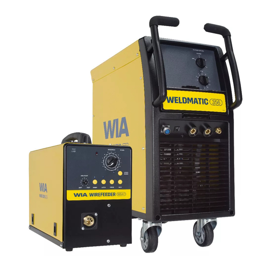
- Page 1 MIG Welder OPERATORS MANUAL | CP147-1, CP148-1 From serial numbers C1472A*, C1482A* WELDING.COM.AU...
- Page 2 WELDING INDUSTRIES AUSTRALIA A Division of ITW Australia Pty Ltd ABN: 63 004 235 063 1300 300 884 Email: info@welding.com.au welding.com.au WELDWELL NEW ZEALAND A Division of ITW New Zealand NZBN: 9 429 039 833 129 GST NO: 080177186 0800 9353 9355 Email: info@weldwell.co.nz weldwell.co.nz...
-
Page 3: Table Of Contents
CONTENTS Section General Information Page Safe Practices Introduction Receiving Specifications Controls Installation Normal Welding Sequence Basic Welding Information General Maintenance External Trouble Shooting Trouble Shooting Chart Circuit Diagram Assembly & Parts Lists Australian Warranty Information New Zealand Warranty Information... -
Page 4: Safe Practices
Weldmatic 356 & 396 | Operator Manual | Model No CP147-2, CP148-2 SAFE PRACTICES WHEN USING WELDING EQUIPMENT READ FIRST These notes are provided in the interests The information contained in this of improving operator safety. They should manual is set out to enable you... - Page 5 Burn Protection Metals coated with or containing materials that emit fumes should not be heated The welding arc is intense and visibly bright. unless coating is removed from the work Its radiation can damage eyes, penetrate surface, the area is well ventilated, or the light-weight clothing, reflect from light- operator wears an air-supplied respirator.
- Page 6 Weldmatic 356 & 396 | Operator Manual | Model No CP147-2, CP148-2 Walls touching combustibles on opposite Shock Prevention sides should not be welded on or cut. Walls, Exposed conductors or other bare metal ceilings, and floor near work should be in the welding circuit, or ungrounded protected by heat-resistant covers or shields.
-
Page 7: Introduction
The welding arc is struck between the work The Weldmatic 356 package contains; piece and the end of the wire, which melts into the weld pool. The arc and the weld –... -
Page 8: Specifications
Weldmatic 356 & 396 | Operator Manual | Model No CP147-2, CP148-2 3 SPECIFICATIONS WELDMATIC 356 WELDMATIC 396 Manufactured to Standards AS60974-1. AS60974-1. Rated Input Voltage 415 Vac, 50 Hz 415 Vac, 50Hz Rated Primary Current 15 Amps 15 Amps... -
Page 9: Controls
4 POWER SOURCE CONTROLS Fig 1 Power Source Controls 1 Ammeter 3 Coarse Voltage, On/Off Control This meter displays actual welding current This switch provides mains power ON/ during welding operation, and a stored OFF and Coarse adjustment of the output reading for 30 seconds after welding. -
Page 10: Installation
Weldmatic 356 & 396 | Operator Manual | Model No CP147-2, CP148-2 5 INSTALLATION Output Voltage Polarity Connection to Electrical Mains Power Supply The design of the Weldmatic 356 & 396 allows selection of the output voltage polarity. NOTE. All electrical work shall... - Page 11 Power Source, as in Figure 3. Remote Wirefeeder The remote wirefeeder is connected to the Weldmatic 356 & 396 power source via the composite cable interconnecting lead. Check all connections are firmly made to ensure good electrical contact, and to prevent gas leaks.
-
Page 12: Normal Welding Sequence
Weldmatic 356 & 396 | Operator Manual | Model No CP147-2, CP148-2 6 NORMAL WELDING SEQUENCE 7 BASIC WELDING INFORMATION Choice of Shielding Gas Weld Start The choice of shielding gas is largely Closing the welding gun switch initiates this... - Page 13 Establishing a Weld Setting Once the consumable wire type, wire size and shielding gas have been chosen, the two variables that are adjusted in order to obtain a the desired weld setting are; – Wirefeed speed, – Welding arc voltage. The wirefeed speed determines the welding current;...
-
Page 14: General Maintenance
Weldmatic 356 & 396 | Operator Manual | Model No CP147-2, CP148-2 8 GENERAL MAINTENANCE Gun Position Before removing the power For “down hand” fillet welding, the gun is source covers, ENSURE that the normally positioned as shown in Figure 6... -
Page 15: External Trouble Shooting
Australian service agents can be to a WIA Service agent. Phone located on the welding.com.au 1300 300 884 for details of your website. nearest service agent. -
Page 16: Trouble Shooting Chart
Weldmatic 356 & 396 | Operator Manual | Model No CP147-2, CP148-2 10 TROUBLE SHOOTING CHART Problem Likely Reason Outcome All Transformer Models No welding current, no The machine is not turned on If confirmed that the machine display. at both the mains supply and is switched on correctly, the machine power switch. - Page 17 Problem Likely Reason Outcome GMAW/MIG Models The machine feeds slowly Creep mode is selected, or Some models have a creep and then speeds up after machine has a permanent mode function that cannot be 3-5 seconds. creep mode function. adjusted. Other models have a push button selection for creep mode on/off.
-
Page 18: Circuit Diagram
Weldmatic 356 & 396 | Operator Manual | Model No CP147-2, CP148-2 11 CIRCUIT DIAGRAMS - POWER SOURCE Fig 7 Power Source Circuit Diagram... -
Page 19: Assembly & Parts Lists
12 ASSEMBLY AND PARTS LIST - WELDMATIC 356 & 396 POWER SOURCE Fig 8 Weldmatic 356 & 396 Power Source Assembly... - Page 20 Weldmatic 356 & 396 | Operator Manual | Model No CP147-2, CP148-2 WELDMATIC 356 & 396 PARTS LIST Item # Part # Description WHL002 Wheel, Rubber, Castor PAN094 Base Panel WHL003 Wheel, Rubber, Fixed E0053 Control Socket MZ231554 Handle Left...
- Page 21 12.1 ASSEMBLY AND PARTS LIST - QTB TORCH Fig 9 350 Amp Gun and Cable Assembly Item # Part # Description see ‘Nozzles’ (page 22) Nozzle see ‘Tips’ (page 22) Contact Tip BED-1 Gas Diffuser, Large BE10012 Insulator BEQT3-45 Body Tube 3”x 45 °...
- Page 22 Weldmatic 356 & 396 | Operator Manual | Model No CP147-2, CP148-2 Nozzles To replace liner: Disconnect gun/cable assembly at the Euro adaptor. Remove nozzle (1) gas diffuser (3) and insulator (4). Part # Description Withdraw old liner from the wirefeeder BEN-3400C Nozzle, copper, 3/4”...
-
Page 23: Australian Warranty Information
Effective 1st January 2022 This warranty covers the Weldmatic power source and wirefeeder only, and does not Welding Industries of Australia (WIA) extend to the regulator, gun assembly warrants to the original retail purchaser that or accessories included in the original the Weldmatic welding machine purchased purchase package. - Page 24 Weldmatic 356 & 396 | Operator Manual | Model No CP147-2, CP148-2 For products purchased in Australia Our goods come with guarantees that cannot be excluded under the Australian Consumer Law. You are entitled to a replacement or refund for...
-
Page 25: New Zealand Warranty Information
14 NEW ZEALAND WARRANTY INFORMATION WIA Weldmatic MIG Equipment 3 Year Gold Shield Warranty Statement Effective 1st January 2022 WIA Weldmatic MIG Equipment purchased in New Zealand have identical warranty conditions as Australia, with the below conditions: In the event of defects listed in the... - Page 26 Weldmatic 356 & 396 | Operator Manual | Model No CP147-2, CP148-2 NOTES:...
- Page 27 NOTES:...
- Page 28 WELDING INDUSTRIES WELDWELL AUSTRALIA NEW ZEALAND A Division of ITW New Zealand A Division of ITW Australia Pty Ltd NZBN: 9 429 039 833 129 ABN: 63 004 235 063 GST NO: 080 177 186 1300 300 884 Email: info@welding.com.au 0800 9353 9355 welding.com.au Email: info@weldwell.co.nz...
Need help?
Do you have a question about the WELDMATIC 356 and is the answer not in the manual?
Questions and answers