Table of Contents
Advertisement
Quick Links
Advertisement
Table of Contents
Troubleshooting

Related Manuals for WIA CP149-1


Summary of Contents for WIA CP149-1
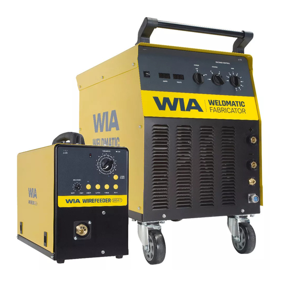
- Page 1 MIG Welder OPERATORS MANUAL | CP149-1 From serial numbers C1492A* WELDING.COM.AU...
- Page 2 WELDING INDUSTRIES AUSTRALIA A Division of ITW Australia Pty Ltd ABN: 63 004 235 063 1300 300 884 Email: info@welding.com.au welding.com.au WELDWELL NEW ZEALAND A Division of ITW New Zealand NZBN: 9 429 039 833 129 GST NO: 080177186 0800 9353 9355 Email: info@weldwell.co.nz weldwell.co.nz...
-
Page 3: Table Of Contents
CONTENTS Section General Information Page Safe Practices Introduction Receiving Specifications Controls Installation Normal Welding Sequence Basic Welding Information General Maintenance External Trouble Shooting Trouble Shooting Chart Service Information Circuit Diagrams Power Source Assembly and Parts List Welding Torch Assembly and Parts List Australian Warranty Information New Zealand Warranty... -
Page 4: Safe Practices
Weldmatic Fabricator | Operator Manual | Model No CP149-2 SAFE PRACTICES WHEN USING WELDING EQUIPMENT READ FIRST These notes are provided in the interests The information contained in this of improving operator safety. They should manual is set out to enable you be considered only as a basic guide to to properly maintain your new Safe Working Habits. - Page 5 Burn Protection surface, the area is well ventilated, or the operator wears an air-supplied respirator. The welding arc is intense and visibly bright. Its radiation can damage eyes, penetrate Work in a confined space only while it is light-weight clothing, reflect from light- being ventilated and, if necessary, while coloured surfaces, and burn the skin and wearing air-supplied respirator.
- Page 6 Weldmatic Fabricator | Operator Manual | Model No CP149-2 Walls touching combustibles on opposite Shock Prevention sides should not be welded on or cut. Exposed conductors or other bare metal Walls, ceilings, and floor near work should in the welding circuit, or ungrounded be protected by heat-resistant covers or electrically alive equipment can fatally shields.
-
Page 7: Introduction
The welding arc is struck between the work The Weldmatic Fabricator Package piece and the end of the wire, which melts CP149-1 contains: into the weld pool. The arc and the weld pool are both shielded by gas flow from the –... -
Page 8: Specifications
Weldmatic Fabricator | Operator Manual | Model No CP149-2 3 SPECIFICATIONS 415 VAC 380 VAC Manufactured to Standards AS60974-1. AS60974-1. Rated Input Voltage 415 Vac, 50 Hz 380 Vac, 50Hz Rated Primary Current 18 Amps 18.5 Amps Maximum Primary Current 27 Amps 24.8 Amps Recommended... -
Page 9: Controls
4 POWER SOURCE CONTROLS Fig 1 Power Source Controls 1 On/Off Control 7 Wirefeeder Control Socket This switch provides mains power ON/OFF Connector for control cable from remote control. wirefeeder. 2 Fine Voltage Control 8 Ammeter This meter displays actual welding current This switch provides Fine adjustment of the output welding voltage over ten steps. -
Page 10: Installation
Weldmatic Fabricator | Operator Manual | Model No CP149-2 5 INSTALLATION Output Voltage Polarity Connection to Electrical Mains Power Supply The design of the Weldmatic Fabricator allows selection of the output voltage NOTE. All electrical work shall polarity. only be undertaken by a qualified electrician. - Page 11 Negative Wire Fitting Eye Bolts Some ‘self-shielded’ flux cored consumable Remove 12mm transport bolts and replace wires are operated with the work piece with supplied eye bolts and fibre washers. Positive and the consumable wire Negative. Centralise the internal nut as the eye bolt is Refer to the manufacturers data for the tightened.
-
Page 12: Normal Welding Sequence
Weldmatic Fabricator | Operator Manual | Model No CP149-2 6 NORMAL WELDING SEQUENCE 7 BASIC WELDING INFORMATION Weld Start Choice of Shielding Gas Closing the welding gun switch initiates this The choice of shielding gas is largely sequence of events: determined by the consumable wire to be used. - Page 13 Establishing a Weld Setting Once the consumable wire type, wire size and shielding gas have been chosen, the two variables that are adjusted in order to obtain the desired weld setting are: – Wirefeed speed, – Welding arc voltage. The wirefeed speed determines the welding current;...
-
Page 14: General Maintenance
Weldmatic Fabricator | Operator Manual | Model No CP149-2 8 GENERAL MAINTENANCE Gun Position Before removing the power For “down hand” fillet welding, the gun is source covers, ENSURE that the normally positioned as shown in Figure 6 equipment is disconnected from below with the nozzle end pointing in the the mains power supply. -
Page 15: External Trouble Shooting
If you are in Australia and the following checks do not identify the fault condition, the equipment should be returned to a WIA Service agent. Phone 1300 300 884 for details of your nearest service agent. If you are in New Zealand and the... -
Page 16: Trouble Shooting Chart
Weldmatic Fabricator | Operator Manual | Model No CP149-2 10 TROUBLE SHOOTING CHART Problem Likely Reason Outcome All Transformer Models No welding current, no The machine is not turned on If confirmed that the machine display. at both the mains supply and is switched on correctly, the machine power switch. - Page 17 Problem Likely Reason Outcome GMAW/MIG Models The machine feeds slowly Creep mode is selected, or Some models have a creep and then speeds up after machine has a permanent mode function that cannot be 3-5 seconds. creep mode function. adjusted. Other models have a push button selection for creep mode on/off.
-
Page 18: Service Information
Weldmatic Fabricator | Operator Manual | Model No CP149-2 11 SERVICE INFORMATION The following information is intended for use by qualified service personnel. The unit is energised, LETHAL VOLTAGES are present on the electrical and electronic components. It is not intended that persons without suitable training and knowledge attempt to perform service tasks... -
Page 19: Circuit Diagrams
12 CIRCUIT DIAGRAMS - POWER SOURCE Fig 7 Power Source Circuit Diagram... -
Page 20: And Parts List
Weldmatic Fabricator | Operator Manual | Model No CP149-2 13 ASSEMBLY AND PARTS LIST - WELDMATIC FABRICATOR POWER SOURCE 20 21 Fig 8 Weldmatic Fabricator Power Source Assembly... - Page 21 Item # Part # Description WHL002 Wheel, Rubber, Castor PAN099 Base Panel WHL005 Wheel, Rubber, Fixed PAN043 Front Panel PAN101 Side Panel (left) E0024 Circuit Breaker, 5 Amp PAN100 Top Panel Not shown M0019 Eye Bolt E0067 Switch, Fine, 10 Position E0066 Switch, Coarse, 3 Position E0068...
- Page 22 Weldmatic Fabricator | Operator Manual | Model No CP149-2 14 ASSEMBLY AND PARTS LIST - TORCH Fig 9 400 Amp Gun and Cable Assembly Item # Part # Description see ‘Nozzles’ (page 23) Nozzle see ‘Tips’ (page 23) Contact Tip BED-1 Gas Diffuser, Large BE10012...
- Page 23 Nozzles To replace liner: Disconnect gun/cable assembly at the Euro adaptor. Remove nozzle (1) gas diffuser (3) and insulator (4). Part # Description Withdraw old liner from the wirefeeder BEN-3400C Nozzle, copper, 3/4” I.D, end. Insert new liner and refit gun/cable flush assembly to the wirefeeder.
-
Page 24: Australian Warranty Information
Effective 1st January 2022 This warranty covers the Weldmatic power source and wirefeeder only, and does not Welding Industries of Australia (WIA) extend to the regulator, gun assembly warrants to the original retail purchaser that or accessories included in the original the Weldmatic welding machine purchased purchase package. - Page 25 For products purchased in Australia Our goods come with guarantees that cannot be excluded under the Australian Consumer Law. You are entitled to a replacement or refund for a major failure and for compensation for any other reasonably foreseeable loss or damage. You are also entitled to have the goods repaired or replaced if the goods fail to be of acceptable quality and the failure does...
-
Page 26: New Zealand Warranty Information
NEW ZEALAND WARRANTY INFORMATION WIA Weldmatic MIG Equipment 3 Year Gold Shield Warranty Statement Effective 1st January 2022 WIA Weldmatic MIG Equipment purchased in New Zealand have identical warranty conditions as Australia, with the below conditions: In the event of defects listed in the... - Page 27 NOTES:...
- Page 28 WELDING INDUSTRIES WELDWELL AUSTRALIA NEW ZEALAND A Division of ITW Australia Pty Ltd A Division of ITW New Zealand ABN: 63 004 235 063 NZBN: 9 429 039 833 129 GST NO: 080177186 1300 300 884 Email: info@welding.com.au 0800 9353 9355 welding.com.au Email: info@weldwell.co.nz weldwell.co.nz...
Need help?
Do you have a question about the CP149-1 and is the answer not in the manual?
Questions and answers