Miller Trailblazer 302 / 275 DC Manual
- Technical manual (81 pages) ,
- Owner's manual (68 pages) ,
- Application manual (16 pages)
Advertisement
- 1 INTRODUCTION
- 2 SAFETY PRECAUTIONS
- 3 DEFINITIONS
- 4 SPECIFICATIONS
-
5
INSTALLATION
- 5.1 Engine Prestart Checks (Kohler-Powered Units)
- 5.2 Engine Prestart Checks (Robin-Powered Units)
- 5.3 Activating The Dry Charge Battery (If Applicable)
- 5.4 Connecting the Battery
- 5.5 Installing Exhaust Pipe
- 5.6 Weld Output Terminals
- 5.7 Connecting To Weld Output Terminals
- 5.8 Selecting Weld Cable Sizes*
- 5.9 Remote Receptacle Information
-
6
OPERATING WELDING GENERATOR
- 6.1 Front Panel Controls
- 6.2 Description Of Front Panel Controls
- 6.3 Cold Weather Engine Operation
- 6.4 Process/Contactor Switch On AC/DC Models
- 6.5 Stick Start Procedure − Scratch Start Technique
- 6.6 TIG Lift-Arc Start Procedure
- 6.7 Ending The TIG Arc With Auto-Crater And Auto-Stop
- 6.8 Remote Voltage/Amperage Control
- 7 OPERATING AUXILIARY EQUIPMENT
-
8
MAINTENANCE
- 8.1 Routine Maintenance
- 8.2 Servicing Optional Spark Arrestor
- 8.3 Servicing Air Cleaner
- 8.4 Changing Engine Oil, Oil Filter, And Fuel Filter (Kohler-Powered Units)
- 8.5 Changing Engine Oil, Oil Filter, and Fuel Filter (Robin-Powered Units)
- 8.6 Adjusting Engine Speed (Kohler-Powered Units)
- 8.7 Adjusting Engine Speed (Robin-Powered Units)
- 8.8 Overload Protection
- 9 Welding Troubleshooting
- 10 Generator Power Troubleshooting
- 11 Engine Troubleshooting
- 12 PARTS LIST
- 13 ELECTRICAL DIAGRAMS
-
14
GENERATOR POWER GUIDELINES
- 14.1 Selecting Equipment
- 14.2 Grounding Generator To Truck Or Trailer Frame
- 14.3 Grounding When Supplying Building Systems
- 14.4 How Much Power Does Equipment Require?
- 14.5 Approximate Power Requirements For Industrial Motors
- 14.6 Approximate Power Requirements For Farm/Home Equipment
- 14.7 Approximate Power Requirements For Contractor Equipment
- 14.8 Power Required To Start Motor
- 14.9 How Much Power Can Generator Supply?
- 14.10 Typical Connections To Supply Standby Power
- 14.11 Selecting Extension Cord (Use Shortest Cord Possible)
- 15 Service & Warranty
- 16 Documents / Resources
INTRODUCTION
From Miller to You
This Owner's Manual is designed to help you get the most out of your Miller products. Please take time to read the Safety precautions. They will help you protect yourself against potential hazards on the worksite. We've made installation and operation quick and easy. With Miller you can count on years of reliable service with proper maintenance. And if for some reason the unit needs repair, there's a Troubleshooting section that will help you figure out what the problem is. The parts list will then help you to decide the exact part you may need to fix the problem. Warranty and service information for your particular model are also provided.
Miller Electric manufactures a full line of welders and welding related equipment. For information on other quality Miller products, contact your local Miller distributor to receive the latest full line catalog or individual specification sheets. To locate your nearest distributor or service agency call 1-800-4-A-Miller, or visit us at www.MillerWelds.com on the web.
SAFETY PRECAUTIONS
READ BEFORE USING

Protect yourself and others from injury — read and follow these precautions.
Symbol Usage
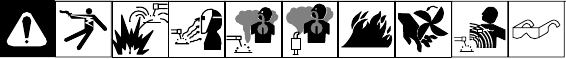
 Means Warning! Watch Out! There are possible hazards with this procedure! The possible hazards are shown in the adjoining symbols.
Marks a special safety message.
 Means "Note"; not safety related.

This group of symbols means Warning! Watch Out! possible ELECTRIC SHOCK, MOVING PARTS, and HOT PARTS hazards. Consult symbols and related instructions below for necessary actions to avoid the hazards.
Arc Welding Hazards
- The symbols shown below are used throughout this manual to call attention to and identify possible hazards. When you see the symbol, watch out, and follow the related instructions to avoid the hazard. The safety information given below is only a summary of the more complete safety information found in the Safety Standards listed in Principal Safety Standards Section. Read and follow all Safety Standards.
- Only qualified persons should install, operate, maintain, and repair this unit.
- During operation, keep everybody, especially children, away.

ELECTRIC SHOCK can kill.
Touching live electrical parts can cause fatal shocks or severe burns. The electrode and work circuit is electrically live whenever the output is on. The input power circuit and machine internal circuits are also live when power is on. In semiautomatic or automatic wire welding, the wire, wire reel, drive roll housing, and all metal parts touching the welding wire are electrically live. Incorrectly installed or improperly grounded equipment is a hazard.
- Do not touch live electrical parts.
- Wear dry, hole-free insulating gloves and body protection.
- Insulate yourself from work and ground using dry insulating mats or covers big enough to prevent any physical contact with the work or ground.
- Do not use AC output in damp areas, if movement is confined, or if there is a danger of falling.
- Use AC output ONLY if required for the welding process.
- If AC output is required, use remote output control if present on unit.
- Additional safety precautions are required when any of the following electrically hazardous conditions are present: in damp locations or while wearing wet clothing; on metal structures such as floors, gratings, or scaffolds; when in cramped positions such as sitting, kneeling, or lying; or when there is a high risk of unavoidable or accidental contact with the workpiece or ground. For these conditions, use the following equipment in order presented:
- semiautomatic DC constant voltage (wire) welder,
- DC manual (stick) welder, or
- an AC welder with reduced open-circuit voltage. In most situations, use of a DC, constant voltage wire welder is recommended. And, do not work alone!
- Disconnect input power or stop engine before installing or servicing this equipment. Lockout/tagout input power according to OSHA 29 CFR 1910.147 (see Safety Standards).
- Properly install and ground this equipment according to its Owner's Manual and national, state, and local codes.
- Always verify the supply ground — check and be sure that input power cord ground wire is properly connected to ground terminal in disconnect box or that cord plug is connected to a properly grounded receptacle outlet.
- When making input connections, attach proper grounding conductor first − double-check connections.
- Frequently inspect input power cord for damage or bare wiring — replace cord immediately if damaged — bare wiring can kill.
- Turn off all equipment when not in use.
- Do not use worn, damaged, undersized, or poorly spliced cables.
- Do not drape cables over your body.
- If earth grounding of the workpiece is required, ground it directly with a separate cable.
- Do not touch electrode if you are in contact with the work, ground, or another electrode from a different machine.
- Use only well-maintained equipment. Repair or replace damaged parts at once. Maintain unit according to manual.
- Do not touch electrode holders connected to two welding machines at the same time since double open-circuit voltage will be present.
- Wear a safety harness if working above floor level.
- Keep all panels and covers securely in place.
- Clamp work cable with good metal-to-metal contact to workpiece or worktable as near the weld as practical.
- Insulate work clamp when not connected to workpiece to prevent contact with any metal object.
- Do not connect more than one electrode or work cable to any single weld output terminal.
SIGNIFICANT DC VOLTAGE exists in inverters after stopping engine.
- Stop engine on inverter and discharge input capacitors according to instructions in Maintenance Section before touching any parts.

FUMES AND GASES can be hazardous.
Welding produces fumes and gases. Breathing these fumes and gases can be hazardous to your health.
- Keep your head out of the fumes. Do not breathe the fumes.
- If inside, ventilate the area and/or use local forced ventilation at the arc to remove welding fumes and gases.
- If ventilation is poor, wear an approved air-supplied respirator.
- Read and understand the Material Safety Data Sheets (MSDSs) and the manufacturer's instructions for metals, consumables, coatings, cleaners, and degreasers.
- Work in a confined space only if it is well ventilated, or while wearing an airsupplied respirator. Always have a trained watchperson nearby. Welding fumes and gases can displace air and lower the oxygen level causing injury or death. Be sure the breathing air is safe.
- Do not weld in locations near degreasing, cleaning, or spraying operations. The heat and rays of the arc can react with vapors to form highly toxic and irritating gases.
- Do not weld on coated metals, such as galvanized, lead, or cadmium plated steel, unless the coating is removed from the weld area, the area is well ventilated, and while wearing an air-supplied respirator. The coatings and any metals containing these elements can give off toxic fumes if welded.

BUILDUP OF GAS can injure or kill.
- Shut off shielding gas supply when not in use.
- Always ventilate confined spaces or use approved air-supplied respirator.

ARC RAYS can burn eyes and skin.
Arc rays from the welding process produce intense visible and invisible (ultraviolet and infrared) rays that can burn eyes and skin. Sparks fly off from the weld.
- Wear an approved welding helmet fitted with a proper shade of filter lenses to protect your face and eyes from arc rays and sparks when welding or watching (see ANSI Z49.1 and Z87.1 listed in Safety Standards).
- Wear approved safety glasses with side shields under your helmet.
- Use protective screens or barriers to protect others from flash, glare, and sparks; warn others not to watch the arc.
- Wear protective clothing made from durable, flame-resistant material (leather, heavy cotton, or wool) and foot protection.

WELDING can cause fire or explosion.
Welding on closed containers, such as tanks, drums, or pipes, can cause them to blow up. Sparks can fly off from the welding arc. The flying sparks, hot workpiece, and hot equipment can cause fires and burns. Accidental contact of electrode to metal objects can cause sparks, explosion, overheating, or fire. Check and be sure the area is safe before doing any welding.
- Remove all flammables within 35 ft (10.7 m) of the welding arc. If this is not possible, tightly cover them with approved covers.
- Do not weld where flying sparks can strike flammable material.
- Protect yourself and others from flying sparks and hot metal.
- Be alert that welding sparks and hot materials from welding can easily go through small cracks and openings to adjacent areas.
- Watch for fire, and keep a fire extinguisher nearby.
- Be aware that welding on a ceiling, floor, bulkhead, or partition can cause fire on the hidden side.
- Do not weld on closed containers such as tanks, drums, or pipes, unless they are properly prepared according to AWS F4.1 (see Safety Standards).
- Connect work cable to the work as close to the welding area as practical to prevent welding current from traveling long, possibly unknown paths and causing electric shock, sparks, and fire hazards.
- Do not use welder to thaw frozen pipes.
- Remove stick electrode from holder or cut off welding wire at contact tip when not in use.
- Wear oil-free protective garments such as leather gloves, heavy shirt, cuffless trousers, high shoes, and a cap.
- Remove any combustibles, such as a butane lighter or matches, from your person before doing any welding.
- Follow requirements in OSHA 1910.252 (a) (2) (iv) and NFPA 51B for hot work and have a fire watcher and extinguisher nearby.

FLYING METAL can injure eyes.
- Welding, chipping, wire brushing, and grinding cause sparks and flying metal. As welds cool, they can throw off slag.
- Wear approved safety glasses with side shields even under your welding helmet.

HOT PARTS can cause severe burns.
- Do not touch hot parts bare handed.
- Allow cooling period before working on equipment.
- To handle hot parts, use proper tools and/or wear heavy, insulated welding gloves and clothing to prevent burns.

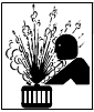
NOISE can damage hearing.
Noise from some processes or equipment can damage hearing.
- Wear approved ear protection if noise level is high.

MAGNETIC FIELDS can affect pacemakers.
- Pacemaker wearers keep away.
- Wearers should consult their doctor before going near arc welding, gouging, or spot welding operations.

CYLINDERS can explode if damaged.
Shielding gas cylinders contain gas under high pressure. If damaged, a cylinder can explode. Since gas cylinders are normally part of the welding process, be sure to treat them carefully.
- Protect compressed gas cylinders from excessive heat, mechanical shocks, physical damage, slag, open flames, sparks, and arcs.
- Install cylinders in an upright position by securing to a stationary support or cylinder rack to prevent falling or tipping.
- Keep cylinders away from any welding or other electrical circuits.
- Never drape a welding torch over a gas cylinder.
- Never allow a welding electrode to touch any cylinder.
- Never weld on a pressurized cylinder — explosion will result.
- Use only correct shielding gas cylinders, regulators, hoses, and fittings designed for the specific application; maintain them and associated parts in good condition.
- Turn face away from valve outlet when opening cylinder valve.
- Keep protective cap in place over valve except when cylinder is in use or connected for use.
- Use the right equipment, correct procedures, and sufficient number of persons to lift and move cylinders.
- Read and follow instructions on compressed gas cylinders, associated equipment, and Compressed Gas Association (CGA) publication P-1 listed in Safety Standards.
Engine Hazards

BATTERY EXPLOSION can BLIND.
- Always wear a face shield, rubber gloves, and protective clothing when working on a battery.
- Stop engine before disconnecting or connecting battery cables or servicing battery.
- Do not allow tools to cause sparks when working on a battery.
- Do not use welder to charge batteries or jump start vehicles.
- Observe correct polarity (+ and −) on batteries.
- Disconnect negative (−) cable first and connect it last.

FUEL can cause fire or explosion.
- Stop engine and let it cool off before checking or adding fuel.
- Do not add fuel while smoking or if unit is near any sparks or open flames.
- Do not overfill tank — allow room for fuel to expand.
- Do not spill fuel. If fuel is spilled, clean up before starting engine.
- Dispose of rags in a fireproof container.
- Always keep nozzle in contact with tank when fueling.

MOVING PARTS can cause injury.
- Keep away from fans, belts, and rotors.
- Keep all doors, panels, covers, and guards closed
- Stop engine before installing or connecting unit.
- Have only qualified people remove doors, panels, covers, or guards for maintenance and troubleshooting as necessary.
- To prevent accidental starting during servicing, disconnect negative (−) battery cable from battery.
- Keep hands, hair, loose clothing, and tools away from moving parts.
- Reinstall doors, panels, covers, or guards when servicing is finished and before starting engine.
- Before working on generator, remove spark plugs or injectors to keep engine from kicking back or starting.
- Block flywheel so that it will not turn while working on generator components.

HOT PARTS can cause severe burns.
- Do not touch hot engine parts.
- Allow cooling period before maintaining.
- Wear protective gloves and clothing when working on a hot engine.
STEAM AND HOT COOLANT can burn.
- If possible, check coolant level when engine is cold to avoid scalding.
- Always check coolant level at overflow tank, if present on unit, instead of radiator (unless told otherwise in maintenance section or engine manual).
- If the engine is warm, checking is needed, and there is no overflow tank, follow the next two statements.
- Wear safety glasses and gloves and put a rag over radiator cap.
- Turn cap slightly and let pressure escape slowly before completely removing cap.

ENGINE EXHAUST GASES can kill.
- Use equipment outside in open, well-ventilated areas.
- If used in a closed area, vent engine exhaust outside and away from any building air intakes.

BATTERY ACID can BURN SKIN and EYES.
- Do not tip battery.
- Replace damaged battery.
- Flush eyes and skin immediately with water.

ENGINE HEAT can cause fire.
- Do not locate unit on, over, or near combustible surfaces or flammables.
- Keep exhaust and exhaust pipes way from flammables.

EXHAUST SPARKS can cause fire.
- Do not let engine exhaust sparks cause fire.
- Use approved engine exhaust spark arrestor in required areas — see applicable codes.
Compressed Air Hazards

BREATHING COMPRESSED AIR can cause serious injury or death.
- Do not use compressed air for breathing.
- Use only for cutting, gouging, and tools.

COMPRESSED AIR can cause injury.
- Wear approved safety goggles.
- Do not direct air stream toward self or others.

TRAPPED AIR PRESSURE AND WHIPPING HOSES can cause injury.
- Release air pressure from tools and system before servicing, adding or changing attachments, or opening compressor oil drain or oil fill cap.
HOT METAL from air arc cutting and gouging can cause fire or explosion.
- Do not cut or gouge near flammables.
- Watch for fire; keep extinguisher nearby.

HOT PARTS can cause burns and injury.
- Do not touch hot compressor or air system parts.
- Let system cool down before touching or servicing.

READ INSTRUCTIONS.
- Read Owner's Manual before using or servicing unit.
- Stop engine and release air pressure before servicing.
- Use only genuine Miller/Hobart replacement parts.
Additional Symbols For Installation, Operation, And Maintenance
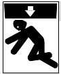
FALLING UNIT can cause injury.
- Use lifting eye to lift unit and properly installed accessories only. Do not exceed maximum lift eye weight rating (see Specifications).
- Lift and support unit only with proper equipment and correct procedures.
- If using lift forks to move unit, be sure forks are long enough to extend beyond opposite side of unit.

OVERHEATING can damage motors.
- Turn off or unplug equipment before starting or stopping engine.
- Do not let low voltage and frequency caused by low engine speed damage electric motors.
- Do not connect 50 or 60 Hertz motors to the 100 Hertz receptacle where applicable.

FLYING SPARKS can cause injury.
- Wear a face shield to protect eyes and face.
- Shape tungsten electrode only on grinder with proper guards in a safe location wearing proper face, hand, and body protection.
- Sparks can cause fires — keep flammables away.

OVERUSE can cause OVERHEATING.
- Allow cooling period; follow rated duty cycle.
- Reduce current or reduce duty cycle before starting to weld again.
- Do not block or filter airflow to unit.
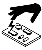
STATIC (ESD) can damage PC boards.
- Put on grounded wrist strap BEFORE handling boards or parts.
- Use proper static-proof bags and boxes to store, move, or ship PC boards.

TILTING OF TRAILER can cause injury.
- Use tongue jack or blocks to support weight.
- Properly install welding generator onto trailer according to instructions supplied with trailer.

READ INSTRUCTIONS.
- Use only genuine MILLER/Hobart replacement parts.
- Perform engine and air compressor (if applicable) maintenance and service according to this manual and the engine/air compressor (if applicable) manuals.
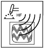
H.F. RADIATION can cause interference.
- High-frequency (H.F.) can interfere with radio navigation, safety services, computers, and communications equipment.
- Have only qualified persons familiar with electronic equipment perform this installation.
- The user is promptly correct any interference problem resulting from the installation. responsible for having a qualified electrician
- If notified by the FCC about interference, stop using the equipment at once.
- Have the installation regularly checked and maintained.
- Keep high-frequency source doors and panels tightly shut, keep spark gaps at correct setting, and use grounding and shielding to minimize the possibility of interference.

ARC WELDING can cause interference.
- Electromagnetic energy can interfere with sensitive electronic equipment such as microprocessors, computers, and computer-driven equipment such as robots.
- Be sure all equipment in the welding area is electromagnetically compatible.
- To reduce possible interference, keep weld cables as short as possible, close together, and down low, such as on the floor.
- Locate welding operation 100 meters from any sensitive electronic equipment.
- Be sure this welding machine is installed and grounded according to this manual.
- If interference still occurs, the user must take extra measures such as moving the welding machine, using shielded cables, using line filters, or shielding the work area.
California Proposition 65 Warnings
- Welding or cutting equipment produces fumes or gases which contain chemicals known to the State of California to cause birth defects and, in some cases, cancer. (California Health & Safety Code Section 25249.5 et seq.)
- Battery posts, terminals and related accessories contain lead and lead compounds, chemicals known to the State of California to cause cancer and birth defects or other reproductive harm. Wash hands after handling.
For Gasoline Engines:
- Engine exhaust contains chemicals known to the State o California to cause cancer, birth defects, or other reproductive harm.
For Diesel Engines:
- Diesel engine exhaust and some of its constituents are known to the State of California to cause cancer, birth defects, and other reproductive harm.
Principal Safety Standards
Safety in Welding, Cutting, and Allied Processes, ANSI Standard Z49.1, from Global Engineering Documents (phone: 1-877-413-5184, website: www.global.ihs.com).
Recommended Safe Practices for the Preparation for Welding and Cutting of Containers and Piping, American Welding Society Standard AWS F4.1, from Global Engineering Documents (phone: 1-877-413-5184, website: www.global.ihs.com).
National Electrical Code, NFPA Standard 70, from National Fire Protection Association, P.O. Box 9101, 1 Battery March Park, Quincy, MA 02269-9101 (phone: 617-770-3000, website: www.nfpa.org and www.sparky.org).
Safe Handling of Compressed Gases in Cylinders, CGA Pamphlet P-1, from Compressed Gas Association, 1735 Jefferson Davis Highway, Suite 1004, Arlington, VA 22202-4102 (phone: 703-412-0900, website: www.cganet.com).
Code for Safety in Welding and Cutting, CSA Standard W117.2, from Canadian Standards Association, Standards Sales, 178 Rexdale Boulevard, Rexdale, Ontario, Canada M9W 1R3 (phone: 800-463-6727 or in Toronto 416-747-4044, website: www.csa-international.org).
Practice For Occupational And Educational Eye And Face Protection, ANSI Standard Z87.1, from American National Standards Institute, 11 West 42nd Street, New York, NY 10036–8002 (phone: 212-642-4900, website: www.ansi.org).
Standard for Fire Prevention During Welding, Cutting, and Other Hot Work, NFPA Standard 51B, from National Fire Protection Association, P.O. Box 9101, 1 Battery March Park, Quincy, MA 02269-9101 (phone: 617-770-3000, website: www.nfpa.org.
OSHA, Occupational Safety and Health Standards for General Industry, Title 29, Code of Federal Regulations (CFR), Part 1910, Subpart Q, and Part 1926, Subpart J, from U.S. Government Printing Office, Superintendent of Documents, P.O. Box 371954, Pittsburgh, PA 15250 (there are 10 Regional Offices—phone for Region 5, Chicago, is 312-353-2220, website: www.osha.gov).
EMF Information
Considerations About Welding And The Effects Of Low Frequency Electric And Magnetic Fields
Welding current, as it flows through welding cables, will cause electromagnetic fields. There has been and still is some concern about such fields. However, after examining more than 500 studies spanning 17 years of research, a special blue ribbon committee of the National Research Council concluded that: "The body of evidence, in the committee's judgment, has not demonstrated that exposure to power frequency electric and magnetic fields is a human-health hazard." However, studies are still going forth and evidence continues to be examined. Until the final conclusions of the research are reached, you may wish to minimize your exposure to electromagnetic fields when welding or cutting.
To reduce magnetic fields in the workplace, use the following procedures:
- Keep cables close together by twisting or taping them.
- Arrange cables to one side and away from the operator.
- Do not coil or drape cables around your body.
- Keep welding power source and cables as far away from operator as practical.
- Connect work clamp to workpiece as close to the weld as possible.
About Pacemakers:
Pacemaker wearers consult your doctor before welding or going near welding operations. If cleared by your doctor, then following the above procedures is recommended.
DEFINITIONS
Symbol Definitions

SPECIFICATIONS
Weld, Power, And Engine Specifications
| Welding Mode | Rated Welding Output | Maximum Open-Circuit Voltage | Weld Output Range | Generator Power Rating | Fuel Capacity | Engine |
| CC/DC | 280 A, 25 V, 100% Duty Cycle | 50 | 20 − 300 A | Continuous: 9.5 kVA/ Continuous: 9.5 kVA/ kW, 80/40 A, 120/240 V AC, 60 Hz, Single-Phase, Peak: 10.5 kVA/kW Peak: 10.5 kVA/kW (w/Weld Contactor Off) | 12 gal (45 L) Tank | Robin EH65 Air-Cooled, Two-Cylinder, Four- Cycle, 22 HP Gasoline Engine or Kohler CH-23 Kohler CH-23 Air-Cooled, Two-Cylinder, Four-Cycle, 23 HP Gasoline Engine |
| CV/DC | 300 A, 25 V, 100% Duty Cycle | 35 | 13 − 35 V | |||
| CC/AC* | 200 A, 25 V, 60% Duty Cycle | 60 | 35 − 225 A |
* AC/DC Models Only.
Dimensions, Weights, and Operating Angles

Fuel Consumption Curves
On a typical job using 1/8 in 7018 electrodes (125 amps, 20% duty cycle), expect about 20 hours of operation. Welding at 150 amps at 40% duty cycle uses approximately 3/4 gallon per hour, or about 16 hours of operation.

Generator Power Curve
The ac generator power curve shows the generator power available in amperes at the receptacles.
Tools and motors are designed to operate within 10% of 120/240 VAC.

Duty Cycle

Stick And MIG Mode Volt-Ampere Curves
The volt-ampere curves show the minimum and maximum voltage and amperage output capabilities of the welding generator. Curves of other settings fall between the curves shown.

TIG Mode Volt-Ampere Curves
The volt-ampere curves show the minimum and maximum voltage and amperage output capabilities of the welding generator. Curves of other settings fall between the curves shown.
AC output is not available on all models.

INSTALLATION
- Do not weld on base. Welding on base can cause fuel tank fire or explosion. Bolt unit down using holes provided in base.
- Always securely fasten welding generator onto transport vehicle or trailer and comply with all DOT and other applicable codes.
- Do not mount unit by supporting the base only at the four mounting holes. Use crosssupports to adequately support unit and prevent damage to base.
- Always ground generator frame to vehicle frame to prevent electric shock and static electricity hazards.
- If unit does not have GFCI receptacles, use GFCI-protected extension cord.
- Do not install unit where air flow is restricted or engine may overheat.

Mounting:

- Cross-Supports Mount unit on flat surface or use cross-supports to support base.
Grounding:

- Equipment Grounding Terminal (On Front Panel)
- Grounding Cable (Not Supplied)
- Metal Vehicle Frame
Connect cable from equipment ground terminal to metal vehicle frame.
Use #10 AWG or larger insulated copper wire.
Engine Prestart Checks (Kohler-Powered Units)
Check all fluids daily. Engine must be cold and on a level surface. Unit is shipped with 10W30 engine oil.
")
Follow run-in procedure in engine manual.
This unit has a low oil pressure shutdown switch. However, some conditions may cause engine damage before the engine shuts down. Check oil level often and do not use the oil pressure shutdown system to monitor oil level.
Open top service door
Fuel
Add fresh fuel before starting engine the first time (see maintenance label for specifications). Always leave filler neck empty to allow room for expansion. Check fuel level on a cold engine before use each day.
To check fuel level, turn Engine Control switch to Run/Idle position. LED's indicate fuel level in tank.
Oil
Do not exceed the "Full" mark on the oil level dipstick. The fuel pump may operate erratically if crankcase is overfilled.
After fueling, check oil with unit on level surface. If oil is not up to full mark on dipstick, add oil (see maintenance label).
Use front panel meters to determine hours until next recommended oil change (see Front Panel Controls Section).
To improve cold weather starting:
- Keep battery in good condition. Store battery in warm area.
- Use correct grade oil for cold weather.
Close top service door
Engine Prestart Checks (Robin-Powered Units)
Check all fluids daily. Engine must be cold and on a level surface. Unit is shipped with 10W30 engine oil.
")
Follow run-in procedure in engine manual.
This unit has a low oil pressure shutdown switch. However, some conditions may cause engine damage before the engine shuts down. Check oil level often and do not use the oil pressure shutdown system to monitor oil level.
Open top service door.
Fuel
Add fresh fuel before starting engine the first time (see maintenance label for specifications). Always leave filler neck empty to allow room for expansion. Check fuel level on a cold engine before use each day.
To check fuel level, turn Engine Control switch to Run/Idle position. LED's indicate fuel level in tank.
Oil
Do not exceed the "Full" mark on the oil level dipstick. The fuel pump may operate erratically if crankcase is overfilled.
After fueling, check oil with unit on level surface. If oil is not up to full mark on dipstick, add oil (see maintenance label).
Use front panel meters to determine hours until next recommended oil change (see Front Panel Controls Section).
To improve cold weather starting:
- Keep battery in good condition. Store battery in warm area.
- Use correct grade oil for cold weather.
Close top service door.
Activating The Dry Charge Battery (If Applicable)
- Always wear a face shield, rubber gloves and protective clothing when working on a battery.
Remove battery from unit.
")
- Vent Caps
- Sulfuric Acid Electrolyte (1.265 Specific Gravity)
- Well
Fill each cell with electrolyte to bottom of well (maximum).
- Do not overfill battery cells.
Wait ten minutes and check electrolyte level. If necessary, add electrolyte to raise to proper level. Reinstall vent caps.
- Battery Charger
- Read and follow all instructions supplied with battery charger.
Charge battery for 12 minutes at 30 amperes or 30 minutes at 5 amperes. Disconnect charging cables and install battery.
When electrolyte is low, add only distilled water to cells to maintain proper level.
Connecting the Battery

Installing Exhaust Pipe
- Stop engine and let cool.
- Engine backfire can cause severe burns or other injuries. Do not point exhaust pipe toward control panel. Keep away from exhaust outlet.
- Do not point exhaust pipe toward LP fuel tank (if equipped). Do not point exhaust pipe towards shielding gas tank (if equipped).
Point exhaust pipe in desired direction but always away from front panel and direction of travel.

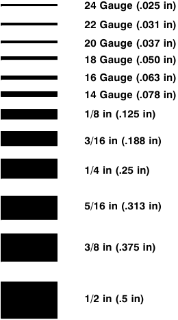
MATERIAL THICKNESS REFERENCE CHART
Weld Output Terminals
- Stop engine.
- Do not connect to CC and CV terminals at the same time.

AC/DC Models:
- Work Weld Output Terminal
- Stick/TIG (CC) Weld Output Terminal
- Wire /CV Weld Output Terminal
For MIG welding, connect work cable to Work terminal and wire feeder cable to Wire (CV) terminal.
For Stick/TIG welding, connect work cable to Work terminal and electrode holder/TIG torch cable to Stick/TIG (CC) terminal.
DC Models:
- Negative (−) Weld Output Terminal
- Stick/TIG (+) Weld Output Terminal
- Wire (+) Weld Output Terminal
For MIG welding, connect work cable to Negative (−) terminal and wire feeder cable to CV (Wire) terminal.
For Stick welding, connect work cable to Negative (−) terminal and electrode holder cable to CC (Stick/ TIG) terminal.
For TIG welding, connect work cable to CC (Stick/TIG) terminal and electrode holder cable to Negative (−) terminal.
Connecting To Weld Output Terminals
- Stop engine.
- Failure to properly connect weld cables may cause excessive heat and start a fire, or damage your machine.

- Weld Output Terminal
- Supplied Weld Output Terminal Nut
- Weld Cable Terminal
- Copper Bar
Remove supplied nut from weld output terminal. Slide weld cable terminal onto weld output terminal and secure with nut so that weld cable terminal is tight against copper bar.
Do not place anything between weld cable terminal and copper bar. Make sure that the surfaces of the weld cable terminal and copper bar are clean.
Selecting Weld Cable Sizes*
 Weld Output Terminals
| Welding Amperes | Weld Cable Size** and Total Cable (Copper) Length in Weld Circuit Not Exceeding*** | |||||||
| 100 ft (30 m) or Less | 150 ft (45 m) | 200 ft (60 m) | 250 ft (70 m) | 300 ft (90 m) | 350 ft (105 m) | 400 ft (120 m) | |||
| 10 − 60% Duty Cycle | 60 − 100% Duty Cycle | 10 − 100% Duty Cycle | |||||||
| 100 | 4 (20) | 4 (20) | 4 (20) | 3 (30) | 2 (35) | 1 (50) | 1/0 (60) | 1/0 (60) | |
| 150 | 3 (30) | 3 (30) | 2 (35) | 1 (50) | 1/0 (60) | 2/0 (70) | 3/0 (95) | 3/0 (95) | |
| 200 | 3 (30) | 2 (35) | 1 (50) | 1/0 (60) | 2/0 (70) | 3/0 (95) | 4/0 (120) | 4/0 (120) | |
| 250 | 2 (35) | 1 (50) | 1/0 (60) | 2/0 (70) | 3/0 (95) | 4/0 (120) | 2 ea. 2/0 (2x70) | 2 ea. 2/0 (2x70) | |
| 300 | 1 (50) | 1/0 (60) | 2/0 (70) | 3/0 (95) | 4/0 (120) | 2 ea. 2/0 (2x70) | 2 ea. 3/0 (2x95) | 2 ea. 3/0 (2x95) | |
| 350 | 1/0 (60) | 2/0 (70) | 3/0 (95) | 4/0 (120) | 2 ea. 2/0 (2x70) | 2 ea. 3/0 (2x95) | 2 ea. 3/0 (2x95) | 2 ea. 4/0 (2x120) | |
| 400 | 1/0 (60) | 2/0 (70) | 3/0 (95) | 4/0 (120) | 2 ea. 2/0 (2x70) | 2 ea. 3/0 (2x95) | 2 ea. 4/0 (2x120) | 2 ea. 4/0 (2x120) | |
* This chart is a general guideline and may not suit all applications. If cables overheat, use next size larger cable.
**Weld cable size (AWG) is based on either a 4 volts or less drop or a current density of at least 300 circular mils per ampere.
( ) = mm2 for metric use
***For distances longer than those shown in this guide, call a factory applications representative at 920-735-4505.
Remote Receptacle Information
NOTE
Engine runs at weld/power speed whenever a device connected to the remote receptacle is running.

*The remaining sockets are not used.
OPERATING WELDING GENERATOR
Front Panel Controls
(See Description Of Front Panel Controls Section )

Description Of Front Panel Controls
(See Front Panel Controls Section)
- Process/Contactor Switch See Process/Contactor Switch On AC/DC Models Section for Process/Contactor switch information.
- Remote Receptacle
Use receptacle to connect remote control or wire feeder. When a remote voltage/amperage control is connected to the Remote receptacle, the Auto Sense Remote feature automatically switches voltage/amperage control to the remote control (see Sections Remote Receptacle Information and Remote Voltage/Amperage Control). With remote voltage/amperage control connected, weld output in CC mode is determined by a combination of front panel and remote control voltage/amperage settings. In CV mode, weld output is controlled through remote control only. If no remote voltage/amperage control is connected to the Remote receptacle, the front panel Voltage/Amperage control adjusts voltage and amperage. - And 4. Displays
Displays can show weld process information (voltage and amperage) or maintenance information (hourmeter, oil change countdown, or rpm).
Meter Weld Functions: In Wire modes, Voltmeter displays preset weld voltage when not welding. Meters display actual voltage and amperage when welding and for five seconds after welding has stopped.
In Stick and TIG modes, Voltmeter reads ON and Ammeter displays preset amperage when not welding. Meters display actual voltage and amperage when welding and for five seconds after welding has stopped.
Meter Engine Maintenance Functions: See inset from maintenance label.
- Fuel Level Indicator With Engine running or Engine Control switch in Run or Run/Idle position, LED's indicate fuel left in tank.
- Voltage/Amperage Control
Use control to select weld voltage or amperage. Control may be adjusted while welding. With Process/Contactor switch in any Stick or TIG setting, use control to adjust amperage.
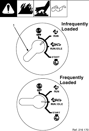
With Process/Contactor switch in any Wire position, use control to adjust voltage. When a remote voltage/amperage control is connected to Remote receptacle RC4, control sets the maximum amperage in Stick and TIG modes, but has no effect in MIG modes. - Engine Control Switch
Use switch to start engine, select speed, and stop engine. In Run/Idle position, engine runs at idle speed at no load, and weld/power speed under load. In Run position, engine runs at weld/power speed. Use switch in combination with meters to determine total engine hours and hours until next recommended oil change (see items 3 and 4 earlier in this section).
![information]() The unit will not return to idle speed when the remote contactor is on and Process/Contactor switch is in any Wire position. The unit will return to idle speed in all other modes.
The unit will not return to idle speed when the remote contactor is on and Process/Contactor switch is in any Wire position. The unit will return to idle speed in all other modes. - Engine Choke Control
Use control to change engine air-fuel mix when starting engine.
To Start: pull out choke and turn Engine Control switch to Start position. Release switch and slowly push choke in when engine starts.
![information]() If the engine does not start, let the engine come to a complete stop before attempting restart.
If the engine does not start, let the engine come to a complete stop before attempting restart.
![information]() During cold weather some gasoline engines encounter difficulties that are easily remedied. See Section Cold Weather Engine Operation and Engine Troubleshooting.
During cold weather some gasoline engines encounter difficulties that are easily remedied. See Section Cold Weather Engine Operation and Engine Troubleshooting.
To Stop: turn Engine Control switch to Off position. - DC Polarity/AC Switch (AC/DC Models Only)
- Do not switch under load.
Use switch to select AC weld output or polarity of DC weld output.
Cold Weather Engine Operation
- Engine Control Switch
Carburetor Icing
Carburetor icing causes the unit to drop below the normal idle speed and then stall. This condition occurs when the temperature is near freezing and the relative humidity is high. Ice forms on the throttle plate and inner bore of the carburetor. The engine typically restarts without problems but soon stalls again.
- Treat gasoline with a fuel de-icer product (isopropyl alcohol).
- Place the Engine Control switch in the Run position.
- Run engine only when expecting to frequently load it.
Breather Icing
Oil breather/pulse line icing occurs in severe cold (continuously below 0F). Moisture accumulates in the oil from piston ring blow−by if the engine is extensively idled. This may cause vacuum line freezing, oil breather tube freezing or ice in the carburetor. All of these cause operating problems. Due to ice in the lines, the engine may not restart until it is warmed to above freezing.
- Load engine and reduce idle times to prevent engine shutdowns.
- Use an electric fuel pump to avoid pulse line freezing.
- Install engine cold−weather kit.
Both Kohler (1-800-544-2444) and Robin (1-800-277-6246) offer kits for cold weather operation. The user can install these kits. Both kits pull heated air from the muffler surface into the carburetor and shut the cold air off. This increases engine temperature during operation in both idle and high speed.
When the ambient temperatures become warmer (above 45F) the air flow will have to be returned to normal.
Process/Contactor Switch On AC/DC Models

- Process/Contactor Switch
- Weld output terminals are energized when Process/Contactor switch is in an Electrode Hot position and the engine is running.
The unit will not return to idle speed when Process/Contactor switch is in a Wire position and the remote contactor is on (closure between pins A and B on remote receptacle).
Use switch to select weld process and weld output on/off control (see table below and Section Remote Receptacle Information).
Place switch in Remote positions to turn weld output on and off with a device connected to the remote receptacle.
Place switch in Electrode Hot positions for weld output to be on whenever the engine is running.
Wire Positions:
Use Wire positions for MIG welding using a voltage sensing wire feeder (Electrode Hot) or wire feeder using remote control.
Stick Positions:
Use Stick positions for stick (SMAW) and air carbon arc (CAC-A) cutting and gouging.
When switch is in a Stick mode, select one of four dig settings to provide additional amperage during short arc length conditions and help prevent electrodes from "sticking". See Stick position descriptions following (reading L to R):
Soft Arc (E 7018) (Position 1) - This setting provides a low dig/arc force setting for smooth weld performance. A stable weld puddle with little arc "snap" gives excellent weld bead appearance with minimal spatter.
Medium Soft Arc (Position 2) - This setting provides a low to medium dig/arc force that gives a slightly more fluid weld puddle, more arc "snap", and reduces the potential for electrode sticking at shorter arc lengths.
Medium Stiff Arc (Position 3) - This setting provides medium dig/arc force for open root vertical up joints or joints that do not require additional current for fit up inconsistencies.
Stiff Arc (E6010) (Position 4) - This setting provides a high dig/arc force for open root vertical down joints where additional current is needed to compensate for tight joint fit up without the need to increase overall welding current. This setting is recommended for those who prefer a very stiff arc with 6010 electrodes.
The dig circuit is disabled when switch is in Wire or TIG positions.
TIG Positions:
TIG − Remote On/Off − Use this position for AC or DC TIG welding using remote on/off control.
Electrode Hot − Lift-Arc™ w/Auto Crater™ TIG (DC only) - With switch in this position, normal open-circuit voltage is not present between the electrode and workpiece. A solid-state contactor energizes after the electrode touches the workpiece, preventing overheating, sticking, or contamination of the electrode (see Sections Stick Start Procedure − Scratch Start Technique and TIG Lift-Arc Start Procedure).
End the arc using either the Auto-Crater or Auto-Stop feature (see Ending The TIG Arc With Auto-Crater And Auto-Stop Section).
Process/Contactor Switch Settings
| Switch Setting | Process | Output On/Off Control |
| Electrode Hot − Wire | MIG (GMAW) | Electrode Hot |
| Electrode Hot − Stick | Stick (SMAW) Select Preferred Dig | Electrode Hot |
| Electrode Hot − Stick | Air Carbon Arc (CAC-A) Cutting And Gouging Select Any Dig | Electrode Hot |
| Electrode Hot − Lift Arc w/ Auto-Crater | TIG (GTAW) Lift Arc w/Auto-Crater (GTAW) (DC Only) | Electrode Hot |
| TIG − Remote On/Off | GTAW With HF Unit, Pulsing Device, Or Remote Control (AC or DC) | At Remote Receptacle |
| Stick − Remote On/Off | Stick (SMAW) With Remote On/Off | At Remote Receptacle |
| Wire − Wire Feeder (CV) Using Remote | MIG (GMAW) | At Remote Receptacle |
Stick Start Procedure − Scratch Start Technique
With Stick selected, start arc as follows:

- Electrode
- Workpiece
- Arc
Drag electrode across workpiece like striking a match; lift electrode slightly after touching work. If arc goes out electrode was lifted to high. If electrode sticks to workpiece, use a quick twist to free it.
TIG Lift-Arc™ Start Procedure
Select Lift-Arct/Scratch Start TIG at Process/Contactor switch to achieve great arc starts with either procedure. Perform Lift-Arc starting method as follows:
Lift-Arc™ TIG

- TIG Electrode
- Workpiece
Turn gas on. Touch tungsten electrode to workpiece at weld start point. Hold electrode to workpiece for 1 second, and slowly lift electrode. Arc is started when electrode is lifted.
Normal open-circuit voltage is not present before tungsten electrode touches workpiece; only a low sensing voltage is present between electrode and workpiece. The solid-state output contactor does not energize until after electrode is touching workpiece. This allows electrode to touch workpiece without overheating, sticking, or getting contaminated.
Application:
Lift-Arc is used for the DCEN GTAW process when HF Start method is not permitted.
Ending The TIG Arc With Auto-Crater And Auto-Stop
Maintain shielding gas coverage and eliminate tungsten and workpiece contamination by using Auto-Crater or Auto-Stop to end the arc.

Using Auto-Crater:
Remote control is not needed when using Auto-Crater..
- Lift torch slightly to start AutoCrater end (current is reduced).
- Lower torch. Shielding gas continues until shut off.
Using Auto-Stop:
- Lift torch slightly to start AutoStop. (Lift higher than that needed to start Auto-Crater.)
- Arc stops.
- Move torch back down to maintain gas coverage and prevent contamination.
Remote Voltage/Amperage Control

- Remote Receptacle RC4
Connect optional remote voltage/ amperage (V/A) control to RC4 (see Remote Receptacle Information Section).
With remote control connected, weld output in a CC mode (Stick, TIG) is determined by a combination of front panel and remote control voltage/amperage settings. In CV mode (Wire), weld output is controlled through remote control only. - Remote Hand Control (Optional)
- Remote Foot Control (Optional)
Engine runs at weld/power speed in Wire mode whenever a device connected to the remote receptacle makes closure between pins A and B. In all other modes, the engine runs at idle speed until a load is applied.
In Example:
Process = Stick (Using Remote On/Off)
Min = 25 A CC/DC
Max = 160 A CC/DC

OPERATING AUXILIARY EQUIPMENT
Generator Power Receptacles And Supplementary Protectors

- If unit does not have GFCI receptacles, use GFCI-protected extension cord.
Generator power decreases as weld current increases.
- 240 V 50 A AC Receptacle RC1
RC1 supplies 60 Hz single-phase power at weld/power speed. Maximum output is 9.5 kVA/kW. - 120 V 20 A AC Duplex Receptacle RC2
- 120 V 20 A AC Duplex Receptacle RC3
RC2 and RC3 supply 60 Hz single-phase power at weld/power speed. Maximum output from RC2 or RC3 is 2.4 kVA/kW (20 A x 120 V). - Supplementary Protector CB1
CB1 protects receptacles RC1, RC2, RC3, and 115 volt ac output to Remote Receptacle RC4 from overload. If CB1 opens, the receptacles do not work and 115 volt ac output to Remote Receptacle RC4 stops.
Place switch in On position to reset.
- Supplementary Protector CB2
- Supplementary Protector CB3
CB2 protects RC2 from overload. CB3 protects RC3 and the 115 volt ac output to Remote Receptacle RC4 from overload. If CB2 opens, RC2 does not work. If CB3 opens, RC3 does not work and the 115 volt ac output to RC4 stops. Press button to reset.
![information]() If supplementary protector continues to open, contact Factory Authorized Service Agent.
If supplementary protector continues to open, contact Factory Authorized Service Agent.
Combined output of all receptacles limited to 10 kVA/kW rating of the generator.
EXAMPLE: If 20 A is drawn from each 120 V duplex receptacle, only 20 A is available at the 240 V receptacle:
2 x (120 V x 20 A) + (240 V x 20 A) = 9.6 kVA/kW
Optional GFCI Receptacles
- If unit does not have GFCI receptacles, use GFCI-protected extension cord.
Generator power decreases as weld current increases.
Combined output of all receptacles limited to 10 kVA/kW rating of the generator.
GFCI Receptacle Option

- 120 V 20 A AC GFCI Receptacles GFCI-2 and GFCI-3
GFCI2 and GFCI3 supply 60 Hz single phase power at weld/power speed. Maximum output from GFCI-2 or GFCI-3 is 2.4 kVA/kW. Circuit protection is the same as standard receptacles.
If a ground fault is detected, the GFCI Reset button pops out and the circuit opens to disconnect the faulty equipment. Check for damaged tools, cords, plugs, etc. connected to the receptacle. Press button to reset receptacle and resume operation.
At least once a month, run engine at weld/power speed and press Test button to verify GFCI is working properly.
Simultaneous Weld And Power
| Weld Current in Amperes | Total Power in Watts | 120 V Receptacle Amperes | 240 V Receptacle Amperes |
| 300 | 1000 | 10 | 5 |
| 250 | 3500 | 31 | 15 |
| 200 | 5200 | 46 | 23 |
| 150 | 6700 | 60 | 30 |
| 100 | 8000 | 70 | 35 |
| 0 | 10,500 (Peak) | 88 | 44 |
Wiring Instructions For Optional 240 Volt, Single-Phase Plug (NEMA 14-50P)

MAINTENANCE
Routine Maintenance
Note
Also see Voltmeter/Ammeter displays to assist in scheduling maintenance (see Front Panel Controls Section). The Voltmeter and Ammeter display total engine operating hours at start-up.
Note
Follow the storage procedure in the engine owner's manual if the unit will not be used for an extended period.'

- Stop engine before maintaining.
See Engine Manual and Maintenance Label for important start-up, service, and storage information. Service engine more often if used in severe conditions.

Servicing Optional Spark Arrestor
- Stop engine and let cool.

- Spark Arrestor Screen
Clean and inspect screen. Replace spark arrestor if screen wires are broken or missing.
Servicing Air Cleaner
- Stop engine.
- Do not run engine without air cleaner or with dirty element.

- Precleaner Wash precleaner with soap and water solution. Allow precleaner to air dry completely.
Spread 1 tablespoon SAE 30 oil evenly into precleaner. Squeeze out excess oil. - Element
Replace element if damaged, dirty, or oily.
Changing Engine Oil, Oil Filter, And Fuel Filter (Kohler-Powered Units)
- Stop engine and let cool.
")
- Oil Drain Valve
- Oil Filter
Change engine oil and filter according to engine manual.
- Close valve and valve cap before adding oil and running engine.
Fill crankcase with new oil to full mark on dipstick (see Engine Prestart Checks (Kohler-Powered Units) Section).
- Fuel Filter
- Fuel Line
Replace line if cracked or worn. Install new filter. Wipe up any spilled fuel. Start engine, and check for fuel leaks.
- Stop engine, tighten connections as necessary, and wipe up fuel.
Reset oil maintenance countdown by flipping Engine Control switch from Run/Idle to Run three times.
Changing Engine Oil, Oil Filter, and Fuel Filter (Robin-Powered Units)
- Stop engine and let cool.
")
- Oil Drain Valve
- Oil Filter
- Change engine oil and filter according to engine owner's manual.
Close valve and valve cap before adding oil and running engine.
Fill crankcase with new oil to full mark on dipstick (see Engine Prestart Checks (Robin-Powered Units) Section).
- Fuel Filter
- Fuel Line
Replace line if cracked or worn. Install new filter. Wipe up any spilled fuel. Start engine, and check for fuel leaks.
- Stop engine, tighten connections as necessary, and wipe up fuel.
Reset oil maintenance countdown by flipping Engine Control switch from Run/Idle to Run three times.
Adjusting Engine Speed (Kohler-Powered Units)
After tuning engine, check engine speeds with a tachometer (see table). If necessary, adjust speeds as follows:
Start engine and run until warm. Turn A/V control to 10.
Open top cover access panel to access speed adjustments.
Idle Speed Adjustment
Move Engine Control switch to Run/Idle position.
")
- Throttle Solenoid
- Mounting Screws
- Idle Speed Screw
Loosen mounting screws. Adjust solenoid position so engine runs at idle speed. If necessary, back out idle speed screw so solenoid can be moved to correct position. Tighten mounting screws. Be sure solenoid linkage works smoothly. Turn idle speed screw for fine adjustments.
Weld/Power Speed Adjustment
Move Engine Control switch to Run position.
- Weld/Power Speed Adjustment Nut
- Lock Nut
Loosen lock nut. Turn adjustment nut until engine runs at weld/power speed. Tighten lock nut. Close and secure top cover access panel.
- Stop engine.
Adjusting Engine Speed (Robin-Powered Units)
After tuning engine, check engine speeds with a tachometer (see table). If necessary, adjust speeds as follows: Start engine and run until warm.
Open top cover access panel to access speed adjustments.
Idle Speed Adjustment
Move Engine Control switch to Run/Idle position.
")
- Throttle Solenoid
- Mounting Screws
- Idle Speed Screw
Loosen mounting screws. Adjust solenoid position so engine runs at idle speed. If necessary, back out idle speed screw so solenoid can be moved to correct position. Tighten mounting screws. Be sure solenoid linkage works smoothly.
Turn idle speed screw for fine adjustments.
Weld/Power Speed Adjustment
Move Engine Control switch to Run position.
- Jam Nut
- Lock Nut
- Weld/Power Speed Adjustment Screw
Loosen jam nut and lock nut. Turn adjustment screw until engine runs at weld/power speed. Tighten jam nut, and then tighten lock nut.
- Stop engine.
Close and secure top cover access panel.
Overload Protection
- Stop engine.
Open left side door.
When a supplementary protector or fuse opens, it usually indicates a more serious problem exists. Contact a Factory Authorized Service Agent.

- Supplementary Protector CB4 CB4 protects the stator winding supplying 24 volt ac output to Remote receptacle RC4. If CB4 opens, 24 volt ac output to RC4 stops.
![information]() Supplementary protectors CB1 and CB3 protect the stator winding supplying 115 volt ac output to Remote Receptacle RC4 (see Generator Power Receptacles And Supplementary Protectors Section).
Supplementary protectors CB1 and CB3 protect the stator winding supplying 115 volt ac output to Remote Receptacle RC4 (see Generator Power Receptacles And Supplementary Protectors Section).
Press button to reset. - Fuse F6 (See Parts List) F6 protects the engine wiring system from overload. If F6 opens, engine will not crank. Replace fuse if open.
Close left side door.
Welding Troubleshooting

| Trouble | Remedy |
| No weld output. | Check weld control settings. |
| Check weld connections. | |
| Disconnect equipment from generator power receptacles during start-up. | |
| Increase front panel and/or remote voltage/amperage control settings (see Remote Receptacle Information Sections and Front Panel Controls). | |
| Check and secure connections to Remote receptacle RC4 (see Remote Receptacle Information Sections). | |
| Have Factory Authorized Service Agent check brushes, slip rings, and circuit boards PC1 and PC2. | |
| Low weld output. | Check control settings. |
| Increase front panel and/or remote voltage/amperage control settings (see Remote Receptacle Information Sections and Front Panel Controls). | |
| Check and clean air cleaner as necessary (see Section Servicing Air Cleaner). | |
| Check engine speed, and adjust if necessary (see Section Adjusting Engine Speed (Kohler-Powered Units) or Adjusting Engine Speed (Robin-Powered Units)). | |
| Have Factory Authorized Service Agent check brushes, slip rings, and circuit boards PC1 and PC2. | |
| See engine manual. | |
| High weld output. | Check control settings. |
| Check and adjust engine speed (see Section Adjusting Engine Speed (Robin-Powered Units) or Adjusting Engine Speed (Kohler-Powered Units)). | |
| Check for obstructed movement of solenoid linkage (see Section Adjusting Engine Speed (Kohler-Powered Units) or Adjusting Engine Speed (Robin-Powered Units)). | |
| Have Factory Authorized Service Agent check circuit boards PC1 and PC2. | |
| Weld output cannot be adjusted. | Have Factory Authorized Service Agent check field current control board PC2. |
| Erratic weld output. | Check control settings. |
| Clean and tighten connections both inside and outside unit. | |
| Check and secure lead connections to remote control. | |
| Be sure connection to work piece is clean and tight. | |
| Remove excessive coils from weld cables. | |
| Use dry, properly stored electrodes. | |
| Check and adjust engine speed (see Section Adjusting Engine Speed (Kohler-Powered Units) or Adjusting Engine Speed (Robin-Powered Units)). | |
| Have Factory Authorized Service Agent check brushes, slip rings, and circuit boards PC1 and PC2. | |
| Check shielding gas, ensure proper shielding gas coverage while welding. | |
| No remote voltage/amperage control. | Check and tighten connections to Remote receptacle RC4 (see Section Remote Receptacle Information). Check and secure lead connections to remote control. |
| No front panel voltage/amperage control. | Disconnect remote control from Remote receptacle RC4 if not needed for weld process (see Section Remote Receptacle Information). |
| No 24 volt ac power output at Remote receptacle RC4. | Reset supplementary protector CB4 (see Section Overload Protection). |
| No 115 volt ac power output at Remote receptacle RC4. | Reset supplementary protector(s) CB1 and/or CB3 (see Section Generator Power Receptacles And Supplementary Protectors). |
| Lack of high frequency; difficulty in establishing Gas Tungsten Arc Welding arc. | Use proper size tungsten for welding amperage. |
| Reduce leakage of high frequency from torch or work cable (check grounding, remove excessive coils from weld cables, use shorter weld cables, etc.). | |
| Check cables and torch for cracked or deteriorated insulation or bad connections. Repair or replace necessary parts. | |
| Wandering arc − poor control of arc direction. | Reduce gas flow rate. |
| Select proper size tungsten. Properly prepare tungsten. | |
| Tungsten electrode oxidizing and not remaining bright after conclusion of weld. | Shield weld zone from drafts. |
| Increase post-flow time. | |
| Check and tighten all gas fittings. | |
| Properly prepare tungsten. |
Generator Power Troubleshooting
| Trouble | Remedy |
| No power output. | Reset supplementary protectors CB1, CB2 and/or CB3 (see Section Generator Power Receptacles And Supplementary Protectors). |
| Have Factory Authorized Service Agent check brushes, slip rings, and circuit boards PC1 and PC2. | |
| Low power output. | Check and clean air cleaner as necessary. |
| Check engine speed, and adjust if necessary (see Section Adjusting Engine Speed (Kohler-Powered Units) or Adjusting Engine Speed (Robin-Powered Units)). | |
| See engine manual. | |
| High power output. | Check engine speed, and adjust if necessary (see Section Adjusting Engine Speed (Kohler-Powered Units) or Adjusting Engine Speed (Robin-Powered Units)). |
| Erratic power output. | Have Factory Authorized Service Agent check brushes, slip rings, and field current control board PC2. |
| Check receptacle wiring and connections. | |
| Check governor according to engine manual. |
Engine Troubleshooting
| Trouble | Remedy |
| Engine will not crank. | Check fuse F6, and replace if open (see Overload Protection Section). |
| Check battery voltage. | |
| Check battery connections and tighten if necessary. | |
| Check plug PLG5 and plug PLG8 connections. | |
| Have Factory Authorized Service Agent check Engine Control switch S2. | |
| Engine does not start. | Check fuel level (see Section Engine Prestart Checks (Kohler-Powered Units) or Engine Prestart Checks (Robin-Powered Units)). |
| Check battery and replace if necessary. | |
| Check engine charging system according to engine manual. | |
| Have Factory Authorized Service Agent check fuel shutoff solenoid FS1 according to engine manual. | |
| See engine manual. | |
| Engine starts but stops when Engine Control switch returns to Run/Idle position. | Check oil level (see Section Engine Prestart Checks (Kohler-Powered Units) or Engine Prestart Checks (Robin-Powered Units)). Low oil pressure shutdown stops engine if oil pressure is too low. |
| Use correct grade oil for operating temperature. (see Maintenance Label Section). | |
| Have Factory Authorized Service Agent check low oil pressure shutdown switch S5. | |
| Battery discharges between uses. | Place Engine Control switch in Off position when unit is not running. |
| Clean top of battery with baking soda and water solution; rinse with clear water. | |
| Periodically recharge battery (approximately every 3 months). | |
| Replace battery. | |
| Check voltage regulator according to engine manual. | |
| Engine stopped during normal operation. | Check fuel level (see Section Engine Prestart Checks (Kohler-Powered Units) or Engine Prestart Checks (Robin-Powered Units)). |
| Check oil level (see Section Engine Prestart Checks (Kohler-Powered Units) or Engine Prestart Checks (Robin-Powered Units)). Low oil pressure shutdown stops engine if oil pressure is too low. Oil level too high reduces capacity of the fuel pump. | |
| Have Factory Authorized Service Agent check fuel shutoff solenoid FS1 according to engine manual. | |
| Have Factory Authorized Service Agent check low oil pressure shutdown switch S5. | |
| Engine does not return to idle speed. | Be sure Engine Control switch S2 is in Run/Idle position. |
| Remove all weld and generator power loads. | |
| Place Process/Contactor switch in Electrode Hot position or turn off remote contactor. The unit will not return to idle speed when Process/Contactor switch is in a remote position and the remote contactor is on. | |
| Turn off remote device connected to Remote receptacle RC4 (see Section Remote Receptacle Information). | |
| Check for obstructed movement of solenoid linkage (see Section Adjusting Engine Speed (Kohler-Powered Units) or Adjusting Engine Speed (Robin-Powered Units)). | |
| Have Factory Authorized Service Agent check circuit board PC1 and current transformer CT1. | |
| Engine does not remain at weld/power speed when power or weld load is applied with Engine Control switch in Run/Idle position. | Place Engine Control switch in the Run position for small loads. |
| Check for obstructed movement of solenoid linkage (see Section Adjusting Engine Speed (Kohler-Powered Units) or Adjusting Engine Speed (Robin-Powered Units)). | |
| During operation in near freezing temperatures, engine starts and goes to idle but stalls after a few minutes. | Treat fuel with isopropyl alcohol de-icer product. |
| Place Engine Control switch in the Run position until unit has been in operation and loaded for a period of time. | |
| During operation in severe cold weather, engine starts and goes to idle but stalls after a few minutes. | Install engine manufacturer's kit for cold-weather operation. |
PARTS LIST
NOTE
A complete Parts List is available on-line at www.MillerWelds.com.
Recommended Spare Parts

ELECTRICAL DIAGRAMS


Figure 10-1. Circuit Diagram For Welding Generator Models With AC/DC Output


Figure 10-2. Circuit Diagram For Welding Generator Models With DC Output Only
GENERATOR POWER GUIDELINES
NOTE
The views in this section are intended to be representative of all engine-driven welding generators. Your unit may differ from those shown.
Selecting Equipment

- Generator Power Receptacles − Neutral Bonded To Frame
- 3-Prong Plug From Case Grounded Equipment
- 2-Prong Plug From Double Insulated Equipment
Be sure equipment has double insulated symbol and/or wording on it.
- Do not use 2-prong plug unless equipment is double insulated.
Grounding Generator To Truck Or Trailer Frame
- Always ground generator frame to vehicle frame to prevent electric shock and static electricity hazards.
- Also see AWS Safety & Health Fact Sheet No. 29, Grounding of Portable And Vehicle Mounted Welding Generators.

- Equipment Grounding Terminal (On Front Panel)
- Grounding Cable (Not Supplied)
- Metal Vehicle Frame
Connect cable from equipment ground terminal to metal vehicle frame. Use #10 AWG or larger insulated copper wire.
Electrically bond generator frame to vehicle frame by metal-to-metal contact.
- Bed liners, shipping skids, and some running gear insulate the welding generator from the vehicle frame. Always connect a ground wire from the generator equipment grounding terminal to bare metal on the vehicle frame as shown.
- If unit does not have GFCI receptacles, use GFCI-protected extension cord.
Grounding When Supplying Building Systems

- Equipment Grounding Terminal
- Grounding Cable
Use #10 AWG or larger insulated copper wire. - Ground Device
Use ground device as stated in electrical codes.
- Ground generator to system earth ground if supplying power to a premises (home, shop, farm) wiring system.
- Also see AWS Safety & Health Fact Sheet No. 29, Grounding of Portable And Vehicle Mounted Welding Generators.
How Much Power Does Equipment Require?

- Resistive Load
A light bulb is a resistive load and requires a constant amount of power. - Non-Resistive Load
Equipment with a motor is a non-resistive load and requires approximately six times more power while starting the motor than when running (see GENERATOR POWER GUIDELINES Section). - Rating Data
Rating shows volts and amperes, or watts required to run equipment.
Amperes x Volts = Watts
Example 1: If a drill uses 4.5 amperes at 115 volts, calculate its running power requirement in watts.
4.5 A x 115 V = 520 W
The load applied by the drill is 520 watts.
Example 2: If three 200 watt flood lamps are used with the drill from Example 1, add the individual loads to calculate total load.
(3 x 200W) + 520 W = 1120 W
The total load applied by the three flood lamps and drill is 1120 watts.
Approximate Power Requirements For Industrial Motors

Approximate Power Requirements For Farm/Home Equipment

Approximate Power Requirements For Contractor Equipment

Power Required To Start Motor
| Single-Phase Induction Motor Starting Requirements | ||||||||
| Motor Start Code | G | H | J | K | L | M | N | P |
| KVA/HP | 6.3 | 7.1 | 8.0 | 9.0 | 10.0 | 11.2 | 12.5 | 14.0 |

- Motor Start Code
- Running Amperage
- Motor HP
- Motor Voltage
To find starting amperage:
Step 1: Find code and use table to find kVA/HP. If code is not listed, multiply running amperage by six to find starting amperage.
Step 2: Find Motor HP and Volts. S
tep 3: Determine starting amperage (see example).
Welding generator amperage output must be at least twice the motor's running amperage.
(kVA/HP x HP x 1000) / Volts = Starting Amperage
Example: Calculate starting amperage required for a 230 V, 1/4 HP motor with a motor start code of M.
Volts = 230, HP = 1/4, kVA/HP = 11.2
(11.2 x 1/4 x 1000) / 230 = 12.2A
Starting the motor requires 12.2 amperes.
How Much Power Can Generator Supply?

- Limit Load To 90% Of Generator Output
Always start non-resistive (motor) loads in order from largest to smallest, and add resistive loads last. - 5 Second Rule
If motor does not start within 5 seconds, turn off power to prevent motor damage. Motor requires more power than generator can supply.
Typical Connections To Supply Standby Power
- Have only qualified persons perform these connections according to all applicable codes and safety practices.
- Properly install and ground this equipment according to its Owner's Manual and national, state, and local codes.
Customer-supplied equipment is required if generator will supply standby power during emergencies or power outages.

- Utility Electrical Service
- Transfer Switch (Double-Throw)
Switch transfers the electrical load from electric utility service to the generator. Transfer load back to electric utility when service is restored.
Install correct switch (customer-supplied). Switch rating must be same as or greater than the branch overcurrent protection. - Fused Disconnect Switch
Install correct switch (customer-supplied) if required by electrical code. - Welding Generator Output
Generator output voltage and wiring must be consistent with regular (utility) system voltage and wiring.
Connect generator with temporary or permanent wiring suitable for the installation.
Turn off or unplug all equipment connected to generator before starting or stopping engine. When starting or stopping, the engine has low speed which causes low voltage and frequency. - Essential Loads
Generator output may not meet the electrical requirements of the premises. If generator does not produce enough output to meet all requirements, connect only essential loads (pumps, freezers, heaters, etc. − See GENERATOR POWER GUIDELINES Section).
Selecting Extension Cord (Use Shortest Cord Possible)
")
Service & Warranty
Warranty Questions?
Call 1-800-4-A-MILLER for your local Miller distributor. Your distributor also gives you...
Service
You always get the fast, reliable response you need. Most replacement parts can be in your hands in 24 hours.
Support
Need fast answers to the tough welding questions? Contact your distributor. The expertise of the distributor and Miller is there to help you, every step of the way.
Visit our website at www.MillerWelds.com
COMPLETE PARTS LIST - www.MillerWelds.com
Documents / Resources
References
![www.millerwelds.com]() Miller - Welding Equipment - MIG, TIG, Stick Welders and Plasma Cutting
Miller - Welding Equipment - MIG, TIG, Stick Welders and Plasma CuttingNFPA | The National Fire Protection Association
![www.ansi.org]() American National Standards Institute - ANSI Home
American National Standards Institute - ANSI Home
Download manual
Here you can download full pdf version of manual, it may contain additional safety instructions, warranty information, FCC rules, etc.
Advertisement


Need help?
Do you have a question about the Trailblazer 302 and is the answer not in the manual?
Questions and answers