
Subscribe to Our Youtube Channel
Related Manuals for SystemAir SYSCOIL COMFORT 10


Summary of Contents for SystemAir SYSCOIL COMFORT 10
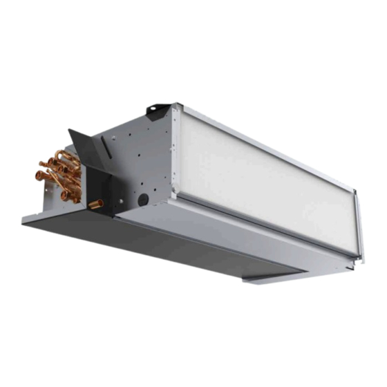
- Page 1 Installation and maintenance manual SYSCOIL COMFORT 10 / 80 Fan coil units 0.61 â 12.90kW 0.51 â 9.07kW 68 â 1 548m...
- Page 3 INSTALLATION INSTRUCTION English NOTICE D’INSTALLATION Français INSTALLATIONSHANDBUCH Deutsch ISTRUZIONI INSTALLAZIONE Italiano INSTRUCCIONES DE INSTALACIÓN Español...
-
Page 4: Table Of Contents
2 SYSCOIL COMFORT CONTENTS 1. GENERAL RECOMMENDATIONS ................................ 3 1.1. SAFETY DIRECTIONS ............................................3 1.2. WARNING ................................................. 3 2. INSPECTION AND STORAGE ................................4 3. WARRANTY ...................................... 4 4. TECHNICAL SPECIFICATIONS ................................4 4.1. OPERATING LIMITS ............................................4 4.2. ELECTRICAL SPECIFICATIONS ......................................... 4 4.2.1. -
Page 5: General Recommendations
SYSCOIL COMFORT POWER SUPPLY MUST BE SWITCHED OFF BEFORE STARTING WORK IN THE ELECTRIC CONTROL BOX 1. GENERAL RECOMMENDATIONS The purpose of this Manual is to provide users with instructions for installing, commissioning, using and maintaining the units. It also contains instructions on starting up the machine as well as recommendations to avoid bodily injury and risks of damage to the device during its operation. -
Page 6: Inspection And Storage
4 SYSCOIL COMFORT 2. INSPECTION AND STORAGE At the time of receiving the equipment carefully cross check all the elements against the shipping documents in order to ensure that all the crates and boxes have been received. Inspect all the units for any visible or hidden damage. -
Page 7: With Electric Heating
SYSCOIL COMFORT 4.2.2. WITH ELECTRIC HEATING Electric heating capacity Fuse rating Gg Fuse rating ASE / VDE Cable section mini Size mm² SCC10 3G1.5 SCC20 3G1.5 3G1.5 SCC30 1 000 3G1.5 1 250 3G2.5 SCC40 1 250 3G2.5 SCC50 2 500 3G2.5 1 250 3G2.5... -
Page 8: Clearance
6 SYSCOIL COMFORT 7.1. CLEARANCE 7.2. UNIT LOCATION Caution The unit base shall be arranged as indicated in the manual. There could be a risk of personal injury or damage to property in the event of the unit being incorrectly supported. The unit must be installed on a firm level foundation, of adequate strength to support its full operating weight. -
Page 9: Hn / Hc Ceiling Unit
SYSCOIL COMFORT 7.3.2. HN / HC CEILING UNIT The HN / HC units are designed for ceiling mounting. Recommended fixing by M8 threaded rod or 8 mm diameter anchor bolts (contractor supply). When the HN units are ducted at the inlet side, the controller return sensor must be located outside the fan compartment in order to ensure its good operation. -
Page 10: Hydraulic Connections
8 SYSCOIL COMFORT Withdraw the four screws that hold the casing attached to the two chassis flanks. Then, lift the casing vertically by pulling its forwards. Place it carefully to one side. 8. HYDRAULIC CONNECTIONS Caution The fan-coil units may contain a small amount of oil incompatible with plastic polyethylene piping (PER/HTA/PVC). -
Page 11: Coil Water Connections
SYSCOIL COMFORT 8.3. COIL WATER CONNECTIONS Air vents orifices The units are equipped, in their standard 2-pipes configuration, with a main chilled water coil with 2 rows (SCC10), 3 rows (SCC20 to SCC80). In the 4-pipes configuration, the unit is equipped , in the same block with 3 rows (SCC10), 4 rows (SCC20 to SCC80), with chilled water coil and heated water coil 1 row (on an independent circuit). -
Page 12: Water Connection Of Control Valves
10 SYSCOIL COMFORT 8.3.2. WATER CONNECTION OF CONTROL VALVES The use of regulation valves (supplied as an accessory or by the client) is mandatory to ensure that the appliance operates correctly. 2-way on/off 3-way on/off valves valves Caution The installation and operating conditions require the MANDATORY fitting of a valve ON the unit OR/AND upstream in the hydraulic circuit. -
Page 13: Water Quality
SYSCOIL COMFORT 8.6. WATER QUALITY The water must be analyzed; the hydraulic network system installed must include all elements necessary for water treatment: filters, additives, intermediate exchangers, drain valves, vents, check valves, etc., according to the results of the analysis. Caution The SYSCOIL COMFORT must not run on a network with open loops, likely to cause incidents related to oxygenation, or with non treated table water. -
Page 14: Electrical Connections
12 SYSCOIL COMFORT 9. ELECTRICAL CONNECTIONS WARNING Before carrying out any work on the equipment, make sure that the electrical power supply is disconnected and that there is no possibility unit being started inadvertently. Non-compliance with the above instructions can lead to injury or death by electrocution. 9.1. -
Page 15: Optional Electric Heater
SYSCOIL COMFORT Before making the connections, be sure that the available power supply has the same voltage and phase as that shown on the fan coil unit nameplate. Each fan coil unit is supplied with a terminal strip located on the opposite side of piping connections. Line and low voltage wiring must be done in accordance with electrical code whichever is applicable. -
Page 16: Controls Connections
14 SYSCOIL COMFORT 9.5.1. CONTROLS CONNECTIONS The connection is different depending on the selected control accessory: SysLogic TControl EASY TRM-FA ² ² ² TControl POD TAE20 ² ² SEE APPENDIX 9.5.1.1. SYSLOGIC SEE SPECIFIC MANUAL 9.5.1.2. TCONTROL EASY SEE SPECIFIC MANUAL 9.5.1.3. - Page 17 SYSCOIL COMFORT 9.5.1.4.4. ELECTRICAL CONNECTIONS Connection of the thermostat TRM-FA. Connections should be made according to the diagram (SEE APPENDIX). Max. cross-sectional area of wires : 2,5 mm2 9.5.1.4.5. WALL MOUTING Remove the thermostat control knob, the screw and the cover. ²...
- Page 18 16 SYSCOIL COMFORT 9.5.1.5. TAE20 ROOM THERMOSTAT 9.5.1.5.1. FIELDS OF APPLICATION Regulating ambient temperature in rooms heated or cooled. ² Opening and closing the valve. ² Cutting in and out the electric heating. ² Controlling the three fan speed. ² 9.5.1.5.2.
-
Page 19: Commissioning
SYSCOIL COMFORT 10. COMMISSIONING 10.1. PRE-START CHECK LIST 10.1.1. ELECTRICAL CHECK 1. Electrical installation has been carried out according to unit wiring diagram and the Supply Authority Regulations. 2. Size fuses or circuit breaker has been installed at the main switchboard. 3. -
Page 20: In Case Of Warranty - Material Return Procedure
18 SYSCOIL COMFORT 12. IN CASE OF WARRANTY - MATERIAL RETURN PROCEDURE Material must not be returned without permission of our After Sales Department. To return the material, contact your nearest sales office and ask for a "return form". The return form shall be sent with the returned material and shall contain all necessary information concerning the problem encountered. -
Page 21: Air Filter
SYSCOIL COMFORT 14.1.2. AIR FILTER Changing the filter is a maintenance operation that should only be performed by qualified personnel. To avoid clogging of air filter, it is recommended to clean it regularly. Filter changes are required at the regular intervals. The time period between changes will depend upon the specific operating conditions. -
Page 22: Condensate Recovery Tray
20 SYSCOIL COMFORT 14.1.3. CONDENSATE RECOVERY TRAY 1. Check that the drainage orifices, conduits and siphon are not blocked. 2. Eliminate all accumulated dirt. 3. Check that no traces of rust are present. 4. If required, it can be cleaned and washed with water. 14.1.4. - Page 23 APPENDIX / ANNEXE / ANLAGE / ALLEGATO / ANEXO APPENDIX ANNEXE ANLAGE ALLEGATO ANEXO...
- Page 24 APPENDIX / ANNEXE / ANLAGE / ALLEGATO / ANEXO APPENDIX DIMENSIONS ................III WIRING DIAGRAM ..............VIII SYSCOIL COMFORT VC / HC ................III SE 4546 - SYSCOIL COMFORT AC MOTOR TERMINAL BLOCK ....IX SYSCOIL COMFORT VN / HN WITHOUT DRAIN GUARD ......IV SE 4729 - SYSCOIL COMFORT AC MOTOR SYSLOGIC ........X SYSCOIL COMFORT VN WITH DRAIN GUARD ..........
- Page 25 APPENDIX / ANNEXE / ANLAGE / ALLEGATO / ANEXO DIMENSIONS DIMENSIONS ABMESSUNGEN DIMENSIONI DIMENSIONES SYSCOIL COMFORT VC / HC Discharge Return Ground level Weight SCC10 415.5 61 SCC20 415.5 61 SCC30 415.5 61 SCC40 415.5 61 1 136 477 SCC50 415.5 61 1 321 477 SCC60...
- Page 26 APPENDIX / ANNEXE / ANLAGE / ALLEGATO / ANEXO SYSCOIL COMFORT VN / HN WITHOUT DRAIN GUARD Discharge Return Weight SCC10 66.5 185.5 189 415.5 61 569.5 430 SCC20 66.5 185.5 189 415.5 61 569.5 430 SCC30 415.5 61 SCC40 415.5 61 SCC50 415.5 61...
- Page 27 APPENDIX / ANNEXE / ANLAGE / ALLEGATO / ANEXO SYSCOIL COMFORT VN WITH DRAIN GUARD Discharge Return Ground level Weight SCC10 66.5 185.5 189 415.5 61 692.5 430 SCC20 66.5 185.5 189 415.5 61 692.5 430 SCC30 415.5 61 SCC40 415.5 61 1 061 430 SCC50...
- Page 28 APPENDIX / ANNEXE / ANLAGE / ALLEGATO / ANEXO SYSCOIL COMFORT HN WITH DRAIN GUARD Discharge Return Wall Weight SCC10 66.5 185.5 189 415.5 61 692.5 430 SCC20 66.5 185.5 189 415.5 61 692.5 430 SCC30 415.5 61 SCC40 415.5 61 1 061 430 SCC50 415.5 61...
- Page 29 APPENDIX / ANNEXE / ANLAGE / ALLEGATO / ANEXO HYDRAULIC CONNECTIONS - SYSCOIL COMFORT VN / VC Right - 2 pipes Left - 2 pipes Discharge Return Return Discharge Inlet Outlet Inlet Outlet 2 pipes 4 pipes Ground level Ground level Right - 4 pipes Left - 4 pipes Discharge...
- Page 30 APPENDIX / ANNEXE / ANLAGE / ALLEGATO / ANEXO WIRING DIAGRAM SCHEMAS ELECTRIQUES STROMLAUFPLANS SCHEMA ELETRICO ESQUEMA ELECTRICO TAKE CARE! These wiring diagrams are correct at the time of publication. Manufacturing changes can lead to modifications. Always refer to the diagram supplied with the product. ATTENTION Ces schémas sont corrects au moment de la publication.
- Page 31 APPENDIX / ANNEXE / ANLAGE / ALLEGATO / ANEXO SE 4546 - SYSCOIL COMFORT AC MOTOR TERMINAL BLOCK SYSCOIL COMFORT...
- Page 32 APPENDIX / ANNEXE / ANLAGE / ALLEGATO / ANEXO SE 4729 - SYSCOIL COMFORT AC MOTOR SYSLOGIC X SYSCOIL COMFORT...
- Page 33 APPENDIX / ANNEXE / ANLAGE / ALLEGATO / ANEXO SE 4550 - SYSCOIL COMFORT EC MOTOR TERMINAL BLOCK SYSCOIL COMFORT...
- Page 34 APPENDIX / ANNEXE / ANLAGE / ALLEGATO / ANEXO SE 4730 - SYSCOIL COMFORT EC MOTOR SYSLOGIC XII SYSCOIL COMFORT...
- Page 35 APPENDIX / ANNEXE / ANLAGE / ALLEGATO / ANEXO SE 4554 - SYSCOIL COMFORT EC MOTOR TERMINAL BLOCK WITHOUT ECOSPEED3 SYSCOIL COMFORT XIII...
- Page 36 APPENDIX / ANNEXE / ANLAGE / ALLEGATO / ANEXO 2-PIPE COILS 4-PIPE COILS COOLING HEATING LOW SPEED MEDIUM SPEED HIGH SPEED BATTERIES BATTERIES FROID CHAUD PETITE VITESSE VITESSE MOYENNE GRANDE VITESSE 2 TUBES 4 TUBES 2 LEITER 4 LEITER KLEINE MITTLERE HOHE KÜHLUNG...
- Page 37 APPENDIX / ANNEXE / ANLAGE / ALLEGATO / ANEXO + SW TRM-FA TRM-FA TRM-FA TRM-FA TRM-FA TRM-FA TRM-FA...
- Page 38 APPENDIX / ANNEXE / ANLAGE / ALLEGATO / ANEXO...
- Page 40 As part of our ongoing product improvement programme, our products are subject to change without prior notice. Non contractual photos. Systemair AC SAS Route de Verneuil 27570 Tillières-sur-Avre FRANCE & : +33 (0)2 32 60 61 00 6 : +33 (0)2 32 32 55 13...
Need help?
Do you have a question about the SYSCOIL COMFORT 10 and is the answer not in the manual?
Questions and answers