Table of Contents
Advertisement
Quick Links
G
Installation manual
SAVEWALL HRV NEXT
Read this manual carefully before using the product and keep it in a safe
place for reference.
This product was constructed up to standard and in compliance with
regulations relating to electrical equipment and must be installed by
technically qualified personnel.
The manufacturer assumes no responsibility for damage to persons or
property resulting from failure to observe the regulations contained in this
booklet.
PRECAUTIONS FOR INSTALLATION, USE AND MAINTENANCE
• T he device should not be used for applications other than those specified in this manual.
• A fter removing the product from its packaging, verify its condition. In case of doubt, contact a qualified technician. Do not
leave packaging within the reach of small children or people with disabilities.
• D o not touch the appliance with wet or damp hands/feet.
• T his appliance can be used by children aged from 8 years and above and persons with reduced physical, sensory or
mental capabilities or lack of experience and knowledge if they have been given supervision or instruction concerning use
of the appliance in a safe way and understand the hazards involved. Children shall not play with the appliance. Cleaning
and user maintenance shall not be made by children without supervision.
• D o not use the product in the presence of inflammable vapours, such as alcohol, insecticides, gasoline, etc.
• I f any abnormalities in operation are detected, disconnect the device from the mains supply and contact a qualified
technician immediately. Use original spare parts only for repairs.
• T he electrical system to which the device is connected must comply with regulations.
• B efore connecting the product to the power supply or the power outlet, ensure that:
- the data plate (voltage and frequency) correspond to those of the electrical mains
- the electrical power supply/socket is adequate for maximum device power. If not, contact a qualified technician.
• T he device should not be used as an activator for water heaters, stoves, etc., nor should it discharge into hot air/fume vent
ducts deriving from any type of combustion unit. It must expel air outside via its own special duct.
• O perating temperature: -20°C up to +50°C.
• T he device is designed to extract clean air only, i.e. without grease, soot, chemical or corrosive agents, or flammable or
explosive mixtures.
• D o not leave the device exposed to atmospheric agents (rain, sun, snow, etc.).
• D o not immerse the device or its parts in water or other liquids.
• T urn off the main switch whenever a malfunction is detected or when cleaning.
• F or installation an omnipolar switch should be incorporated in the fixed wiring, in accordance with the wiring regulations, to
provide a full disconnection under overvoltage category III conditions (contact opening distance equal to or greater than 3mm).
• I f the supply cord is damaged, it must be replaced by the manufacturer, its service agent or similarly qualified persons in
order to avoid a hazard.
• D o not obstruct the fan or exhaust grille to ensure optimum air passage.
• E nsure adequate air return/discharge into/from the room in compliance with existing regulations in order to ensure proper
device operation.
• I f the environment in which the product is installed also houses a fuel-operating device (water heater, methane stove etc.,
that is not a "sealed chamber" type), it is essential to ensure adequate air intake, to ensure good combustion and proper
equipment operation.
INTRODUCTION
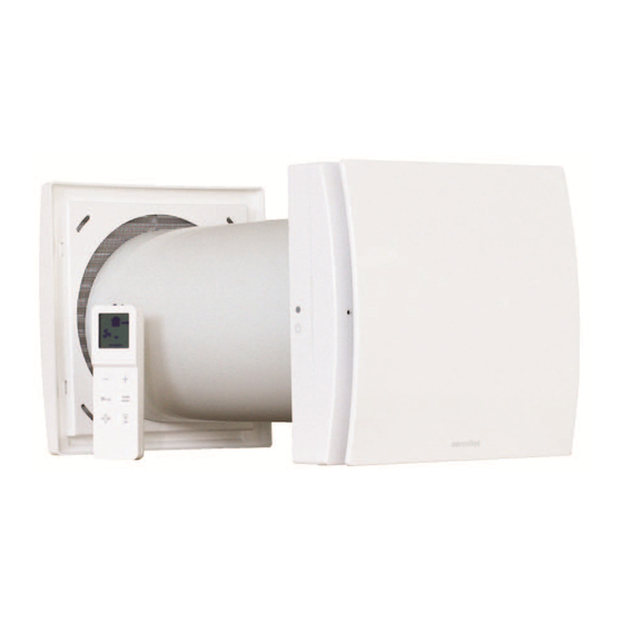
SAVEWALL HRV NEXT is a single alternate flow decentralized (single point) residential heat recovery unit, also called
«push&pull» unit, designed to ensure adequate ventilation in enclosed environments without energy losses.
It is recommended that two units are installed in a pair: when one unit is pulling, the other is pushing.
The pair of units can be installed in the same room or in different rooms (i.e. living-room and bedroom). The unit is suitable
for installation on an outside wall.
The unit should operate continuously, and only stopped for maintenance or service.
When heat exchange is not useful (for example in mid-seasons when indoor and outdoor temperatures are similar), or
when heat exchange is not recommended (for example with the option "summer free cooling"), it is recommended to set
the unit in "extract-only" or "intake-only" mode and NOT to switch it off.
Fig.1
1
Advertisement
Table of Contents

Related Manuals for SystemAir SAVEWALL HRV NEXT


Summary of Contents for SystemAir SAVEWALL HRV NEXT
- Page 1 INTRODUCTION SAVEWALL HRV NEXT is a single alternate flow decentralized (single point) residential heat recovery unit, also called «push&pull» unit, designed to ensure adequate ventilation in enclosed environments without energy losses. It is recommended that two units are installed in a pair: when one unit is pulling, the other is pushing.
-
Page 2: Technical Specifications
TECHNICAL SPECIFICATIONS • D esign front cover (A) removable for cleaning without the use of tools. • I nner ventilation unit (B) and wall support base (D) made of high quality, impact and UV-resistant ABS, colour RAL 9010. • I ntegrated multi-colour led (C ) to obtain a visual feedback of the unit status. • S mart humidity control. • I ntegral temperature sensor for the automatic management of the inversion time (comfort mode) • A utomatic anti-frost protection to prevent frost building up on the heat exchanger. - Page 3 The unit is supplied with an infrared remote controller (K) as standard, as well as its support base (L) which can be wall mounted. A magnet keeps the controller attached to the base. The controller is equipped with an LCD display to visualise the setting to be transferred to the unit; anytime a touch button is pressed, the setting shown on the LCD display is transferred to the unit. The IR receiver (J fig. 2) is placed on the left side of cambio batterie telecomando the ventilation unit: it is recommended to point the controller towards the receiver when any setting needs to be transfered. One remote controller can control more units.
-
Page 4: Maintenance
Filter reset Every 3 months a yellow warning led switches on (fixed light) to indicate FILTER that the filters have to be maintained. Press the dedicated button for 5 green short RESET seconds to reset the timing. Smart humidity control When the humidity sensor detects a quick variation of the Relative Humidity level, the running speed automatically increases to the next higher speed. After 10 minutes from the last quick RH variation, the unit returns running at the selected speed. The smart humidity control is active flashing blue if the airflow direction is set on alternate or extract only: if speed 5 has been selected, no speed increase happens. - Page 5 DIMENSIONS (mm) 26,5 300÷560 218 26,5 26,5 218 ARCHIVIO CAD: \Progetti\..\ colorare filtro e strisce mousse INSTALLATION contenuto imballo modello Quantum NEXT (sostituisce immagine 1 ) contenuto imballo modello Quantum NEXT (sostituisce immagine 1 ) sostituire possibilmente solo il tubo nell'im fig.1 colorare filtro e strisce mousse colora...
- Page 6 insulation foam INIZIO INSTALLAZIONE aggiungere freccia SOTTOTRACCIA x aprire il coperchietto RECESSED CABLE ENTRY INIZIO INSTALLAZIONE aggiungere freccia SOTTOTRACCIA x aprire il coperchietto H03VV-F ; H05VV-F 2 X 0,5 ÷ 1,5 mm aggiungere freccia x togliere passacavo apertura presfond aggiungere freccia x togliere passacavo apertura presfondabile Ø...
- Page 7 4 x Ø5mm...
- Page 8 colorare filtro 115 mm CLICK...
-
Page 9: Collegamenti Elettrici
SURFACE CABLE (for one unit wiring) H03VV-F ; H05VV-F 2 X 0,5 ÷ 1,5 mm INIZIO INSTALLAZIONE INIZIO INSTALLAZIONE SUPERFICIE aggiungere freccia SOTTOTRACCIA x aprire il coperchietto INIZIO INSTALLAZIONE aggiungere freccia SOTTOTRACCIA x aprire il coperchietto Ø 5 mm Ø 5 mm 4 x Ø5mm aggiungere freccia x togliere passacavo... - Page 10 aggiungere freccia aggiungere freccia x avvitare viti fermacavo x chiudere il coperchietto...
- Page 11 115 mm aggiungere ai lati del prodotto simboli di "avvenuto aggancio" CLICK aggiungere scritte REMOTE CONTROLLER WALL MOUNTING ALTO - TOP aggiungere frecce x distacco telecomando dalla base Ø5mm...
- Page 12 EXTERNAL GRILLE 3-5mm Ø 5x40mm MAINTENANCE E E DUE LE INSTALLAZIONI) aggiungere frecce x distacco parte ventilante...
- Page 13 colorare filtro e strisce mousse colorare filtro e strisce mousse aggiungere frecce per inserimento scambiatore...
- Page 14 CLICK MAINTENANCE/CLEANING REGISTER FILTER CLEANING FILTER REPLACEMENT HEAT EXCHANGER CLEANING DATE DATE DATE DATE DATE DATE DATE DATE...
-
Page 15: Standard Conformity
TROUBLE SHOOTING ANOMALY POSSIBLE CAUSE SOLUTION No icon shown on the controller LCD Batteries are dead Change the batteries display Batteries are not present Check that batteries are in there Batteries are wrongly positioned Position the batteries correctly The unit does not execute the Lack of communication between the unit and the Go closer to the unit, pointing the controller to the command sent from the remote control remote controller receiver on the left side of the unit... - Page 16 ErP Directive - Regulations 1253/2014 - 1254/2014 SYSTEMAIR a) Mark SAVEWALL HRV NEXT b) Model c) SEC class c1) SEC warm climates kWh/m2.a -18,1 c2) SEC average climates kWh/m2.a -41,7 c3) SEC cold climates kWh/m2.a Energy label d) Unit typology...
- Page 17 NOTES...
- Page 18 NOTES...
- Page 19 NOTES...
- Page 20 Systemair Hellas SA Astrous 13, Ilion, 13121, Greece Phone: 0030 210 57 89 766, Fax: 0030 210 57 89 768 www.systemair.gr info@systemair.gr 004047 - 00 - 0618...
Need help?
Do you have a question about the SAVEWALL HRV NEXT and is the answer not in the manual?
Questions and answers