Table of Contents
Advertisement
Quick Links
Мультизональные системы SYSVRF
Хладагент R410A
ИНСТРУКЦИЯ ПО МОНТАЖУ
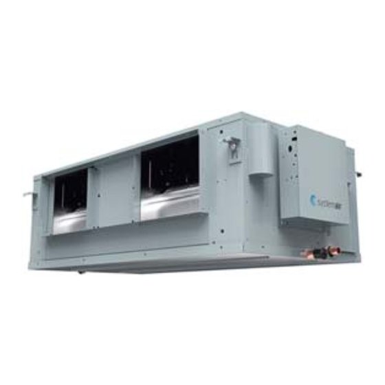
Внутренние блоки
канального типа
высоконапорные
SYSVRF2 DUCT HP 71 Q
SYSVRF2 DUCT HP 112 Q
SYSVRF2 DUCT HP 140 Q
SYSVRF2 DUCT HP 200 Q
SYSVRF2 DUCT HP 280 Q
Тщательно изучите данную инструкцию
и сохраняйте ее для использования в работе с оборудованием
Advertisement
Table of Contents

Related Manuals for SystemAir SYSVRF2 DUCT HP 71 Q


Summary of Contents for SystemAir SYSVRF2 DUCT HP 71 Q
- Page 1 Мультизональные системы SYSVRF Хладагент R410A ИНСТРУКЦИЯ ПО МОНТАЖУ Внутренние блоки канального типа высоконапорные SYSVRF2 DUCT HP 71 Q SYSVRF2 DUCT HP 112 Q SYSVRF2 DUCT HP 140 Q SYSVRF2 DUCT HP 200 Q SYSVRF2 DUCT HP 280 Q Тщательно изучите данную инструкцию...
- Page 2 Производитель оставляет за собой право вносить изменения в конструкцию, дизайн и функциональные возможности оборудования без уведомления. Наиболее актуальную информацию можно получить на сайтах www.systemair-ac.ru, www.systemair.ru.
-
Page 3: Table Of Contents
Contents • Use only electrical cables that fulfil the specifications. All wiring on Installaion Manual................1 site must be carried out in accordance with the connection diagram attached to the product. Make sure that there are no external forces Accessories..................2 acting on the terminals and wires. Improper wiring and installation 1. -
Page 4: Installaion Manual
• When mounting the indoor and outdoor units, make sure the power cord is installed at a distance of at least 1 m away from any TV or radio so as to prevent noise or interference with the images. • The refrigerant required for the installation is R410A. Make sure the refrigerant is correct before installation. Incorrect refrigerant may cause the unit to malfunction. -
Page 5: Before Installation
Expansion hook To purchase based on actual For installation of project requirements. anchor indoor unit. To purchase based on actual For installation of Mounting hook project requirements. indoor unit. To purchase based on actual To purchase based on actual Tie for connecting wire project requirements. - Page 6 Steel framework Caution • All bolts should be made from high quality carbon steel (with Directly set and use an angled steel rod for support. galvanized surface or other rust prevention treatment) or stainless steel. • How the ceiling should be handled will differ with the type of building.
- Page 7 3.3 Dimensions 3.3.1 Installation dimensions of lifting bolts and location size of connecting piping (unit: mm) Unit: mm 7.1~11.2KW Figure 3.7...
- Page 8 Unit: mm 14.0~16.0KW Figure 3.8...
- Page 9 Unit: mm 20.0~28.0KW 342(W) 68.5 Figure 3.9...
- Page 10 Unit: mm 56.0KW Repair hole Figure 3.10...
-
Page 11: Refrigerant Piping Installation
4. Refrigerant Piping Installation Before the socket cap is installed on the pipe socket, apply some refrigerant oil on the socket (both inside and outside), and then rotate 4.1 Length and Level Difference Requirements for the Piping it three or four times before you tighten the cap. See Figure 4.3. Connections to the Indoor and Outdoor Units Apply refrigerant oil The length and level difference requirements for the refrigerant piping... -
Page 12: Water Discharge Piping Installation
5. Water Discharge Piping Installation 9. Install the water storage elbow. 5.1 Water Discharge Piping Installation for Indoor Unit (1) For a water discharge duct connected to the main drain pan in the indoor unit, the water discharge piping must include a water 1. -
Page 13: Air Duct Installation
6. Air Duct Installation 6.1 Piping Design and Installation (1) In order to prevent short-circuit air delivery, the piping for air outlet and air return ducts must not be too close. (2) The indoor unit does not have an air filter installed. The air filter must be installed at a location like an air inlet where it can be easily maintained. (Without an air filter, dust particles may stick to the air heat exchanger which will make the air conditioner prone to failures and water leakage.) (3) Before installing the air duct, ensure that the static pressure of the air duct is within the permitted range of the indoor unit (see section 6.2). - Page 14 9.0KW 200Pa 190Pa 180Pa 170Pa 160Pa 150Pa 140Pa 130Pa 120Pa 110Pa 100Pa(default) 90Pa 80Pa 70Pa 60Pa 50Pa 30Pa 1130 1180 1230 1280 1330 1380 1430 Air flow (m 11.2KW 200Pa 190Pa 180Pa 170Pa 160Pa 150Pa 140Pa 130Pa 120Pa 110Pa 100Pa(default) 90Pa 80Pa 70Pa...
- Page 15 16.0KW 200Pa 190Pa 180Pa 170Pa 160Pa 150Pa 140Pa 130Pa 120Pa 110Pa 100Pa(default) 90Pa 80Pa 70Pa 60Pa 50Pa 30Pa 1870 1920 1970 2020 2070 2120 2170 2220 2270 2320 2370 2420 2470 2520 2570 2620 2670 Air flow (m 20.0/25.0/28.0KW 250Pa 230Pa 210Pa 200Pa...
-
Page 16: Electrical Connection
Set proper external static pressure (ESP) according to the actual installation Figure 7.2 shows the power supply terminal of the indoor unit. conditions. Otherwise it may cause some problems. If the connecting duct is long and the ESP setting is small, the airflow will be very small, leading to poor performance. -
Page 17: Master Wired Controller Slave Wired Controller
7.3.2 Communication wiring between the indoor unit and wired controller Table 7.2 Indoor units electrical characteristics The wired controller and the indoor unit can be connected in different manners, Power supply depending on the forms of communication. Model name 1) For a bidirectional communication mode: Volts Use 1 wired controller to control 1 indoor unit or 2 wired controllers 7.1kW... -
Page 18: On-Site Configuration
8.2 Address Settings The X1, X2, D1, D2 ports on the sides of the main control board and the unidirectional communication port (display board side) are for different When this indoor unit is connected to the outdoor unit, the outdoor unit types of wired controllers (see Figure 7.10). -
Page 19: Test Run
8.4 Error Codes and Definitions In heating mode when the set temperature has been reached, the fan operates in a 4 minutes off / 1 minute on Error repeating cycle Content code In heating mode when the set temperature has been reached, the fan operates in an 8 minutes off / 1 minute on repeating cycle Mode conflict... - Page 20 Operation Manual • Do not remove the remote controller’s front or back overs and do not touch the remote controller’s internal components, as doing so can There are two types of precautions as described below: cause injury. If the remote controller stops working, contact your Warning: Failure to comply may lead to death or serious injury.
-
Page 21: Part Names
• This appliance can be used by children aged from 8 years and above and persons with reduced physical, sensory or mental ■ High static pressure duct type capabilities or lack of experience and knowledge if they have been given supervision or instruction concerning use of the appliance in Air Intake a safe way and understand the hazards involved. -
Page 22: Air Conditioner Operations And Performance
13. Adjusting Air Flow Direction 12. Air Conditioner Operations and Performance Since warmer air rises and cooler air falls, the distribution of The operating temperature range under which the unit runs stably are given in warmed/cooled air around a room can be improved by positioning the below table. -
Page 23: Symptoms That Are Not Faults
15. Symptoms That Are Not Faults The following symptoms may be experienced during the normal operation of the unit and are not considered faults. Note: If you are not Loosen the bolts and sure whether a fault has occurred, contact your supplier or service dismantle the filter. - Page 24 16.2 Unit Troubleshooting Symptom Possible causes Troubleshooting steps A power cut has occurred (the power to the Wait for the power to come back on. premises has been cut-off). Power on the unit. This indoor unit forms part of an air conditioning system that has multiple indoor units that are all connected.
- Page 25 16.3 Remote Controller Troubleshooting Warning: Certain troubleshooting steps that a professional technician may perform when investigating an error are described in this owner's manual for reference only. Do not attempt to undertake these steps yourself – arrange for a professional technician to investigate the problem. If any of the following errors occur, power the unit off and contact a professional technician immediately.
- Page 26 16.4 Error Codes With the exception of a mode conflict error, contact your supplier or service engineer if any of the error codes listed in the following table are displayed on the unit's display panel. If the mode conflict error is displayed and persists, contact your supplier or service engineer. These errors should only be investigated by a professional technician.
- Page 27 16126000003207 V2.0...
- Page 28 Оборудование сертифицировано:...
Need help?
Do you have a question about the SYSVRF2 DUCT HP 71 Q and is the answer not in the manual?
Questions and answers