
Related Manuals for QSC RAVE 520uz


Summary of Contents for QSC RAVE 520uz
- Page 1 RAVE 520uz 8 input CobraNet Enabled Signal Processor Hardware Manual *TD-000201-00* TD-000201-00 rev.A...
- Page 2 - Consult the dealer or an experienced radio or TV technician for help. © Copyright 2005 QSC Audio Products, Inc. QSC® is a registered trademark of QSC Audio Products, Inc. “QSC” and the QSC logo are registered with the U.S. Patent and Trademark Office. All trademarks are the property of their respective owners.
- Page 3 RAVE devices in a system are configured, a computer is no longer required on that system’s network. All basic func- tions of the RAVE 520uz continue to operate with or without a control computer connected to the network. The configurable DSP engine provides all of the functions necessary to handle the input portion of a signal chain, such as delays, equalization, compression/limiting, etc.
- Page 4 Introduction (continued) Unlike other configurable DSP boxes, the intrinsic process- ing latency of the RAVE 520uz is both short and fixed at 0.396 milliseconds. The delay does not change regardless of the DSP configuration, unless the configuration intention- ally adds more delay.
- Page 5 The RAVE 520uz supports two distinct kinds of network activity; the first is audio transport via CobraNet, and the second is DSP setup via QSControl.net. The user can choose to install one network for CobraNet traffic and a second separate network for QSControl.net traffic.
- Page 6 100 Mbps. Obviously, we recommend taking advantage of switch network technology whenever possible. It should be noted here that while the CobraNet port on a RAVE 520uz is restricted to repeater LAN or switch LAN deployments, QSCon- trol.net is a TCP/IP standards-compliant network system and therefore supports operation on network repeaters, switches and routers.
- Page 7 RAVE 522aa.The RAVE 520uz is the audio “source” in this example. Use a CAT-5 crossover cable connected between the Cobra- Net ports of each unit. No network switch is required. This connection allows audio to pass from the RAVE 520uz to the BASIS/RAVE unit over CobraNet.
- Page 8 This configuration works well when CobraNet audio deliveries are point to point. Though the example shows only one RAVE 520uz and one “audio destination” product (such as the BASIS 922az) as many devices may be connected as there are available switch ports.
- Page 9 All RAVE units will be able to communicate with the computer. All destination products will have CobraNet audio, providing a CobraNet source (i.e. RAVE 520uz) is putiing audio data onto the network. Switches can be connected...
- Page 10 Example #5 - Two-Wire Interface (separate network hardware): Example #5 is conceptually similar to example #4. The difference here is that separate networks are created by providing each local area network (LAN) with its own network switch. Therefore, traffic segmentation is physical rather than logical. Example #5 also pro- vides an additional level of fault tolerance, although at the expense of additional network hardware.
-
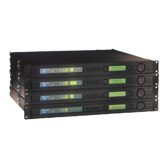
Page 11: Rack Mounting
2-pin terminal block connector Mounting The RAVE 520uz can be used in or out of an equipment rack. Rack mounting is optional. Adhesive rubber feet are included for non-rack mount installations. Use them to prevent the unit from scratching or marring support surfaces. - Page 12 Computer Requirements & Software Installation Installing QSControl.net is easy. All you need to do is choose the folder where the program is to be stored (the default setting is accept- able for most applications). We recommend your system meet the following minimum requirements: 1- IBM PC compatible computer with a Pentium 4 processor.
-
Page 13: Configuration Memories
Configuration Memories The RAVE 520uz has non-volatile storage locations that contain settings for the device as well as DSP signal flow. The storage loca- tions make it possible to set up the RAVE for different situations and quickly recall the setup with or without QSControl.net software... - Page 14 Insert the molded receptacle of the AC power cord into the AC power inlet on the back of the RAVE 520uz. Plug the AC line connec- tor into the AC outlet. The power supply will accept from 100 to 240 Volts AC, 47 to 440 Hertz, without any changes.
-
Page 15: Relay Out
8 data bits, 1 stop bit, and flow control Xon/Xoff. LED Indicators When the RAVE 520uz is plugged into a properly functioning AC out- let, it will power up and briefly display a welcome screen on the LCD display. -
Page 16: Lcd Display And Controls
LCD Display and Controls The RAVE 520uz has a 2 line X 16 character LCD display. The display and the multi-function push-button switches on either side provide data access and editing capability. The push-button switches on either side of the display are used to navigate through the menus. - Page 17 LCD Navigation Map Left side buttons have screen dependent functions. This read-only screen is the “out of the box” default display after power up. This is the most desired information when first setting up a network system. Once user moves to a different screen, the last screen accessed becomes the new power up default.
-
Page 18: Getting Started
2- Connect a CAT-5 crossover cable from the computer’s network interface card (NIC) to the RAVE QSControl jack (example 1, page 6). 3- Reconnect the power cord to the RAVE 520uz (turn it on). Using the RAVE LCD display and controls, navigate the menu to the IP Address and make a note of it. - Page 19 RAVE. 19- Click on the “+” sign of the RAVE 520uz in the inventory root, then the “+” sign of the Flashed Configs. Click on the config with the loudspeaker icon. A view of applicable device tabs will open. Click the DSP tab and the current DSP configuration of the RAVE will be displayed.
-
Page 20: Operation
16 may be selected to forward to the signal processing chain (DSP engine). The RAVE 520uz will support the delivery of up to 32 channels via up to 4 outbound bundles (to the network). Of these 32 channels, up to 24 may be unique (processed individually... -
Page 21: Safemode Switch
If the RAVE 520uz operates in an unexpected way or is not responding to any communications after a new firmware file is uploaded to it, it is likely the file was corrupted during transfer. If this occurs, there is a “backup” program in the RAVE 520uz that will enable you to communicate with it. - Page 22 6) The Hyper Terminal main window will appear next, but blank. Type the letter “h” (for help) and then the “Enter” key. This will prompt the RAVE 520uz to post its menu text. The “h” key is the Help prompt for the RAVE 520uz. A text menu will appear. This is sent by the RAVE 520uz and will detail your options and instructions for changing the address information.
-
Page 23: Telnet Access
Basic procedure for opening a Telnet session: 1- To open the Telnet session- Click START, select RUN, type “Telnet” followed by a space, then the IP address of the RAVE 520uz you want to communicate with in the text box and click OK. - Page 24 Preliminary Specification Dynamic Range (AES-17, -60dB Method, all sensitivities) unweighted A weighted Distortion (20Hz-20 KHz, all sensitivities) Gain= 0 - 30dB Gain >30dB Crosstalk (20Hz - 20KHz) inter-channel (max) inter-channel (typ) intra-channel (max) intra-channel (typ) Frequency Response 20Hz - 20KHz (max) 20Hz - 20KHz (typ) Program Inputs Connector Type...
- Page 25 Preliminary Specification Relay Outputs Connector Type Configuration Pinout Switching Capacity (nom) Logic Outputs Connector Type Configuration Pinout Omni Inputs Connector Type Configuration Pinout Normal Operating Range Potentiometer Operation Voltage Tolerance Current Output RS-232 Port QSControl.net CobraNet Indicators QSControl Status CobraNet Status Power Diagnostic LCD Data Display...
- Page 26 Dimensions...
-
Page 28: How To Contact Qsc Audio Products
QSC Audio Products 3 Year Limited Warranty QSC Audio Products, Inc. ("QSC") guarantees its products to be free from defective material and / or workmanship for a period of three (3) years from date of sale, and will replace defective parts and repair malfunctioning products under this warranty when the defect occurs under normal installation and use - provided the unit is returned to our factory or one of our authorized service stations via pre- paid transportation with a copy of proof of purchase (i.e., sales receipt).
Need help?
Do you have a question about the RAVE 520uz and is the answer not in the manual?
Questions and answers