Advertisement
Advertisement
Table of Contents

Related Manuals for QSC Q-SYS Core 1000


Summary of Contents for QSC Q-SYS Core 1000
- Page 1 ™ Type 2 Hardware User Manual Core 1000 – Centralized audio and control processor Core 3000 – Centralized audio and control processor Core 4000 – Centralized audio and control processor I/O Frame – Networked audio and control input and output device Type 2 Hardware TD-000284-00-A *TD-000284-00*...
-
Page 2: Important Safety Instructions
EXPLANATION OF TERMS AND SYMBOLS The term “WARNING!” indicates instructions regarding personal safety. If the instructions are not followed the result may be bodily injury or death. The term “CAUTION!” indicates instructions regarding possible damage to physical equipment. If these instructions are not followed, it may result in damage to the equipment that may not be covered under the warranty. -
Page 3: Fcc Statement
Damage to, or loss of any software or data residing on the product is not covered. When providing repair or replacement service, QSC will use reasonable efforts to reinstall the product’s original software configuration and subsequent update releases, but will not provide any recovery or... -
Page 4: Rohs Statement
If service is required and the original packing material is not available, ensure that the unit is adequately protected for shipment (use a strong box of appropriate size, sufficient packing/padding material to prevent load shifting or impact damage) or call QSC’s Technical Services Group for replacement packing material and a carton. -
Page 5: Ac Power Cord
— Figure 2 — DataPorts The Q-Sys DataPort I/O Card is intended to interface to QSC amplifiers with v1 DataPorts. This is the all-capable version 1 DataPort specification, supported on CX, DCA, PowerLight™, PL2, and PL3 Series amplifiers. All DataPorts use the HD15 connector format and connect to QSC amplifiers via data communications cables having male HD15 connectors. - Page 6 Minimum System Requirements for Q-Sys™ Designer Q-Sys Designer is the software you use to create the designs for a Q-Sys system. After your system is designed, tested and deployed on the Core, Q-Sys designer is not required for that system to operate. Q-Sys Designer runs in a PC environment with the following minimum requirements. Software •...
- Page 7 Quick Start Nuide This is intended to give a high-level procedure for getting a simple Q-Sys system connected, running a Q-Sys design, and passing audio. The following procedure assumes that you have a Q-Sys Designer file with components properly connected, but not necessarily configured. “Qualified 1.
- Page 8 The I/O Frame houses one or more of the following: ◦ DataPort Card (Optional) – provides audio, telemetry, and control interface between Q-Sys and QSC DataPort amplifiers and QSC loudspeakers.
-
Page 9: Network Redundancy
QSC DataPort Amplifiers QSC DataPort amplifiers (PowerLight™, CX, PL2, DCA, and PL3) can be used in a Q-Sys system to communicate with the Q-Sys DataPort card and provides critical telemetry information and protection for both the amplifier and any QSC loudspeaker. Generic amplifiers can be used in a Q-Sys system by connecting the amplifier to a Line Out connection;... -
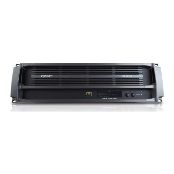
Page 10: Front Panel
Q-Sys Core front and rear panel features for a product having a simple configuration of one blank I/O Card slot. NOTE!: The Q-Sys hardware products are configured at the QSC factory per your order. At the time of order, you specify the type of Q-Sys Audio I/O Card to be installed in the Audio I/O bay on the Q-Sys Core. - Page 11 Cards and two DataPort I/O Cards. NOTE!: The Q-Sys hardware products are configured at the QSC factory per your order. At the time of order, the you specifies the type of Q-Sys Audio I/O Card to be installed in each of the four rear panel audio I/O bays on the Q-Sys I/O Frame. In addition, Q-Sys Audio I/O Card Kits are available for field installation by qualified service personnel.
- Page 12 Q-Sys™ I/O Card Remove and Replace Procedure This procedure is for Q-Sys Type 2 I/O Cards only. Card installation should only be done by a trained and qualified technician. Tools Refer to Figure 9 • Phillips screwdriver • ESD grounded wrist strap •...
- Page 13 Help File in Q-Sys Designer. For more details about the following switches, refer to the manufacturers’ website. The following switches have been tested and qualify for use with a Q-Sys™ network. NOTE!: Refer to the Q-Sys Online help on the QSC website for the latest list of switches. (http://www.qscaudio.com/products/software/QSys/WebHelp/) Linksys HP®...
-
Page 14: Specifications
NPIO Specifications Relay Pins Normal Current Pins High Current Pins Maximum Voltage, relative to Ground: 30 V Maximum Input Range: 0 V to 32 V Maximum Input Range: 0 V to 32 V Maximum Current through Relay: 1 Amp Analog Input Range: 0 V to 24 V Analog Input Range: 0 V to 24 V Digital Input, Low: 0.8 V maximum Power Pins... - Page 15 AES-3 digital audio 48V phantom power 48V phantom power DataPort equipped QSC and high performance amplifiers pre-amplifiers and A/D converters Performance Dynamic Range Unweighted > 105 dB >...
- Page 16 High-Performance AES-3 Mic/Line Input Mic/Line Input Line Output DataPort Output Input/Output CIML4 CIML4-HP COL4 CODP4 CAES4 User-configurable Options (software enabled) Phantom Power +48 V phantom power +48 V phantom power — — — (meets IEC 1938 (meets IEC 1938 [1996] spec) [1996] spec) Output Trim Vrms (max)
- Page 17 QSC support engineer. © 2011 QSC Audio Products, LLC. The QSC logo, QSC and Q-Sys are registered trademarks of QSC Audio Products, LLC and are registered with the US Patent and Trademark office. US and Worldwide Patents Pending. Q-Sys and Intrinsic Correction are trademarks of QSC Audio Products, LLC. AMD is a trademark of Advanced Micro Devices, Inc. Cisco is a trademark of Cisco Systems, Inc.
Need help?
Do you have a question about the Q-SYS Core 1000 and is the answer not in the manual?
Questions and answers