
Subscribe to Our Youtube Channel
Related Manuals for Meyer HOTSHOT-120


Summary of Contents for Meyer HOTSHOT-120
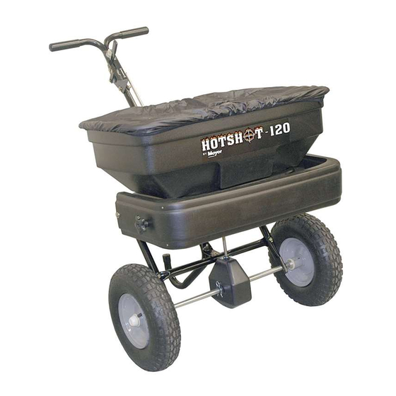
- Page 1 OWNERS MANUAL Model No. 38210 120 LB. PUSH BROADCAST SPREADER CAUTION: Read Rules for Assembly Safe Operation Operation and Instructions Maintenance Carefully Repair Parts...
-
Page 2: Rules For Safe Operation
RULES FOR SAFE OPERATION The following safety precautions are suggested. This 3. Wear eye and hand protection when handling and broadcast spreader is designed, engineered and tested when applying lawn or garden chemicals. to offer reasonably safe and effective service, provided it is operated in strict accordance with these instructions. - Page 3 SHOWN FULL SIZE NOT SHOWN FULL SIZE QTY. DESCRIPTION QTY. DESCRIPTION Hex Bolt, 1/4-20 x 1-3/4" Long Flow Control Link Hex Bolt, 1/4-20 x 1-1/2" Long Spacer Tube Hex Bolt, 1/4-20 x 1" Long Hub Cap Carriage Bolt, 1/4-20 x 3/4" Long Grip Nyock Nut, 1/4-20 Thd.
-
Page 4: Tools Required For Assembly
ASSEMBLY INSTRUCTIONS 5. Place a wheel onto the end of the axle that has a cross hole. The long end of the hub goes to the inside. 6. Assemble a 5/32" x 2" cotter pin through the hole in TOOLS REQUIRED FOR ASSEMBLY the wheel hub and the axle. - Page 5 12. Assemble the leg stand tube to the bottom set of 15. Assemble the flow control arm to the flow control holes in the handle tube (long) using two 1/4" x 1-1/2" mounting bracket using a 1/4" x 1" hex bolt, two nylon hex bolts and 1/4"...
- Page 6 18. Hook the free end of the flow control rod through the 21. Place the adjustable stop into the "ON" end of the slot hole in the slide gate bracket located near the bottom in the top of the flow control mounting bracket. Secure of the hopper.
- Page 7 24. Assemble the spreader shield to the front swivel 28. Position the flow control mounting bracket (figure 15). brackets using two 1/4" x 3/4" carriage bolts, 1/4" a. Push on flow control arm until it locks in "OFF" washers and the two 1/4" plastic knobs. See figure position.
-
Page 8: Operation
OPERATION APPLICATION DIAGRAM HOW TO USE YOUR SPREADER SETTING THE FLOW CONTROL 8' to (Refer to figure 15 on page 7.) 1. Loosen the nylon wing nut, set the adjustable stop to the desired flow rate setting and retighten the wing nut. The higher the setting number, the wider the opening in the bottom of the hopper. -
Page 9: Maintenance
MAINTENANCE SERVICE AND ADJUSTMENTS REPLACING SLOTTED GEAR CHECK FOR LOOSE FASTENERS 1. Before each use make a thorough visual check of 1. If the axle, slotted gear and sprocket assembly is disassembled, mark down the positions of the parts the spreader for any bolts and nuts which may have as they are removed. - Page 10 REPAIR PARTS FOR BROADCAST SPREADER MODEL 38210 47 47...
- Page 11 REPAIR PARTS LIST FOR BROADCAST SPREADER MODEL 38210 REF. PART QTY. DESCRIPTION REF. PART QTY. DESCRIPTION AF41920 AF46055 Spreader Hopper Spring Pin, 1/8 x 1" AFC-9M5732 Pop Rivet, 3/16" AF44285 Delrin Bushing, 3/8" AF48842 AF48934 Frame Tube Agitator Hairpin AF24125 Shield Bracket AF24855 Flow Control Mount Bracket...
-
Page 12: Warranty
Meyer Products LLC warrants to Purchaser the following: Meyer Products LLC, warrants to the original purchaser for a period of one year from the date of purchase of Meyer® brand spreader products that they will be free from defects in materials or workmanship, with the exceptions stated below. No person is authorized to change this warranty or to create any additional warranty on Meyer®...
Need help?
Do you have a question about the HOTSHOT-120 and is the answer not in the manual?
Questions and answers