Table of Contents
Advertisement
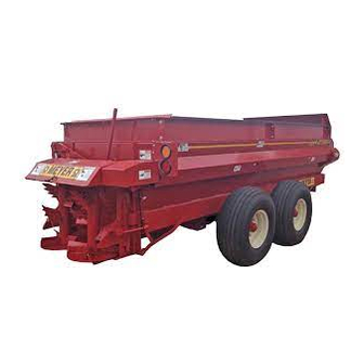
OPERATORS AND PARTS MANUAL NO. 02-7-V-MAX
TWIN EXPELLER SUPER SPREADER
DO NOT OPERATE EQUIPMENT UNTIL THIS MANUAL HAS BEEN READ AND UNDERSTOOD.
11/03
V- MAX
MODELS:
US PATENT NO.
5,368,236
5,501,404
Manufactured by
County Hwy. A West
P.O. Box 405
Dorchester, Wisconsin 54425
Phone 715-654-5132 • FAX 715-654-5513
1-800-325-9103
www.meyermfg.com
E-mail: sales@meyermfg.com
2636
3245
3954
Advertisement
Table of Contents

Subscribe to Our Youtube Channel
Related Manuals for Meyer V-MAX 2636


Summary of Contents for Meyer V-MAX 2636
- Page 1 OPERATORS AND PARTS MANUAL NO. 02-7-V-MAX V- MAX TWIN EXPELLER SUPER SPREADER MODELS: 2636 3245 3954 US PATENT NO. 5,368,236 5,501,404 DO NOT OPERATE EQUIPMENT UNTIL THIS MANUAL HAS BEEN READ AND UNDERSTOOD. Manufactured by County Hwy. A West P.O. Box 405 Dorchester, Wisconsin 54425 Phone 715-654-5132 •...
-
Page 2: Table Of Contents
918-0311 PTO DRIVE SHAFT ASSEMBLY ....................47 918-0209 PTO DRIVE SHAFT ASSEMBLY ....................48 918-0211 PTO DRIVE SHAFT .........................48 1000 RPM KIT............................50 SVS-RPM-KIT ............................50 V-MAX HIGHWAY LIGHTING........................51 “TROUBLE SHOOTING”............................52 “MAINTENANCE RECORD” ..........................54 MEYER EQUIPMENT WHEEL TORQUE ......................55 TIRE INFLATION............................55 “SPECIFICATIONS”..............................56 Model V-Max —2—... -
Page 3: Manufacturer's Warranty
Except as stated above, Meyer Mfg. Corp. shall not be liable for injuries or damages of any kind or nature, direct, con- sequential, or contingent, to persons or property. This warranty does not extend to loss of crop or for any other rea- sons. -
Page 4: Introduction
Meyer Mfg. to validate the manufacturer’s war- ranty. The product model and serial number are re- There is no substitute for quality. That is why thou-... -
Page 5: Safety Precautions
(See Maximum Load Weight Chart in the Transporting Section). The safety chain should be attached per diagram in the Transporting Section. MEYER MFG. CORP. PROVIDES GUARDS FOR EXPOSED MOVING PARTS FOR THE OPERATOR’S PROTECTION; HOWEVER, SOME AREAS CANNOT BE GUARDED OR SHIELDED IN ORDER TO ASSURE PROPER OPERATION. -
Page 6: Safety First
SAFETY FIRST A brief definition of signal words that are used in this CAUTION manual is as follows: indicates a potentially hazardous situation which, if not avoided, MAY result in minor or DANGER indicates an imminently hazardous moderate injury. It is also used to alert against unsafe situation which, if not avoided, WILL result in death or practices. - Page 7 SAFETY FIRST The Meyer Super Spreader is manufactured with operator safety in mind. Located on the manure spreader are various decals to aid in operation and warn of danger or caution areas. Pay close attention to all decals on the spreader.
-
Page 8: Pre-Operation
PRE-OPERATION WARNING BEFORE OPERATING, READ THIS OWNERS MANUAL COMPLETELY. PAY PARTICU- LAR ATTENTION TO THE “SAFETY PRECAUTIONS” AND “SAFETY FIRST” PAGES. READ ALL SAFETY MESSAGES HIGHLIGHTED BY “SAFETY ALERT SYMBOLS” THROUGHOUT THE MANUAL. This spreader is to be operated with 540 RPM PTO only, Inspect all adjustments on the spreader to be sure unless the spreader is 1000 RPM equipped. -
Page 9: Transporting
Manually latch/close the trip pan doors, figure 4. HYDRAULIC HOSES Check that the flow control rear gate is completely closed. It is unlawful to allow slurry to splash or leak onto public roads. HOSE BRACKET TRANSPORTING SHAFT TRACTOR TOWING SIZE REQUIREMENTS Use the following chart for calculating the minimum tractor weight. -
Page 10: Truck Mount Spreaders
Depending on the make and model of the truck it may FIGURE 4. TRIP PAN DOORS be necessary to install a light converter (MEYER PART #56-0028). Converter will allow signal lights and Manually open the trip pan doors at rear of spreader,... - Page 11 trip pan doors, ends of augers, flow control rear gate and spinners. Manually close the trip pan doors. WARNING MAKE CERTAIN EVERYONE IS CLEAR OF THE SPREADER BEFORE APPLYING POWER. FAILURE TO HEED MAY RESULT IN SE- RIOUS PERSONAL INJURY OR DEATH. Slowly engage the PTO.
-
Page 12: Operation
OPERATION LOADING UNLOADING CAUTION WARNING TO PREVENT DAMAGE TO AU- MAKE CERTAIN EVERYONE IS GERS, SPINNERS, AND DRIVE LINES, FOREIGN CLEAR OF SPREADER BEFORE APPLYING OBJECTS (STONES, CONCRETE, TIMBER, METAL POWER. FAILURE TO HEED MAY RESULT IN SE- OR LARGE FROZEN CHUNKS OF MANURE) RIOUS PERSONAL INJURY OR DEATH. -
Page 13: Optional Shear Sprocket Instructions
STRUCTIONS of traction by traveling over ground with previously spread manure. The Meyer Spreader you have received has been equipped with a shear sprocket design NOTE: Further control of the application rate is possi- on the main auger drive sprockets. The au- ble by the relationship of tractor engine speed to gers are being driven by two ½”... -
Page 14: Storage After Use
the remainder of the load. If both sides do shear in- STORAGE AFTER USE stall only one set of auger shear bolts and unload one side at a time. After first side is unloaded install bolts WARNING DISCONNECT PTO DRIVE in opposite side and unload the remainder of the spreader. -
Page 15: Pto Drive Line
SERIOUS PERSONAL INJURY OR DEATH. BOLT AND INACCURACY OF TORQUE SETTINGS COULD OCCUR. The Meyer V-Max Spreader is equipped with a cutout type clutch on the implement half of the PTO drive line. If removal of the M-17 hexagon bolt is necessary, use... -
Page 16: Lubrication
EXTENDED. USE THE CORRECT SETTING FOR Shield bearings (Key #4)-Add 2-3 pumps. 14” - 540RPM 1 3/8-6 or 16” - 1000RPM 1 3/8-21. WITH INITIAL HOOK-UP TO YOUR NEW MEYER FAILURE TO FREQUENTLY GREASE THE CV SPREADER TEST PTO TRAVEL BY TURNING CENTER HOUSING AND TELESCOPING MEMBERS WILL REDUCE THE LIFE OF THE CV. -
Page 17: Adjustments
ADJUSTMENTS WARNING DISCONNECT PTO DRIVE SHAFT AND HYDRAULIC HOSES (RELIEVE HYDRAULIC PRESSURE) BEFORE CLEANING, ADJUSTING, LUBRICATING OR SERVICING THIS SPREADER. FAILURE TO HEED MAY RESULT IN SERIOUS PERSONAL INJURY OR DEATH. SPINNER MATERIAL GUIDES Effective w/08 serial numbers Regularly inspect and adjust two spinner material guides located at both the LR and RR of the spreader. -
Page 18: Front Drive Roller Chains
WARNING DISCONNECT PTO DRIVE SHAFT AND HYDRAULIC HOSES (RELIEVE HYDRAULIC PRESSURE) BEFORE CLEANING, ADJUSTING, LUBRICATING OR SERVICING THIS SPREADER. FAILURE TO HEED MAY RESULT IN SERIOUS PERSONAL INJURY OR DEATH. FRONT DRIVE ROLLER CHAINS There are five roller chain drives located at the front of the spreader. Regularly check that all tensioning springs are in serviceable condition for automatic roller chain tightening. - Page 19 IDLER NYLON ROLLER SPRING LOADED RH AUGER SPROCKET ADJUSTER The RH auger chain drive, figure 11, is automatically tensioned by a spring loaded idler NYLON roller. The extension spring should extend 3/4" from its neutral 4" total length. Manual adjustment for the automatic tensioning idler, NYLON roller assembly is located at the right front lower corner of the spreader tank.
-
Page 20: Lubrication
LUBRICATION WARNING: DISCONNECT PTO DRIVE SHAFT AND HYDRAULIC HOSES (RELIEVE HYDRAULIC PRESSURE) BEFORE CLEANING, ADJUSTING, LUBRICATING OR SERVICING THIS MACHINE. FAILURE TO HEED MAY RESULT IN SERIOUS PERSONAL INJURY OR DEATH. DAILY LUBRICATION (every 8-12 loads) Grease (4) tandem wing pivots. Effectively grease Grease (2) rear spinner lower bearings. - Page 21 MONTHLY LUBRICATION Keep the (3) gearboxes ½ full of liquid gear grease at all times, capacity approximately 30 oz. Check regularly for any observable leakage. If leakage is excessive, replace required input/output shaft seals as needed. Lubricate with a “Semi-Fluid, EP Lithium Base, Gear Grease”.
-
Page 22: Lubrication & Adjustment For Optional 3Rd Auger
LUBRICATION & ADJUSTMENT FOR OPTIONAL 3RD AUGER WARNING : DISCONNECT PTO DRIVE SHAFT AND HYDRAULIC HOSES (RELIEVE HYDRAULIC PRESSURE) BEFORE CLEANING, ADJUSTING, LUBRICATING OR SERVICING THIS MACHINE. FAILURE TO HEED MAY RESULT IN SERIOUS PERSONAL INJURY OF DEATH. COVER WEEKLY LUBRICATION (every 25-30 loads) ADJUSTMENTS Grease (1) bearing supporting the front shaft of The 3rd auger drive roller chain (large LH top re-... -
Page 23: Instructions For Optional Automatic Chain Oiler
INSTRUCTIONS FOR OPTIONAL AUTOMATIC CHAIN OILER WARNING : DISCONNECT PTO DRIVE SHAFT AND HYDRAULIC HOSES (RELIEVE HYDRAULIC PRESSURE) BEFORE CLEANING, ADJUSTING, LUBRICATING OR SERVICING THIS SPREADER. FAIL- URE TO HEED MAY RESULT IN SERIOUS PERSONAL INJURY OR DEATH. The automatic chain oiler attachment gives a squirt of clean oil to all roller chains every time that the spreaders rear gate, hydraulic cylinder is activated. -
Page 24: Repair Parts
REPAIR PARTS OPTIONAL OIL-KIT Model V-Max —24—... - Page 25 Plunger, Brass Adj End Cap 952-0001-1-32 2107001U 1/8" Hex Head Pipe Plug 952-0001-1-18 2550 Reservoir Two Quart Tank 952-0001-1-19 M-4555 Hydraulic Hose Assembly Meyer Mfg. 952-0001-1-20 7010 Tubing 5/8" ID Clear Polybraid 952-0001-1-21 7012 Tubing 5/32" Nylon (Feet) 952-0001-1-25 4514...
-
Page 26: Front Shield & Side Shaft Drive
FRONT SHIELD & SIDE SHAFT DRIVE Model V-Max —26—... - Page 27 FRONT SHIELD & SIDE SHAFT DRIVE PART NO. DESCRIPTION 914-3801 1-3/8" Pillow Block Bearing 910-0013 80B18 Sprocket 1-3/8" Bore, 5/16" Keyway 935-0002 5/16 x 5/16 x 2 1/4" Hardened Key 923-3828 SV2636 Front Side Shaft 923-3829 SV3245 Front Side Shaft 923-3830 SV3954 Front Side Shaft 925-3882...
-
Page 28: Auger Drive, Primary Reduction
AUGER DRIVE, PRIMARY REDUCTION KEY PART NO. DESCRIPTION KEY PART NO. DESCRIPTION 933-3628 Copper Tube Grease Line 914-3602 Bearing 4 Bolt Flange, 1-1/2" 25" (includes zerk, fittings) Bore 38-0013 Roll Pin, 5/16" x 1-3/4" 925-3606 Front Bearing Plate-Bent 925-3883-1 First Reduction Tightener As- 925-3883 Tightener Assembly Complete sembly Arm Weldment... -
Page 29: Auger Drive, Secondary Reduction
AUGER DRIVE, SECONDARY REDUCTION PART NO. DESCRIPTION 14-0031 Bearing, 4 Bolt, 2" Bore 38-0013 Roll Pin, 5/16" x 1-3/4" 910-0063 Welded Sprocket Assy, RH, 8060x8012 851-7510-3Z 3/4"-10x3" Bolt, GR5 911-0018 Chain #80x73 pitches 912-0013 Tightener Roller 2" Nylon Complete 912-0013-1 Nylon Roller Only 912-0013-2 Inner sleeve... -
Page 30: Rh Auger Drive, Final Reduction
RH AUGER DRIVE, FINAL REDUCTION Install (#120-56) Roller Chain, Key #13 W/Connector Link Cotter Pins Facing Towards Front Of Spreader. Model V-Max —30—... - Page 31 RH AUGER DRIVE, FINAL REDUCTION KEY PART NO. DESCRIPTION 33-0025 2-1/2" Retaining Ring 910-0064 Welded Sprocket Assy, LH, 80/60 x 120/9 910-0028 Auger Sprocket 120B33, Splined-Nonshear 910-0101 Shear Sprocket Assy. 120B33 831-5020-1.75 ½-20 x 1-3/4" Allen Head Cap Screw Grade 8 884-5020 ½-20 Top Locknut Grade 8 831-5618-1.75...
-
Page 32: Lh Auger Drive, Final Reduction
LH AUGER DRIVE, FINAL REDUCTION Install (#120-72) Roller Chain, Key #21 W/Connector Link Cotter Pins Facing Towards Rear Of Spreader. Model V-Max —32—... - Page 33 LH AUGER DRIVE, FINAL REDUCTION PART NO. DESCRIPTION 14-0031 Bearing, 4 Bolt Flange, 2" Bore 925-3873 Front Bearing Mounting Plate 910-0064 Welded Sprocket Assy, LH, 80/60 x 120/9 808-.75-1.25-14 Machine Bushing, 14GA 925-3846-2 4" Snugulator Support Arm Assy 851-7510-6Z 3/4"-10x6" Bolt, GR5 925-3870-1 Bearing Back Plate 914-3807A...
-
Page 34: Box, Augers & Side Shaft
BOX, AUGERS & SIDE SHAFT Model V-Max —34—... - Page 35 BOX, AUGERS & SIDE SHAFT PART NO. DESCRIPTION PART NO. DESCRIPTION 901-3803 Main Welded Body, 2636 851-5013-1.25Z ½"-13x1-1/4" Bolt, GR5 901-3802 Main Welded Body, 3245 810-5013-Z ½" Flange Lock Nut 901-3801 Main Welded Body, 3954 901-3816-30 Extension Back Rail 929-3801 Hose Holder Spring 901-3830-5 Front Splash Guard (No Ext)
-
Page 36: Unloading Gate & Trip Pan Doors
UNLOADING GATE & TRIP PAN DOORS Prior to 08 Serial Nos. Model V-Max —36—... - Page 37 UNLOADING GATE & TRIP PAN DOORS PART NO. DESCRIPTION 955-3802-1 Hydraulic Cylinder 901-3837 Gate Lifting Arm W/Indicator 913-3807 Bushing, 954 Bronze 925-3807-3 Retaining Washer 30-0001 1/4"-28 Straight Grease Fitting 33-0030-RH 1/2x3/4" Drilled Grease Bolt 805-0125 1-1/4" ID Washer 901-3838 Flow Control Gate Complete 901-3839 Lift Arm Support Assembly 925-3853...
-
Page 38: Spinners & Gearbox Shaft Drive
SPINNERS & GEARBOX SHAFT DRIVE PRIOR TO 08 SERIAL NOS. Model V-Max —38—... - Page 39 SPINNERS & GEARBOX SHAFT DRIVE PART NO. DESCRIPTION 901-3834-1 RH, 4-Point Tooth Paddle, 3/8”, 4or3 Per RH Spinner (Lower), 2or1 Per LH (Upper) 901-3835-1 LH, 4-Point Tooth Paddle, 3/8” 4or3 Per LH Spinner (Lower) 2or1 Per RH (Upper) 19-0041 Gearbox, Left, Cast 935-0002 5/16”...
-
Page 40: Spinner Gear Reducers
SPINNER GEAR REDUCERS USE FLUID GEAR GREASE ONLY. DO NOT USE GREASE FOR LUBRICANT. PART NO. DESCRIPTION 19-0022-1-PF Splined Pinion Output Shaft/Gear Assy 19-0018-2 Seal 19-0018-3 Bearing Cone 19-0016-3 Bearing Cup 19-0018-4 Retaining Ring 19-0022-2-PF Center Gearbox Cross Thru Shaft/Gear Assy 19-0018-7-PF RH/LH Gearbox Cross Input Shaft/Gear Assy 19-0043-1... -
Page 41: Hubs, Axle & Tandem Axle Assembly
HUBS, AXLE & TANDEM AXLE ASSEMBLY KEY PART NO. PART NO. DESCRIPTION KEY PART NO. PART NO. DESCRIPTION M 3954 M 3954 2636&3245 2636&3245 75-0207 75-0205 Hub Assembly Complete 901-3898 Right Beam Offset Pivot W/Hubs-Serial 75-0207-2 75-0205-2 Seal #SV083954527 & Later 75-0207-3 75-0205-3 Bearing Cone... -
Page 42: Optional Third Auger
OPTIONAL THIRD AUGER Items 10 and 11 are used on two auger units only. Model V-Max —42—... - Page 43 OPTIONAL THIRD AUGER PART NO. DESCRIPTION 929-3601 Extension Spring 35-0008 ½"x1/2"x2" Square Key 910-0050 80B 26 2"B, ½" Keyway 14-0031 Bearing, 4-Bolt Flange, 2" B 925-3866 Chain Tightener Bracket Wldmt. 911-0033 #80-36 Roller Chain w/Conn. 35-0010 3/8"x3/8"x1-1/2 Square Key 910-0005 80B12, 1-1/2"B, 3/8"...
-
Page 44: 918-0212 Pto Drive Shaft Assembly
918-0212 PTO DRIVE SHAFT ASSEMBLY (PRIOR TO SERIAL #SV083954451) 918-0312 PTO DRIVE SHAFT ASSEMBLY (SERIAL #SV083954451 & LATER) 540 RPM 1-3/8 – 6 SPLINE YOKE WWE2480 (80 DEGREE C.V.) MEYER PART DESCRIPTION MEYER PART DESCRIPTION 918-0212-1-1 Yoke 1-3/8"-6 Splined Assem-... - Page 45 Clamp Cone Assembly 918-0208-2-3-8 918-0208-2-3-9 Bushing-In Item #2 918-0208-2-3-11 Shim Kit (SERIAL #SV083954451 & LATER) 540 RPM 1-3/8 – 6 SPLINE YOKE WWE2480 (80 DEGREE C.V.) MEYER PART NO. DESCRIPTION 918-0308-2-2-1 Housing 918-0308-2-2-2 918-0312-1-1-1 Spring Pack 1900NM 918-0208-2-3-5 Washer 918-0208-2-3-6...
-
Page 46: 918-0309 Pto Drive Shaft Assembly
918-0311 PTO DRIVE SHAFT ASSEMBLY 1000 RPM 1-3/4”, 20 SPLINE (OPTIONAL) WWE2480 (80 DEGREE C.V.) NOTE: PTO IS 4” SHORTER (1-3/4x20) 6” SHORTER (1-3/8x21) THAN STANDARD 540 OR 1000 RPM PTO MEYER PART DESCRIPTION MEYER PART DESCRIPTION 918-0208-1-1 Yoke 1-3/8"-21 Splined As-... -
Page 47: 918-0309 Pto Drive Shaft Assembly
918-0309 PTO DRIVE SHAFT ASSEMBLY 1000 RPM-1-3/8”, 21 SPLINE SP (STANDARD) 918-0311 PTO Drive Shaft Assembly 1000 RPM 1-3/4”, 20 SPLINE (OPTIONAL) CUTOUT CLUTCH MEYER PART NO. DESCRIPTION 918-0208-2-3-2 Housing 918-0208-2-3-3 918-0208-2-3-10 Spring Pack 2100NM 918-0208-2-3-5 Washer 918-0208-2-3-6 Retaining Ring... -
Page 48: 918-0209 Pto Drive Shaft Assembly
1000 RPM 1-3/8” 21 SPLINE (STANDARD) 918-0211 PTO DRIVE SHAFT 1000 RPM 1-3/4” 20 SPLINE (OPTIONAL) WWE2480 (80 DEGREE C.V.) NOTE: PTO IS 4" SHORTER THEN STANDARD 540 OR 1000 RPM PTO KEY MEYER PART DESCRIPTION KEY MEYER PART DESCRIPTION 918-0208-1-1 Yoke 1-3/8"-21 Splined Assem- 918-0209-1-1 Inner shield Tube Round 4"... -
Page 49: Pto Drive Shaft
PRIOR TO 08 SERIAL NOS. 918-0209 PTO DRIVE SHAFT ASSEMBLY 1000 RPM 1-3/8” 21 SPLINE (STANDARD) 918-0211 PTO DRIVE SHAFT 1000 RPM 1-3/4” 20 SPLINE (OPTIONAL) WWE2480 (80 DEGREE C.V.) MEYER PART NO. DESCRIPTION 918-0208-2-3-2 Housing 918-0208-2-3-3 918-0208-2-3-10 Spring Pack 2100NM... -
Page 50: 1000 Rpm Kit
1000 RPM KIT SVS-RPM-KIT PART NO. DESCRIPTION QTY. 19-0002-17 Vent Plug 29-0015 Tightener Spring 33-0012 Retaining Ring 1-1/4" 33-0021 Retaining Ring 1-1/2" 33-0039 Expansion Plug 935-0003 3/8X3/8X1-1/2" Key Rd Ends 805-0031-Z 5/16" Flat Washers 806-0031-Z 5/16" Internal Tooth Lockwashers 851-3118-.75Z 5/16-18x3/4"... -
Page 51: V-Max Highway Lighting
V-MAX HIGHWAY LIGHTING KEY PART NO. DESCRIPTION 56-0003 Ag Light Harness W/Bullet Terminals (Prior to Serial #SV063245328) KEY PART NO. DESCRIPTION 56-0032 Ag Light Harness W/Mod- 56-0001 Dual Light LH W/Tri Plug ule (Serial #SV063245328 (Prior to Serial & Later) #SV063245328) 56-0004 #1232 4-Way Socket 4-Pin 1... -
Page 52: Trouble Shooting
MEYER SUPER SPREADER “TROUBLE SHOOTING” SYMPTOM PROBLEM SOLUTION Augers shake or chatter Stiff roller chains - dry Lubricate roller chains AUGERS Loose roller chains Tighten roller chains Worn sprockets/chains Replace sprockets/chains Dry auger trough Load auger trough w/manure Augers wobble/lift up & down... - Page 53 MEYER SUPER SPREADER “TROUBLE SHOOTING” SYMPTOM PROBLEM SOLUTION Excessive chain wear Lack of lubrication Lubricate/align/tighten ROLLER CHAINS Out of alignment/loose AND SPROCKETS Roller chain breakage Loose roller chain Tighten roller chains Worn sprockets Replace sprockets Sprocket teeth tipped over Worn roller chain...
-
Page 54: Maintenance Record
MEYER SUPER SPREADER “MAINTENANCE RECORD” Model No. ____________________Serial No. ____________________ Delivery Date: ____________________ DATE SERVICE PERFORMED DATE SERVICE PERFORMED Model V-Max —54—... -
Page 55: Meyer Equipment Wheel Torque
MEYER EQUIPMENT WHEEL TORQUE BOLT/STUD SOCKET PRESS FORMED BOLT HEAVY DUTY SIZE SIZE WHEEL CENTER TYPE WHEEL CENTER ½ 80 ft lbs Lug Bolt 85 ft lbs 9/16 80 ft lbs Lug Bolt 120 ft lbs 15/16 100 ft lbs... -
Page 56: Specifications
Farm Equipment Buyers Trust the Name Meyer! MEYER SUPER SPREADER “SPECIFICATIONS” Model 2636 Model 3245 Model 3954 Bushels 260(no ht. ext.) 360(with ht. ext.) 320(no ht. ext.) 450(with ht. ext.) 390(no ht. ext.) 540(with ht. ext.) Gallon 1355 1745 1694... - Page 57 Model V-Max —57—...
- Page 58 Model V-Max —58—...
- Page 59 Model V-Max —59—...
Need help?
Do you have a question about the V-MAX 2636 and is the answer not in the manual?
Questions and answers