Table of Contents
Advertisement
Quick Links
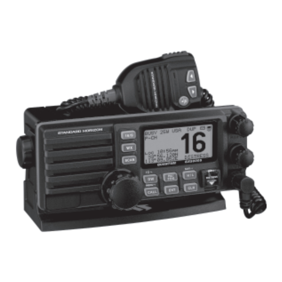
QUANTUM GX5000S
25 Watt VHF/FM
Marine Transceiver
Owner's Manual
Commercial Grade ITU Class D DSC Transceiver
Superior Receiver Performance (80 dB rejection)
30 W Loud Hailer complete with Listen Back and 4 Fog Horns, Bells,
and Whistle
Huge 2.8 inch Internal Speaker Produces Clear Load Audio
Oversized 2.8X1.4 inch Dot Matrix Display
NAV mode, Displays Latitude/Longitude, Position Time, SOG, COG
Oversized Rotary Channel Selector, Volume and Squelch Knobs
Programmable Scan, Selectable Priority Scan, and Dual Watch
One-Button Access to Channel 16 and 9
Treble and Bass Audio Tone Control
One Input for Optional RAM+ or VH-310 Remote Microphone
Optional Voice Scrambler
Plug and Play Front or Rear Panel Microphone
(optional MEK-4 extension cable available)
When attached to GPS Receiver
GX5000S
Page 1
Advertisement
Table of Contents

Related Manuals for Standard Horizon Quantum GX5000S


Summary of Contents for Standard Horizon Quantum GX5000S
- Page 1 QUANTUM GX5000S 25 Watt VHF/FM Marine Transceiver Owner's Manual Commercial Grade ITU Class D DSC Transceiver Superior Receiver Performance (80 dB rejection) 30 W Loud Hailer complete with Listen Back and 4 Fog Horns, Bells, and Whistle Huge 2.8 inch Internal Speaker Produces Clear Load Audio Oversized 2.8X1.4 inch Dot Matrix Display...
-
Page 2: Table Of Contents
TABLE OF CONTENTS GENERAL INFORMATION ........................4 INTRODUCTION .......................... 4 PACKING ..............................4 OPTIONS ..............................5 SAFETY/WARNING INFORMATION ......................5 FCC RADIO LICENSE INFORMATION ....................6 STATION LICENSE ........................6 RADIO CALL SIGN ........................6 CANADIAN SHIP STATION LICENSING ..................6 FCC / INDUSTRY CANADA INFORMATION ................ - Page 3 TABLE OF CONTENTS 11.5 INDIVIDUAL CALL ........................41 11.5.1 Setting up the Individual / Position Call Directory ..........41 11.5.2 Setting up Individual Reply ..................43 11.5.3 Setting up Individual / Group Call Ringer ............... 43 11.5.4 Transmitting an Individual Call ................44 11.5.5 Receiving an Individual Call ..................
-
Page 4: General Information
1 GENERAL INFORMATION 1.1 INTRODUCTION The STANDARD HORIZON GX5000S is a VHF/FM Marine Transceiver de- signed for use in the frequency range of 156.025 to 163.275 MHz. The GX5000S can be operated from 11 to 16 VDC and has a switchable RF output power of 1 watt or 25 watts. -
Page 5: Options
STANDARD HORIZON Web site. PRODUCT SUPPORT INQUIRIES If you have any questions or comments regarding the use of the GX5000S, you can visit the STANDARD HORIZON Web site to send an E-Mail or contact the Product Support team at 800-767-2450 M-F 7:00-5:00PST. GX5000S... -
Page 6: Fcc Radio License Information
5 FCC RADIO LICENSE INFORMATION Standard Horizon radios comply with the Federal Communication Commis- sion (FCC) requirements that regulate the Maritime Radio Service. STATION LICENSE An FCC ship station license is no longer required for any vessel traveling in U.S. waters (except Hawaii) which is under 20 meters in length. However, any... -
Page 7: Fcc Notice
Unauthorized changes or modifications to this equipment may void com- pliance with FCC Rules. Any change or modification must be approved in writing by STANDARD HORIZON. NOTICE This equipment has been tested and found to comply with the limits for a Class B digital device, pursuant to Part 15 of the FCC Rules. -
Page 8: Getting Started
7 GETTING STARTED ABOUT VHF RADIO The radio frequencies used in the VHF marine band lie between 156 and 158 MHz with some shore stations available between 161 and 163 MHz. The ma- rine VHF band provides communications over distances that are essentially “line of sight”... -
Page 9: Coaxial Cable
COAXIAL CABLE VHF antennas are connected to the transceiver by means of a coaxial cable – a shielded transmission line. Coaxial cable is specified by it’s diameter and construction. For runs less than 20 feet, RG-58/U, about 1/4 inch in diameter is a good choice. -
Page 10: Installation
8 INSTALLATION LOCATION The radio can be mounted at any angle. Choose a mounting location that: • is far enough from any compass to avoid any deviation in compass read- ing due to the speaker magnet • provides accessibility to the front panel controls •... -
Page 11: Accessory Cable
The NMEA supported sentences are: Input: GLL, GGA, RMC and GNS (RMC sentence is recommended) Output: DSC and DSE (DSC sentences to Standard Horizon Plotter for Position Polling) If you have further inquires, please feel free to contact Product Support at: Phone: (800) 767-2450 Email: marinetech@vxstdusa.com... -
Page 12: Checking Gps Connections
CHECKING GPS CONNECTIONS After connections have been made between the GX5000S and the GPS, a small satellite icon will appear on the top right corner of the LCD display. To see additional GPS information press and hold the [ H/L ( NAV )] key until the GX5000S shows the SOG and COG. -
Page 13: Changing The Time Location
CHANGING THE TIME LOCATION Set the radio show UTC time or local time with the offset inputted in section 8.5 CHANGING THE GPS TIME. 1. Press and hold down the [ CALL ( MENU )] key until “Radio Setup Radio Setup” menu appears. Radio Setup Radio Setup Radio Setup... -
Page 14: Receiver Audio Tone Control
RECEIVER AUDIO TONE CONTROL Allows the treble and bass of the speaker audio to be adjusted for the best acoustics in noisy environments. The effect is similar to adjusting the treble and bass controls on a stereo. 1. Press and hold down the [ CALL ( MENU )] key until “Radio Setup Radio Setup”... -
Page 15: Optional Mmb-84 Flush Mount Installation
OPTIONAL MMB-84 FLUSH MOUNT INSTALLATION 1. Make a rectangular template for the flush mount measuring 2.9” H x 8.1” W (72 x 205 mm). 2. Use the template to mark the location where the rectangular hole is to be cut. Confirm the space behind the dash or panel is deep enough to accom- modate the transceiver (at least 6 inches deep). -
Page 16: Optional Enhanced Ram+ Second Station Mic
8.10 OPTIONAL CMP25 ENHANCED RAM+ SECOND STATION MIC OR VH-310 HANDSET INSTALLATION The GX5000S is capable of using a CMP25 Enhanced RAM+ mic or VH-310 Handset to remotely control the Radio, DSC and PA/Fog functions. In addition the GX5000S can operate as a full function intercom system. 1. - Page 17 Remote Mic or External Speaker Selection By default the RAM+ or VH-310 Handset internal speaker is turned on, how- ever using the RAM+ mic (or VH-310 Handset) this speaker can be turned off so the external speaker can be used. RAM+ mic procedure 1.
-
Page 18: Controls And Indicators
9 CONTROLS AND INDICATORS NOTE This section defines each control of the transceiver. See Figure 4 for location of controls. For detailed operating instructions refer to chapter 10 of this manual. CONTROLS AND CONNECTIONS POWER SWITCH/VOLUME CONTROL ( VOL/PWR ) Turns the transceiver on and off as well as adjusts the audio volume. - Page 19 16/9 VOL/PWR SCAN QUANTUM GX5000S DISTRESS MENU PULL OPEN CALL Figure 4. Controls and Connectors GX5000S Page 19...
- Page 20 [ SCAN ] Key Press the [ SCAN ] key to start and stop the scanning of programmed channels. Refer to section “10.13 SCANNING” for details. Secondary use: Press and hold the [ SCAN ] key to memorizes the selected channel into the transceivers scan memory for scanning (“MEM”...
- Page 21 Adjust the PA output level while in PA/FOG mode. ACCESSORY CONNECTION CABLE Connects the GX5000S to a GPS, a PA speaker, and an external speaker. See section “3 OPTIONS” for a list of optional STANDARD HORIZON Speakers. DC INPUT CABLE...
- Page 22 FRONT PANEL REMOTE MIC Connector Connects the supplied Hand Microphone if desired. This connnector is used to remote the Front panel speaker mic using the optional MEK-4 Microphone Extension Kit. 2 front panel micro- phones to the front mic jack and the rear panel mic connector at the same time.
-
Page 23: Basic Operation
10 BASIC OPERATION 10.1 PROHIBITED COMMUNICATIONS The FCC prohibits the following communications: • False distress or emergency messages: • Messages to “any boat” except in emergencies and radio tests; • Messages to or from a vessel on land; • Transmission while on land; •... -
Page 24: Transmit Time-Out Timer (Tot)
10.4 TRANSMIT TIME - OUT TIMER ( TOT ) When the PTT switch on the microphone is held down, transmit time is limited to 5 minutes. This limits unintentional transmissions due to a stuck microphone. About 10 seconds before automatic transmitter shutdown, a warning beep will be heard from the speaker(s). -
Page 25: Noaa Weather Alert Testing
1. Program NOAA weather channels into the transceiver’s memory for scan- ning. Follow the same procedure as for regular channels under section “10.13.2 Memory Scanning ( M-SCAN ) .” 2. Press the [ SCAN ] key once to start memory scanning. 3. -
Page 26: Calling Another Vessel (Channel 16 Or 9)
8. Give your vessel’s description: length, design (power or sail), color and other distinguishing marks. The total transmission should not exceed 1 minute. 9. End the message by saying “OVER”. Release the microphone button and listen. 10. If there is no answer, repeat the above procedure. If there is still no re- sponse, try another channel. -
Page 27: Making Telephone Calls
10.10 MAKING TELEPHONE CALLS To make a radiotelephone call, use a channel designated for this purpose, The fastest way to learn which channels are used for radiotelephone traffic is to ask at a local marina. Channels available for such traffic are designated Pub- lic Correspondence channels on the channel charts in this manual. -
Page 28: Scanning
10.13 SCANNING Allows the user to select the scan type from Memory scan or Priority scan. “Memory scan” scans the channels that were programmed into memory. “Pri- ority scan” scans the channels programmed in memory with the priority chan- nel. 10.13.1 Selecting the Scan Type 1. -
Page 29: Priority Scanning (P-Scan)
10.13.3 Priority Scanning ( P-SCAN ) In the default setting, Channel 16 is set as the priority channel. You may change the priority channel to the desired channel from the Channel 16 by the Radio Setup Mode, refer to section “12.7 PRIORITY CHANNEL SET.” 1. -
Page 30: Pa/Fog Operation
The GX5000S has a 30W Hailer built-in and can be used with any 4 Ohm PA Horns. Standard Horizon offers a small and a large PA horn called the 220SW and 240SW. When in Hail mode the PA speaker Listen’s Back (acts as a mi-... -
Page 31: Operating The Fog Horn Mode
10.14.2 Operating the FOG HORN mode Operator can select from Underway, Stop, Sail, Tow, Aground, Anchor, Horn and Siren. 1. Press the [ PA/FOG ] key, then select “FOG FOG” with the CHANNEL selector knob. 2. Press the [ ENT ] key. 3. - Page 32 TYPE PATTERN USAGE UNDERWAY One 5-second blasts every 120 seconds. Motor vessel underway and making way. Listen Back 120s STOP Two 5-second blasts (separated by 2 Motor vessel underway but seconds) every 120 seconds. stopped (not making way). Listen Back 120s SAIL One 5-second blasts followed by two 1-...
-
Page 33: Display Sog And Cog Information
10.15 DISPLAY SOG AND COG INFORMATION The transceiver has the ability to display the time, SOG and COG date, as well as the vessel’s position (LAT/LON), when connected to a GPS receiver. 1. Press and hold the [ H/L ( NAV )] key to display SOG and COG information. -
Page 34: Voice Scrambler
10.17 VOICE SCRAMBLER If privacy of communications is desired, a CVS2500 4 code voice scrambler (VS) can be installed in the transceiver. Contact your Dealer to have a CVS2500 installed. Refer to the section “12.17 VOICE SCRAMBLER” to program the voice scrambler. - Page 35 MEMO GX5000S Page 35...
-
Page 36: Digital Selective Calling
11 DIGITAL SELECTIVE CALLING 11.1 GENERAL WARNING This radio is designed to generate a digital maritime distress and safety call to facilitate search and rescue. To be effective as a safety device, this equipment must be used only within communication range of a shore- based VHF marine channel 70 distress and safety watch system. -
Page 37: Programming The Mmsi
THIS NUMBER MUST BE PROGRAMMED INTO THE RADIO TO OPERATE THE GX5000S DSC FUCTIONS. How can I obtain an MMSI assignment? In the USA, visit the following websites to register: http://www.boatus.com/mmsi/ or http://seatow.com/boating_safety/mmsi.asp In the Canada, visit http://www.ic.gc.ca/epic/site/smt-gst.nsf/en/sf01032e.html or http://www.usps.org/php/mmsi/rules.php 11.2.2 Programming the MMSI WARNING A user MMSI can be inputted only once. -
Page 38: Dsc Distress Call
11.3 DSC DISTRESS CALL The GX5000S is capable of transmitting and receiving DSC Distress mes- sages to all DSC radios. The GX5000S may be connected to a GPS to also transmit the Latitude, Longitude of the vessel. 11.3.1 Transmitting a DSC Distress Call NOTE To be able to transmit a DSC distress call an MMSI number must be programmed, refer to section “11.2.2 Programming the MMSI.”... - Page 39 Transmitting a DSC Distress Alert with Nature of Distress The GX5000S is capable of transmitting a DSC Distress Alert with the follow- ing “Nature of Distress” categories: Undesignated, Fire, Flooding, Collision, Grounding, Capsizing, Sinking, Adrift, Abandoning, Piracy, MOB 1. Lift the red spring loaded DISTRESS cover and press the [DISTRESS] key.
-
Page 40: Receiving A Dsc Distress Call
11.3.2 Receiving a DSC Distress Call 1. When a DSC Distress call is received, an emergency alarm sounds. Then channel 16 is automatically selected. 2. Press any key to stop the alarm. 3. The LCD shows the position of the vessel in distress. If the position of the vessel distress data does not include position, the LCD will show the display on the right. -
Page 41: Receiving An All Ships Call
type of all ships DSC call. 6. After the All Ships Call is transmitted, the transceiver will switch to CH16. 7. Listen to the channel to make sure it is not busy, then key the microphone and say PAN PAN PAN or “Securite, Securite, Securite”... - Page 42 5. Select “Add Add” with the CHANNEL selector knob, then press the [ ENT ] key. 6. Turn the CHANNEL selector knob to scroll through the first letter of the name of the vessel or person you want to reference in the directory. 7.
-
Page 43: Setting Up Individual Reply
11.5.2 Setting up Individual Reply Allows setting up the radio to automatically (default setting) or manually re- spond to a DSC Individual call requesting you to switch to a working channel for voice communications. When Manual is selected the MMSI of the calling vessel is shown allowing you to see who is calling. -
Page 44: Transmitting An Individual Call
The GX5000S has the capability to turn off the Individual call ringer. 1. Press and hold down the [ CALL ( MENU )] key until “Radio Setup Radio Setup” menu appears. Radio Setup Radio Setup Radio Setup 2. Turn the CHANNEL selector knob to select “DSC Setup DSC Setup”... - Page 45 7. When an individual call acknowledgment is re- ceived, the established channel is automatically changed to the channel which is selected on step 5 above and a ringing tone sounds. 8. Press [ CLR ] key to listen to the channel to make sure it is not busy, then key the microphone and call the other vessel you desire to com- municate with.
-
Page 46: Receiving An Individual Call
11. When an individual call acknowledgment is re- ceived, the established channel is automatically changed to the channel which is selected on step 5 above and a ringing tone sounds. 12. Press the [ CLR ] key to listen to the channel to make sure it is not busy, then key the micro- phone and call the other vessel you desire to communicate with. -
Page 47: Reviewing Received Calls Logged Into The Call Waiting Directory
6. Press the [ ENT ] key to store the selected setting. 7. Press the [ CLR ] key twice to return to the “Radio Radio Radio Radio Radio Setup” menu, then press the [ CLR ] key again to re- Setup Setup Setup... -
Page 48: Group Call
MMSI numbers. The first digit of a Group MMSI is always set to “0” by International rules. All Standard Horizon radios are preset so when programming a Group MMSI the first digit is set to “0”. -
Page 49: Transmitting A Group Call
6. Turn the CHANNEL selector knob to scroll through the first letter of the name of the group you want to reference in the directory. 7. Press the [ ENT ] key to store the first letter in the name. 8. - Page 50 to communicate on and press the [ ENT ] key. 6. Press the [ ENT ] key again to transmit the Group Call signal. 7. When the Group Call signal is sent, the LCD will be as shown in the illustration at the right. 8.
-
Page 51: Receiving A Group Call
10. Press the [ ENT ] key again to transmit the Group Call signal. 11. After the GROUP CALL is transmitted, all the radios in the group will switch to the designated channel. 12. Listen to the channel to make sure it is not busy, then key the microphone and call the other vessels you desire to communicate with. -
Page 52: Position Request
GX5000S. Standard Horizon has taken this feature one step further, if any Standard Hori- zon GPS is connected to the GX5000S, the polled position of the vessel is shown on the display of the GPS chart plotter making it easy to navigate to the location of the polled vessel. -
Page 53: Transmitting A Position Request To Another Vessel
11.8.2 Transmitting a Position Request to Another Vessel Pre-Programmable Request 1. Press the [ CALL ( MENU )] key. The “DSC Call DSC Call DSC Call DSC Call DSC Call Menu” will appear in the display. Menu Menu Menu Menu 2. -
Page 54: Receiving A Position Request
6. If a mistake was made entering in the MMSI num- ber repeat pressing the [ H/L ( NAV )] key until the wrong number is selected, then turn the CHANNEL selector knob to correct the entry. 7. When finished entering the MMSI number, press and hold the [ ENT ] key. -
Page 55: Position Send
11.9 POSITION SEND The feature is similar to Position Request, however instead of requesting a position of another vessel this function allows you to send your position to another vessel. Your vessel must have an operating GPS receiver connected for the GX5000S to send the position. NOTE To transmit a Position Send Call, you must setup the GX5000S DSC Individual / Position Call Directory with the name of the vessel(s) or... - Page 56 tory.” This directory uses the “Individual Direc- tory” information. 4. Turn the CHANNEL selector knob to select a name in the directory, then press the [ ENT ] key. 5. Press the [ ENT ] key again to send your posi- tion to the selected vessel.
-
Page 57: Receiving A Dsc Position Send Call
3. The position from the vessel sending it's position will be shown on the display of the radio and also transferred to any Standard Horizon GPS Chart plot- ter if connected. 11.10 MANUAL INPUTTING OF THE GPS LOCATION ( LAT/LON ) You may send the Latitude/Longitude of your vessel manually even if the GX5000S is not connected the GPS receiver unit. -
Page 58: Radio Setup Mode
12 RADIO SETUP NOTE The optional CMP25 RAM+ MIC and VH-310 Handset can also change the SETUP menu. Refer to page 75 (CMP25) and page 85 (VH-310) for details. 12.1 LAMP ADJUSTING Allows setting up the backlight intensity or to turn it off. 1. -
Page 59: Time Offset
12.3 TIME OFFSET Sets the time offset between local time and UTC shown on the display. Time is displayed when the GPS unit (not supplied) is connected. 1. Press and hold down the [ CALL ( MENU )] key until “Radio Setup Radio Setup”... -
Page 60: Time Display
12.4 TIME DISPLAY Allows the time shown on the display to be shown in local or UTC time. Time is displayed when the GPS unit (not supplied) is connected. 1. Press and hold down the [ CALL ( MENU )] key until “Radio Setup Radio Setup”... -
Page 61: True Magnetic Change (Nav Display)
12.6 TRUE MAGNETIC CHANGE ( NAV DISPLAY ) This selection allows customizing the GPS COG (Course Over Ground) dis- played on the LCD to be in True or Magnetic. 1. Press and hold down the [ CALL ( MENU )] key until “Radio Setup Radio Setup”... -
Page 62: Scan Type
12.8 SCAN TYPE This selection is used to select the scan mode between “Memory Scan” and “Priority Scan.” 1. Press and hold down the [ CALL ( MENU )] key until “Radio Setup Radio Setup” menu appears. Radio Setup Radio Setup Radio Setup 2. -
Page 63: Key Beep (On / Off)
12.10 KEY BEEP ( ON/OFF ) This selection is used to select the beep tone volume lebel when a key is pressed. 1. Press and hold down the [ CALL ( MENU )] key until “Radio Setup Radio Setup” menu appears. Radio Setup Radio Setup Radio Setup... -
Page 64: Channel Naming
12.12 CHANNEL NAMING This selection allows you to customize the name of a channel from the default name. Example: CH69 PLEASURE to HOOKUP 1. Press and hold down the [ CALL ( MENU )] key until “Radio Setup Radio Setup” menu appears. Radio Setup Radio Setup Radio Setup... -
Page 65: Receiver Audio Tone Control
the [ ENT ] key. 5. Turn the CHANNEL selector knob to scroll through the first letter of the unit name. 6. Press the [ ENT ] key to store the first letter in the name and step to the next letter to the right. 7. -
Page 66: Fog Alert Tone Frequency
12.15 FOG ALERT TONE FREQUENCY This selection allows you to select the Tone Frequency for the PA/FOG Opera- tion. Available selections are “200Hz” through “850Hz” in 50Hz steps. The default Tone Frequency is 400Hz. 1. Press and hold down the [ CALL ( MENU )] key until “Radio Setup Radio Setup”... -
Page 67: Calendar Setup
12.16 CALENDAR SETUP Calendar Menu The GX5000S has a built in clock to remember date, time, latitude and longi- tude. Connecting a GPS to the GX5000S is very important as it not only will be used to update the calendar automatically and also when a DSC Distress call is transmitted will send your vessels location to other vessels to aid in the rescue. - Page 68 Examples: NOTE If you are west of UTC time you will add the offset to your time. If you are East of UTC time you will subtract the offset from your time. City Los Angeles Offset Time (convert local time to 24 hour) 4:00PM (local) or 16:00 (24hour) Calculate 24hour local + Offset (East of UTC) 16:00 + 08:00 = 23:00...
-
Page 69: Voice Scrambler
11. Select "Update Update" with the CHANNEL selec- tor knob, then press the [ ENT ] key. 12. Turn the CHANNEL selector knob to select the method of the time adjustment between “Automatic Automatic Automatic” Automatic Automatic and “Manual Manual Manual Manual.”... -
Page 70: Enhanced Ram+ Mic Operation
RAM+ Mic and the transceiver. In addition, speaker wires are supplied at the panel mount of the routing cable allowing the STANDARD HORIZON MLS-300 or MLS-310 External speakers to be con- nected in noisey environments. - Page 71 POWER SWITCH ( PWR ) Press and hold down this key to turn to the transceiver and RAM+ Mic on or off. PTT ( Push-To-Talk ) SWITCH Activates transmission. [ H/L ] KEY Toggles between high and low power. When the [ H/L ] key is pressed while the transceiver is on channel 13 or 67, the power will temporarily switch from LO to HI power until the PTT is released.
- Page 72 [ DW ( IC )] Key Watches for a transmission on CH16 and another selected channel until either signal is received. (Dual watch) Secondary use Press and hold [ DW ( IC )] key, intercom operation will operate between radio and RAM Mic. [ NAV ] Key Press this key, when connected to the GPS receiver to show GPS position data (Lat/Lon) and Time on the display of the RAM+.
-
Page 73: Intercom Operation
RECEIVED ACK: acknowledgment signal is received. RECEIVED RLY: relay signal is received from another vessel or coast station. 6. To cancel the DSC distress alarm signal from the speaker, press any key. 13.2 INTERCOM OPERATION 13.2.1 Communication 1. Press and hold the [ DW ( IC )] key while in the “RADIO” mode, the mode is changed to “INTERCOM”... -
Page 74: Pa/Fog Operation
13.3 PA/FOG OPERATION When the RAM+ is connected to the GX5000S it is capable of controlling the 30W Public address, 4 fog horns, bells, and whistles. 13.3.1 Operating the PA / Hailer 1. Press and hold the [ NAV ] key then select PA with the [ ] or [ ] key. -
Page 75: Dsc/Radio Setup Mode
13.4 DSC/RADIO SETUP MODE The RAM+ can access the DSC / RADIO setup menu (refer to section “11 DIGITAL SELECTIVE CALLING” and section “12 RADIO SETUP MODE” for details). However, the LAMP, CONTRAST, and KEY BEEP menu item which is accessed from the RAM+ only controls the RAM+’s display and speaker. -
Page 76: Changing Gps Information To Vessel Position Or Cog
13.4.1 Changing GPS Information to Vessel Position or COG Factory default is “Your Vessel’s Current Position,” however, following the steps below the GPS Information can be changed to “Course Over Ground (COG).” 1. Press and hold down the [ CALL ( ENT )] key until “RADIO RADIO RADIO RADIO... - Page 77 MEMO GX5000S Page 77...
-
Page 78: Handset Opertion
CT-100. The intercom operation can be used between the VH-310 HANDSET or the GX5000S. In addition, speaker wires are supplied at the panel mount of the routing cable allowing the STANDARD HORIZON MLS- 300 or MLS-310 External speakers to be connected in noisey environments 14.1 VH-310 HANDSET CONTROLS... - Page 79 [ SQL ] key Activates the squelch adjusting mode. Press this key to activate the squelch adjusting mode. Press the [ ] or [ ] key to adjust the squelch. [ CALL ( MENU )] key The [ CALL ( MENU )] key functions as the enter key. Secondary use Press the [ CALL ( MENU )] key to access the DSC OPERATION menu.
- Page 80 KEYPAD [ 1 ( DIM )] key When in radio mode, this key is used to directly select digit “1” in a channel number. Secondary use Press the [ F ] key first then press the [ 1 ( DIM )] key to access the LCD Dimmer menu.
- Page 81 [ 6 ( NAV )] Key When in radio mode, this key is used to directly select digit “6” in a channel number. Secondary use Press the [ F ] key first then press the [ 6 ( NAV )] key, the LCD will display NAV GPS Data, Time, SOG (Speed Over Ground), and COG (Course Over Ground) when a GPS is connected to the accessory cable of the GX5000S.
-
Page 82: Intercom Opertion
14.2 INTERCOM OPERATION 14.2.1 Communication 1. Press the [ F ] key followed by the [ 5 ( IC )] key, the mode is changed to “IN- TERCOM” mode. 2. When the “INTERCOM” operation is activated, “IC” is dis- played on the VH-310 Handset (and RAM+ Mic, if used) and “INTERCOM”... -
Page 83: Pa/Fog Operation
14.3 PA/FOG OPERATION The VH-310 Handset is capable of controlling the 30W Public address, 4 fog horns, bells and whistles. 14.3.1 Operating the PA / Hailer 1. Press the [ F ] key followed by the [ 8 ( PA )] key, activate the “PA / HAIL”... -
Page 84: Manual Inputting Of The Gps Location (Lat/Lon)
14.4 MANUAL INPUTTING OF THE GPS LOCATION ( LAT/LON ) You may send the Latitude/Longitude of your vessel manually from the VH- 310 Handset even if the GX5000S is not connected the GPS receiver unit. After the position is entered, transmitting a DSC Distress, Position Request, or Position Send will contain the manually entered position. -
Page 85: Dsc/Radio Setup Mode
14.5 DSC/RADIO SETUP MODE The VH-310 Handset can access the DSC / RADIO setup menu (refer to sec- tion “11 DIGITAL SELECTIVE CALLING” and section “12 RADIO SETUP MODE” for details). The CONTRAST KEY BEEP, and AF SELECT CONTRAST CONTRAST CONTRAST, NAV DISPLAY NAV DISPLAY NAV DISPLAY... -
Page 86: Changing Gps Information To Vessel Position Or Cog
AF SELECT External Speaker to a fixed level regardress of the VOL level setting of the VH- 310, which is useful when using the STANDARD HORIZON MLS-310 10W amplified speaker with on/off volume control. 1. Press and hold down the [ CALL ( MENU )] key until “Radio... - Page 87 MEMO GX5000S Page 87...
-
Page 88: Maintenance
11 VDC. • Use only STANDARD HORIZON-approved accessories and replacement parts. In the unlikely event of serious problems, please contact your Dealer or our repair facility. Address and phone numbers for this facility, as well as warranty informa- tion, are contained in section “17 WARRANTY.”... -
Page 89: Troubleshooting Chart
15.3 TROUBLESHOOTING CHART SYMPTOM PROBABLE CAUSE REMEDY Transceiver fails to No DC voltage to the a. Check the 12VDC battery connections and power up. transceiver, or blown the fuse. fuse. b. The VOL/PWR knob needs to be pressed and held to turn the radio on. Transceiver blows fuse R e v e r s e d p o w e r Check the power cable for DC voltage, or re-... -
Page 90: Channel Assignments
16 CHANNEL ASSIGNMENTS Tables on the following columns list the VHF Marine Channel assignments for U.S.A. and International use. Below are listed some data about the charts. 1. VTS. Where indicated, these channels are part of the U.S. Coast Guard’s Vessel Traffic System. - Page 91 VHF MARINE CHANNEL CHART CHANNEL USE D 156.050 160.650 Public Correspondence (Marine Operator) 156.050 Port Operation and Commercial. VTS in selected areas D 156.100 160.700 Public Correspondence (Marine Operator) D 156.150 160.750 Public Correspondence (Marine Operator) 156.150 U.S. Government Only, Coast Guard D 156.200 160.800 Public Correspondence (Marine Operator), Port operation, ship movement 156.200...
- Page 92 VHF MARINE CHANNEL CHART CHANNEL USE D 156.025 160.625 Public Correspondence (Marine Operator) D 156.075 160.675 Public Correspondence (Marine Operator), Port operation, ship movement 156.075 Public Coast: Coast Guard; East Coast: commercial fishing only D 156.125 160.725 Public Correspondence (Marine Operator), Port operation, ship movement 156.125 Public Coast: Coast Guard;...
- Page 93 VHF MARINE CHANNEL CHART CHANNEL USE D 157.025 161.625 Port operation, ship movement 157.025 Commercial D 157.075 161.675 Port operation, ship movement 157.075 U.S. Government Only - Environmental protection operations. 157.075 Canadian Coast Guard Only D 157.125 161.725 Public Correspondence (Marine Operator), Port operation, ship movement 157.125 U.S.
- Page 94 Points of communica- Points of communica- Carrier frequency Carrier frequency tion (Intership and be- tion (Intership and be- ( MHz ) ( MHz ) Channel Channel tween coast and ship tween coast and ship designator designator Coast Coast Ship Ship u n l e s s o t h e r w i s e u n l e s s o t h e r w i s e transmit...
- Page 95 4: Use of 156.875 MHz is limited to communications with pilots regarding the movement and docking of ships. Normal output power must not exceed 1 watt. 5: 156.375 MHz and 156.650 MHz are available primarily for intership navigational com- munications. These frequencies are available between coast and ship on a secondary basis when used on or in the vicinity of locks or drawbridges.
-
Page 96: Warranty
Boards. To receive warranty service, the purchaser must deliver the Product, transpor- tation and insurance prepaid, to STANDARD HORIZON (a division of VER- TEX STANDARD), Attention Marine repairs 10900 Walker Street, Cypress, CA 90630. Include proof of purchase indicating model. serial number, and date of purchase. - Page 97 Products on which the serial number has been removed, defaced, or changed. STANDARD HORIZON cannot be responsible in any way for ancillary equip- ment not furnished by STANDARD HORIZON which is attached to or used in connection with STANDARD HORIZON’s Products, or for the operation of the Product with any ancillary equipment, and all such equipment is expressly excluded from this warranty.
- Page 98 If you wish to obtain the flat rate price for out-of-war- ranty repair, you must include the information on the Owner’s Record with the unit when you return it to your Dealer or to STANDARD HORIZON. Lifetime Flat Rate Service Program: For the original Owner only, for the lifetime of the unit, STANDARD HORIZON will repair the unit to original specifications.
-
Page 99: Specifications
18 SPECIFICATIONS Performance specifications are nominal, unless otherwise indicated, and are subject to change without notice. 18.1 GENERAL Channels ..........All USA, International and Canadian Input Voltage ................. 13.8 VDC ±20% Current Drain Standby ..................... 0.5 A Receive ..................... 1.5 A Transmit .............. - Page 100 Copyright 2009 VERTEX STANDARD CO., LTD. All rights reserved. Marine Division of VERTEX STANDARD US Headquarters No portion of this manual 10900 Walker Street, Cypress, CA 90630, U.S.A. may be reproduced www. standardhorizon.com without the permission of VERTEX STANDARD CO., LTD. Page 100 GX5000S...
Need help?
Do you have a question about the Quantum GX5000S and is the answer not in the manual?
Questions and answers