Table of Contents
Advertisement
Quick Links
Advertisement
Table of Contents

Related Manuals for Intelbras AMT 8000 Slim


Summary of Contents for Intelbras AMT 8000 Slim
- Page 1 Installation/user guide AMT 8000 Slim...
- Page 2 Congratulations, you have just purchased a product with Intelbras quality and safety. The AMT 8000 SLIM alarm system is a solution against intrusion. Composed by the AMT 8000 alarm panel, XSS 8000 siren, XAC 8000 remote control, IVP 8000 PET motion sensor and XAS 8000 aperture sensor, offers protection with maximum security.
-
Page 3: Table Of Contents
Índice AMT 8000 - Alarm center 1. Technical Specifications 2. AMT 8000 Alarm Center Features 3. AMT 8000 Accessories 3.1. GPRS XAG 8000 Module and GSM XAG 8000 3G Module ..........9 3.2. - Page 4 6.13. Alarm Center Time Settings ..............53 6.14.
- Page 5 IVP 8000 PET - Infrared passive sensor 1. Care and security 1.1. Scan (upper view) ............... .113 1.2.
-
Page 6: Amt 8000 Alarm Center
Reports events to 2 IP destinations (monitoring companies). The center is already directed to the Intelbras Cloud using initially the random remote access password indicated along with the QR Code label that also contains the MAC. - Page 7 » Perform periodic tests on it in order to validate weather conditions, battery level and other factors, so that the site super- vised by the system is always able to operate correctly. » LGPD - General Law for the Protection of Personal Data: this product handles personal data, but Intelbras does not » has access to data from this product.
-
Page 8: Technical Specifications
( Stand by - continuous mode). ² Optional: for more information see the website www.intelbras.com.br. Attention: Intelbras wireless systems are tested to the highest standards and bring high reliability, however, due to their use/installation in various scenarios, some considerations must be taken into account: »... -
Page 9: Amt 8000 Accessories
» 2G GPRS communication with the XAG 8000 module and 2G / 3G communication with the XAG 8000 3G module. » External antenna with 0 dBi gain. » Reports events to 2 IP destinations (monitoring company) plus the Intelbras cloud. » Operates with fixed or dynamic IP. -
Page 10: Communication Module Via Telephone Line - Fxo 8000
Note: the XAG 8000 and XAG 8000 3G modules are compatible with most national GPRS / GSM operators with 2G and 3G technology and can only be used with the AMT 8000 alarm panel. 3.2. Communication module via telephone line - FXO 8000 Optional accessory dedicated to data transmission via telephone line for communication and event reporting to a monitoring company with the AMT 8000 security system, in addition to dialing up to 5 personal phones and emitting the sound of a siren from the telephone line. -
Page 11: Xac 8000 Remote Control
» Sound signalling during operation. » DC Power: 4 batteries 3 Vdc (CR2450) included. » Communication supervision and encrypted transmission. » Range: up to 600 m with direct view in open field. The following figure shows the illustrative image of the keyboard: XAT 8000 Wireless Keyboard The keyboard has two tamper keys, one of which is located on the front of the keyboard, under the cover, is activated by moving the keyboard cover, its function is to activate the keyboard and the other key, located on the back of the keyboard... -
Page 12: Wireless Siren - Xss 8000
3.5. Wireless siren - XSS 8000 Optional dedicated accessory for status audible warning, intrusion and emergency indications from the AMT 8000 alarm center. Communication between the siren and the center is made through a wireless signal, providing a simpler installation and long communication range. -
Page 13: Passive Infrared Wireless Sensor - Ivp 8000 Pet
The following figure shows the illustrative image of the XAS 8000 sensor: XAS 8000 aperture sensor XAS 8000 sensor has a tamper key against violation, and if this key is opened/violated, registered sirens will trigger and send the corresponding event if the Problems that generate trigger function is enabled (Problems that generate trigger). The status of the sensor communication with the alarm center will be represented on it through the indicator LED located on the front, and when in normal communication the LED will flash green, with partial communication orange and no communication red (the indicator LED after 15 minutes will enter hibernation mode for battery saving, not hindering the... -
Page 14: Passive Infrared Wireless Sensor - Ivp 8000 Pet Cam
IVP 8000 Pet sensor has a tamper key against violation, and if this key is opened/violated, registered sirens will trigger and send the corresponding event if the Problems that generate trigger function is enabled (see section Problemas que geram disparo ). The status of the sensor communication with the alarm center will be represented on it through the indicator LED located on the front, and when in normal communication the LED will flash green, with partial communication orange and no communication red (the indicator LED after 15 minutes will enter hibernation mode for battery saving, not hindering the device communication and to activate again press the device synchronisation key once). - Page 15 Features: » Wireless communication with the alarm center (915 to 928 MHz) via internal antenna, power 11 dBm. » Communication status check through LED. » Fastening by screws (not included) or double-sided tape (not included). » DC Power Supply: 1 CR2450 type 3 Vdc battery of long life lithium. »...
-
Page 16: Installation Of The Alarm Center And Its Peripherals
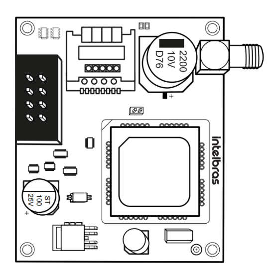
The following figure shows the illustrative image of the repeater: Range RF Amplifier (REP 8000 Repeater) Range RF Amplifier (REP 8000 Repeater) has a tamper key against violation, located at the back of the repeater, and if this key is opened/violated, registered sirens will trigger and send the corresponding event if the Problems that generate trigger function is enabled (see the Problems that generate trigger section). - Page 17 Image below illustrates the alarm center with all the devices that can be physically connected: AMT8000 AMT 8000 Alarm Center 1. Connector for network cable (Ethernet). 2. CPU card of the AMT 8000 alarm center. 3. Mini-USB type connector for alarm center firmware update. 4.
-
Page 18: Power Supply For The Alarm Center (Full Range 90 And 265 Vac)
Attention: the AMT 8000 alarm center does not have an auxiliary output to feed other devices and no connection point must be used on the alarm center cards (alarm center, GPRS card, telephone line card or source) for this functionality, because besides damaging the alarm center, it may damage the devices due to the alarm center operating at different voltages according to the circuit. -
Page 19: Xag 8000 Gprs Module
Alarm center has protection against reverse polarity and short circuit in the battery. The unit also has protection to prevent the battery from being damaged in the event of a mains failure. If the voltage in the battery is below 2.8 V, the alarm center will switch off in order not to damage the battery. Battery life of 8 hours with Wi-Fi enabled and 16 hours with Wi-Fi disabled. -
Page 20: Operation
Alarm center can be installed on several surfaces, always placing it in a vertical position with a height between 1.80 and 2.20 meters and using double-sided tape or screws (not included) to fix the base and after securing the alarm center, fitting and checking that it has been placed correctly so that there are no falls and damage, and directing the wires in the dedicated areas. -
Page 21: Partitioning
5.4. Partitioning Using this feature through alarm center programming you can split it into up to 16 independently activated and deactivated partitions and associate any of the 64 wireless zones with any of the partitions. You can also program passwords giving specific permissions to these partitions. - Page 22 Activation by a key If the One Key Activation function is enabled (see section General settings 1 ), keeping the active key pressed until the keyboard beeps ( + /- 3 seconds) will activate the system in Full mode. Exit time will be initiated to exit the protected area. At the end of the exit time, the system will be activated in Full mode (all partitions).
-
Page 23: Menu
The zones, which must be passed until the keyboard is reached, must be programmed as entry timers or as followers so that the alarm not to be triggered immediately when the keyboard access path is violated/accessed. After entering the protected area by an entry time zone, the entry time will start and the user must enter a valid password on the keyboard before the time limit ends, to avoid triggering the alarm and reporting the corresponding events. - Page 24 Refer to the Connections section for setting priority addresses and directions. » Cloud: Will display whether the center is connected to the Intelbras Cloud server via ETHERNET (network cable), via WI- FI or 2G / 3G. This server allows communication between AMT 8000 and remote access via application.
- Page 25 2G/3G signal It will display the operator’s signal level in percent, where square 1 represents level less than or equal to 10% and square 0 represents 100%. The filled mark corresponds to the active sign and the empty mark to the one without sign, referring to the level in 10 divisions.
-
Page 26: Remote Update
Test mode It will perform the wireless signal test of the keyboard used with the registered center. When pressing Menu , with the arrow keys leave the marker in Test mode and press Enter . The test will start, showing the Signal test information and at the end the result, which can be Excellent, Good, Weak or No response in case of loss of communication with the alarm center. - Page 27 » If the keyboard is left unoperated for three minutes, the alarm center exits programming mode and when accessed the keyboard is directed to the home screen. » There is no need to exit the programming mode to execute the next command allowed by the password. Direct editing/programming command In programming mode, the command will be inserted by directly typing its entire extension and at the end pressing Enter to save the command and proceed to another, for example:...
-
Page 28: Wireless Devices (Register/Delete)
Note: it is required that the computer/remote access password is enabled, see 6.8. Passwords section. Using Intelbras Guardian application (for mobile devices) Through the application installed on a mobile device (smartphone/tablet – Android /iOS) you can access the alarm center ®... - Page 29 Table below shows how many and which wireless devices can be registered in the alarm center. Types of devices Maximum devices Addresses Keyboards XAT 8000 01 to 16 Controls XAC 8000 00 to 97 XAS 8000 Sensors IVP 8000 Pet 01 to 64 TX 8000 Sensor with photochecking...
- Page 30 » Wireless sensors (addresses 01 to 64): follows the same principle as the other devices, however each sensor will be associated to a zone of the alarm center according to the registration sequence, starting with sensor 01 (corresponds to zone 01) up to sensor 64 (corresponds to zone 64). With the function active in the alarm center, press the synchronization key on each sensor that you want to synchronize according to its models: »...
- Page 31 To delete wireless keyboards, type: 01 to 16 Enter Keyboard N° Enter Note: After registering the keyboard it will go into the process of updating messages, which takes approximately 30 seconds per keyboard and occurs in one keyboard at a time. If the message update process is interrupted, the keyboard will update them again as soon as it is opened again.
- Page 32 To register wireless sirens, type: 01 to 16 Enter Siren N° Enter Activate the wireless device To delete wireless sirens, type: 01 to 16 Enter Siren N° Enter » Range RF Amplifier (REP 8000 repeater, addresses 01 to 04): follows the same principle as other devices. It is necessary to press the synchronization key on the back of the repeater (remove the base to fix it on surfaces and turn on the power supply of the repeater, because for it to initialize the source must be on), after typing the following code, check if the LED will flash green, indicating the success of the registration.
-
Page 33: Wireless Sensor Functions
Ex: sensor 01 communicating with the repeater 01: Reset wireless devices It will erase all registered wireless devices, including the keyboard used to perform the command. If you wish to re-register any device after the reset, it will be necessary to physically delete it by the synchronization key and only after confirmation of its deletion, by LED indication, it will be possible to re-register it. -
Page 34: Functions Of Remote Control Keys
Example of a test with sensor 01 of non-partitioned alarm center: » 1 line of the display: Localized P00 message will be displayed » 2 line of the display: Sensor 01 message will be displayed Note: For partitioned system you will see P00 for common partition or P01 to P16 according to which partition the device belongs. - Page 35 Disabled Atv/Dtv all partitions Only activates all partitions Only deactivates all partitions Atv/Dtv all partitions in Partial mode (stay) Arm only in Partial mode (stay) Panic with siren Silent panic Fire panic Medical emergency Atv/Dtv only Partition 1 Atv/Dtv only Partition 2 Atv/Dtv only Partition 3 Atv/Dtv only Partition 4 Atv/Dtv only Partition 5...
-
Page 36: Functions Of Wireless Keyboard
To program this function, type: Enter Control key User Function Enter Table above 1, 2 or 3 00 to 97 From 00 to 46 To edit/view the programmed value, type: Enter Control key User Enter After changing the configured value, press the Enter key. If you only want to view the setting, press the Exit key and no programming will be changed. - Page 37 Predefined messages are as follows: Function Description Activation Alarm center has been activated Deactivation Alarm center has been deactivated Trigger Trigger The second line will indicate which zone 24 Hour Trip Trip a zone 24 hours. The second line will indicate which zone Panic Panic triggers.
-
Page 38: Siren Functions
To program this function, type: Enter Selection Enter 0 to 4 table above To edit/view the programmed value, type: Enter Enter After entering the command, define which function will have the Panic key, being the selection 0 as disabled, 1 as Audible Panic (factory default), 2 as silent panic, 3 as fire panic and 4 as medical emergency and press the Enter key to confirm. - Page 39 Use key 3 on the keyboard to enable the siren beep on activation/deactivation of the system, so that the number 3 remains selected to enable and deselected to disable the siren beep and then confirm with the Enter key. If you only want to view the setting, press the Back/Exit key that no programming will be changed.
-
Page 40: Update
6.7. Update AMT 8000 alarm center has remote software updates, and if new software versions are available, it is not necessary to use recorders or connect to computers to be updated by downloading the new version through Ethernet or Wi-Fi connections. When the version update is performed, the registration of the wireless devices or saved settings will not be lost. - Page 41 Programming password permissions Password Enabling Create and delete secondary passwords Change the master password Master (initially Enable/disable secondary password permissions random, see QR Code Adjust date, time and day of week label) Editing XAT 8000 keyboard messages Activate/deactivate the center completely or partitioned (Partition 01 to 16) Installer (factory Perform all settings of the alarm center, except enable/disable the center, default password:...
- Page 42 User User User Users of Users of Users of group group group 61 to 70 71 to 80 81 to 90 (GU) (GU) (GU) Key 1 = user 61 Key 1 = user 71 Key 1 = user 81 Key 2 = user 62 Key 2 = user 72 Key 2 = user 82 Key 3 = user 63...
- Page 43 To program this function, type: Enter User Password Enter 00 to 97 4 or 6 digits Delete the passwords using the master password The master user password - 00 can only be changed and not deleted. User passwords 01 to 97 can be deleted. To program this function, type: Enter User...
-
Page 44: Quick Setup For Sms Monitoring And Programming
Installer password (factory standard: 9090 ). Monitoring via Ethernet/Wi-Fi The alarm center can report events via IP communication to monitoring companies (Software Receptor IP Intelbras), for this the following commands must be programmed: If you are using the Wi-Fi connection before you set the monitoring options, program the following commands: Note: the alarm center connects only with 2.4GHz routers. - Page 45 » Insert name of Wi-Fi network to be connected Enter + 850 + Enter + Insert network name + Enter » Insert password of Wi-Fi network to be connected Enter + 851 + Enter + Insert network password + Enter »...
- Page 46 » Programming the network mask Enter + 8130 + Enter After the command, enter the network mask number and press the Enter key to confirm. » Programming the gateway Enter + 8140 + Enter After the command, enter the network gateway number and press the Enter key to confirm. »...
- Page 47 After the command, using the keys on the keyboard, enable the desired option from 1 to 4, where: » 1: enables the sending of events to the monitoring company 1. » 2: enables the sending of events to the monitoring company 2. »...
-
Page 48: Zone Settings
» Program GPRS channel options to enable chips and SMS sending/receiving Enter + 832 + Enter After the command, use the keys on the keyboard to enable 1 (chip 1), 2 (chip 2), 3 (send SMS), 4 (receive SMS) options and press the Enter key to confirm. - Page 49 To program this function, type: From 0 to 6 Enter Zone group Enter Use the keys on the keyboard to define the status of the zone, so that the numbers that you wish to have the zone active remain marked and the zones that should remain inactive remain unchecked, then confirm with the Enter key. Note: All zones leave the factory enabled.
- Page 50 To program this function, type: From 1 to 6 From 0 to 6 Enter Zone Functions Zone group Enter Zone Functions Timed Follower 24 Hour Panic Medical emergency Fire Use the keys on the keyboard to define the function of the zone, so that the numbers that you want to have the zone with the given function remain marked and the zones without the function remain unchecked, then confirm with the Enter key.
-
Page 51: Programming The Alarm Center Partitioning
After changing the configured value, press the Enter key. If you only want to view the setting, press the Back/Exit key that no programming will be changed. 6.11. Programming the alarm center partitioning Enable partitioning To enable alarm center partitioning (the center can have up to 16 partitions with independent activation/deactivation and event reporting), it must be programmed: Enter Enter... -
Page 52: Timings
Attention: besides the above mentioned programming points, user passwords must be created/defined (topic Passwords ) besides registering wireless controls for access (topic Remote controller ) and also define partitioning of keyboards (topic Keyboard ) and sirens (topic Wireless sirens ). To edit/view the programmed value, type: Enter User number... - Page 53 The output timing is valid only for activation of the unit via keyboard. When activation is done via remote control the timing will always be zero (instantaneous). On non-partitioned systems, program the output time with the partition address being 01 . To program this function, type: 000 to 255 seconds Enter...
- Page 54 Time interval for date and time synchronization When this function is enabled, the alarm center will synchronize the date and time with the server where the Intelbras IP Receiver software is installed (24 hour factory standard synchronization), for third party software they should be consulted.
- Page 55 To edit/view the programmed value, type: Enter Enter After changing the configured value, press the Enter key. If you only want to view the setting, press the Exit key and no programming will be changed. 6.14. Periodic Test This function is used to check the integrity of the communication channel between the alarm center and the monitoring company.
- Page 56 4. Adjust the system date and time; 5. Adjust the day of the week; 6. If you want to enable automatic time and date synchronization with the server (make sure you are using the latest version of Intelbras IP Receiver for the correct effect).
- Page 57 Use the table below for the following required settings: Weekday Key 1 Sunday Key 2 Monday Key 3 Tuesday Key 4 Wednesday Key 5 Thursday Key 6 Friday Key 7 Saturday Key 8 Holiday Selecting Autoactivation and Autodeactivation by Partitions Selects which partitions will have the autoactivation and autodeactivation function programmed.
- Page 58 To edit/view the programmed value, type: 1 to 8 Enter Partition Enter 01 to 16 After changing the configured value, press the Enter key. If you only want to view the setting, press the Back/Exit key that no programming will be changed. Weekdays for Autodeactivation Select the days on which Partition Autodeactivation will occur.
- Page 59 » Days for programmed autoactivation. » Time for programmed autoactivation. » Days for programmed autodeactivation. » Time for programmed autodeactivation. » Weekday adjustment » Time interval for date and time synchronization. Set holidays for Autodeactivation/Autodeactivation. If the center is partitioned, holidays can be defined per partition. To program this function type: 0 to 9 Enter...
- Page 60 Event Standard code Medical emergency Fire alarm Panic Activation and deactivation under duress Silent panic Zone triggering/Zone restoration 24 hour zone triggering Silent triggering AC mains failure/AC mains restoration Low System Battery/Restore System Battery System Reset Programming change Absent Battery/Restoration Battery Phone line Cut/Restore Phone line Failure to communicate event Failure of supervision/Restoration supervision...
- Page 61 The following tables show the events and the respective standard Contact-ID codes: Events of the opening type Zone triggering Zone no. Event Contact-ID Code 01 to 64 Zone triggering The commands relating to the Contact-ID, more specifically the Programmable Contact-ID, the communication protocol must be set to Programmable Contact-ID, otherwise events will be sent with the standard Contact-ID.
- Page 62 Use the table above to carry out the Contact-ID event change command for zone sensor tamper restoration, as described below: Enter Zone N° Enter 01 to 64 After entering the command, enter the event value in hexadecimal format from 000 to FFF (accepts numbers from 0 to 9 and the letters B, C, D, E and F) and press the Enter key to confirm.
- Page 63 Remote deactivation Automatic deactivation System Reset Programming change Failure to communicate event Incorrect password Remote access Manual testing Periodic Test Event Buffer Reset Restart date and time Expander Device Tamper/Restore Expander Device Tamper Sensor Tamper / Restore Sensor Tamper Maintenance request Use the table above to perform the change command to open system events , as described below: Enter Index...
- Page 64 Push Events Notifications that will be sent to the Intelbras Guardian application when the corresponding event occurs with the alarm center, and the alarm center must be connected to the Internet (Ethernet, GPRS or Wi-Fi).
- Page 65 Use the table above to disable/enable sending the occurrences to the monitoring application, as described below: Enter Push Event Group Enter From 0 to 3 Use the keyboard to enable the Push event options, so that the corresponding numbers you wish to have the function enabled remain marked on the display and then confirm with the Enter key.
- Page 66 (sensors, phone, etc.), programs the download/upload phone in memory 3 and then you can execute this command so that the rest of the programming is done remotely, using a microcomputer with a modem and the installed Intelbras AMT 8000 programmer software. To interrupt the phone test, enter:...
- Page 67 » To program this function, type: Enter N° of rings Enter 00 to 20 To edit/view the programmed value, type: Enter Enter After changing the configured value, press the Enter key. If you only want to view the setting, press the Exit key and no programming will be changed.
- Page 68 (check the distance between the signal replicator device and the alarm center). The alarm center when connected via Wi-Fi can also be accessed remotely through Intelbras applications. To connect to a Wi-Fi network, the following commands are required:...
- Page 69 To program or change the Wi-Fi network password, enter: Enter Enter After entering the command, use the keys on the XAT 8000 keyboard to enter the network password you wish to connect, paying attention to special characters if applicable and after changing the value, press the Enter key. If you only want to view the setting, press the Exit key and no programming will be changed.
- Page 70 (IP1 and IP2) can be programmed, regardless if the communication channel used is Ethernet, Wi-Fi or GPRS, reporting will be done to the same addresses. To receive events through the Internet, it is necessary to install the Intelbras IP Receiver software on the computer or use a monitoring software already compatible with the TCP/IP communication of the AMT 8000 alarm center.
- Page 71 The port is a number associated and mandatory with communication sections between applications on IP networks. This field defines the port to which the center will connect, factory default 9009 . Intelbras IP Receiver software must be configured for the same port. Some ports may be being used by other applications, so choose one that is free, preferably above 1000.
- Page 72 The following options configure the network properties in the alarm center, such as IP address, mask, gateway, etc., very similar to the settings of a network card on a computer. These settings enable the alarm center to connect to the Intelbras IP Receiver software and transmit events.
- Page 73 To check that the communication between the alarm center and the Intelbras IP Receiver software is working, the alarm center will send a message (known as Heartbeat or Keep alive) according to the programmed time interval. If Intelbras IP Receiver does not receive this message in the programmed time interval, a failure event may be generated.
- Page 74 After changing the configured value, press the Enter key. If you only want to view the setting, press the Exit key and no programming will be changed. Password Password for GPRS connection in the network of the operator used. This field accepts letters and numbers and can contain up to 16 digits.
- Page 75 With the same function as the Heartbeat Ethernet Interval (link test), but relative to the GPRS channel. To check that the communication between the alarm center and the Intelbras IP Receiver software is working, the alarm center sends a message (known as Heartbeat or Keep alive) according to the programmed time interval. If Intelbras IP Receiver does not receive this message in the programmed time interval, a failure event may be generated.
- Page 76 Interval between GPRS connections attempts When a cellular modem (XAG 8000) connection with the Intelbras IP Receiver software fails, the center tries to make a new connection with it. This function will set the time between these attempts and leave the factory at zero (00 minutes).
- Page 77 Sending chip options and operating method It is necessary to enable the chips installed in the alarm center to be used. It is also necessary to configure the alarm center to send and receive SMS or only one of the functions, according to its use. »...
- Page 78 E.g.: Memory Number with position 1 8 digits Enter 01100999999999 Enter Digit nine Zero Operator To edit/view the programmed phones, enter: Enter Memory N° Enter 1 to 5 After changing the configured value, press the Enter key. To delete the registered number, press the Exit key until all digits are deleted and then press the Enter key.
- Page 79 Only deactivate partition 06 !passwordD06! Only deactivate partition 07 !passwordD07! Only deactivate partition 08 !passwordD08! Only deactivate partition 09 !passwordD09! Only deactivate partition 10 !passwordD10! Only deactivate partition 11 !passwordD11! Only deactivate partition 12 !passwordD12! Only deactivate partition 13 !passwordD13! Only deactivate partition 14 !passwordD14! Only deactivate partition 15...
- Page 80 » Activation with open zones: The system can only be activated in the factory setting if all activated zones are closed. With this function enabled the system can be active even if some zone is open. In this case, all zones must be closed when the output timing ends so that a trip does not occur.
- Page 81 Use the keyboard to set the function status, so that the numbers that you want to have the function active remain checked and the functions that should remain inactive remain unchecked, then confirm with the Enter key. Locks The parameters configured in this function group are described below: »...
- Page 82 » Disable beep of output time: This option will disable the beep that the keyboard emits during the exit (after entering the password). To program this function, type: Enter Enter Function Call back Overlay of answering machine Real-time reporting Periodic test only by phone Disable beep of output time Use the keyboard to set the function status, so that the numbers that you want to have the function active remain checked and the functions that should remain inactive remain unchecked.
- Page 83 To program this function, type: Enter Time Enter 01 to 99 minutes To edit/view the programmed value, type: Enter Enter After changing the configured value, press the Enter key. If you only want to view the setting, press the Exit key and no programming will be changed.
- Page 84 Enter programming mode When you press the Enter key on the initial screen, the Prog. Password message will be displayed, indicating that the center is waiting for the master password or the installer password to be entered. Entering the programming mode with the installer password Enter + Installer Password (with 4 or 6 digits - factory default being 9090 with 4 digits).
- Page 85 » Change messages Enter + GM + Active + (User, device, partition or zone) + Enter GM = message group of 1 to 8. User, device, partition or zone = in the case of messages for zone 1 to 64, device from 01 to 16, partition from 01 to 16 and in the case of user from 00 to 99.
- Page 86 Atv/Dtv only Partition 4 Atv/Dtv only Partition 5 Atv/Dtv only Partition 6 Atv/Dtv only Partition 7 Atv/Dtv only Partition 8 Atv/Dtv only Partition 9 Atv/Dtv only Partition 10 Atv/Dtv only Partition 11 Atv/Dtv only Partition 12 Atv/Dtv only Partition 13 Atv/Dtv only Partition 14 Atv/Dtv only Partition 15 Atv/Dtv only Partition 16...
- Page 87 » Wireless siren » Register wireless sirens Enter + 621 + NS + Enter + Activate the siren by pressing the synchronisation key NS = siren number from 01 to 16. » Delete wireless sirens Enter + 721 + NS + Enter NS = siren number from 01 to 16.
- Page 88 » Install download version Enter + 9933 + Enter The new version that was downloaded will be installed and will not be lost records and programming of the alarm center. To check the software version of the alarm center, access Menu and with the arrow keys click on Version of the alarm center to be displayed.
- Page 89 After inserting the command, use the keyboard to enable/disable the corresponding zones for the group and press the Enter key to confirm. » Enable Partial mode (stay) Enter + 02 + G + Enter G = Zones group from 0 to 6. After inserting the command, use the keyboard , to enable/disable the corresponding zones for the group and press the Enter key to confirm.
- Page 90 Timings » Input Timing Enter + 42 + PP + TTS + Enter PP = partition from 01 to 16 (non-partitioned alarm center, use PP = 01). TTS = time from 000 to 255 seconds. » Output Timing Enter + 44 + PP + TTS + Enter PP = partition from 01 to 16 (non-partitioned alarm center, use PP = 01).
- Page 91 » Define holidays Enter + 404 + PP + F (0 a 9) +DD + MM + Enter PP = partition (non-partitioned alarm center, use PP = 01) F = holiday memory number from 0 to 9. DD = day of the month that will be a holiday from 01 to 31. MM = holiday month from 01 to 12.
- Page 92 Selection Type of configuration Wi-Fi Disabled Wi-Fi enabled / in case of AC failure, operates on battery Wi-Fi enabled / only with active AC network Settings for monitoring and SMS » Schedule monitoring account Enter + 15 + PP + Enter , where PP = partition from 01 to 16 After the command, enter the 4-digit monitoring account number and press the Enter key to confirm.
- Page 93 P = port that will be used for the alarm center to connect, being 1 = port 1 and 2 = port 2. After the command insert the port number with 4 digits. Note: This field defines the port to which the center will connect, factory default : 9009 . Intelbras IP Receiver software must be configured for the same port.
- Page 94 » Program login Enter + 822 + O + Enter , where O = 1 or 2 (Operator 1 ou Operator 2) After the command, type the login (according to the operator used) and then press the Enter key to confirm. »...
- Page 95 After entering the command, enter the event value in hexadecimal format from 000 to FFF (accepts numbers from 0 to 9 and the letters B, C, D, E and F) and press the Enter key to confirm. Factory default 130. »...
- Page 96 Absent Battery/Restoration Battery Phone line Cut/Restore Phone line Remote Activation/Deactivation Automatic Activation/Deactivation Activation by a key Activation and deactivation under duress System Reset Programming change Failure to communicate event Incorrect password Remote access Manual testing Periodic Test Event Buffer Reset Restart date and time Tamper of expansion devices Tamper sensors...
- Page 97 » Activation/deactivation of Functions Enter + 51 + GF + Enter + FUNCTION + Enter GF = function group from 0 to 5. FUNCTION = key corresponding to the function Function Function Function group 0 Function group 1 Function group 2 Function group 4 group 3 group 5...
- Page 98 XSS 8000 Wireless siren The XSS 8000 wireless siren was developed for status audible warning, instructions and emergency indications from the AMT 8000 alarm center. The communication between siren and center is made by wireless signal, providing a simpler installation and reaching a maximum distance of up to 600 meters. Up to 16 XSS 8000 sirens can be added to each AMT 8000 center unit.
- Page 99 » Perform periodic tests on it to validate weather conditions, battery level and other factors so that the site supervised by the system is always able to operate properly. » LGPD - General Law for the Protection of Personal Data: Intelbras does not access, transfer, capture, or perform any other type of treatment of personal data from this product.
- Page 100 Weight 256 grams Intelbras wireless systems are tested to the highest standards and bring high reliability, but due to their use/installation in various scenarios, some considerations must be taken into account: » Transmitters/receivers may be disturbed by radio signals, natural interference, location of operation of the devices, clima- tic issues and other adversities affecting the transmission of data regardless of the frequency or technology used, since the means of transmission is adverse and different from place to place.
- Page 101 4. Register To register the siren with the Alarm Center, press the synchronization key on the Center and then press the key on the siren located on its back, as shown in the image below, removing the product from the mounting bracket. Check if the LED on the front of the Siren will flash green, indicating the success on the registration.
- Page 102 5. Installation The XSS 8000 wireless siren has a specific base to be fixed on various surfaces, such as walls, wooden bases, among others. Fix the base with screws¹ on the desired surface and then attach it to the base. Make sure that the base is correctly attached to the surface and the siren, so that they do not come off.
- Page 103 Warning: in case battery replacement is required, please contact our accredited service network. The indication of the low battery level of sirens will be demonstrated on the keyboard displays and/or in applications with respective events. To replace the XSS 8000 siren’s batteries, remove it from the base where it is attached and remove the used battery connector and add a new one, checking the correct position, then return it to its base/place of installation.
- Page 104 XAS 8000 Magnetic sensor The XAS 8000 opening sensor is designed to protect doors and windows by monitoring their opening and closing. An easy to install product, it has a low power consumption circuit, providing longer battery life. It also has a tamper key for violation protection, making your environment even safer, a key for registration and LED indicating the status.
- Page 105 » Respect the distance of the GAP (distance between the sensor and the magnet). » LGPD - General Law for the Protection of Personal Data: Intelbras does not access, transfer, capture, or perform any other type of treatment of personal data from this product.
- Page 106 1. Technical specifications Operating voltage 3 Vdc Operating current 3 uA Operating temperature –10 to +50 °C Frequency of transmission 915 MHz – 928 MHz RF Range 600 meters without barrier Power 11 dBm Modulation DSSS BPSK 40 Kbps Compatibility Alarm center AMT 8000 Contra sinais invasivos...
- Page 107 4. Installation Open the XAS 8000 magnetic sensor as follows: With a screwdriver, press the snap lock between the base and the cover. After opening insert the CR2450 battery and register the XAS 8000 code in the AMT 8000 alarm center as follows: Press the synchronization key of the AMT 8000 alarm center (the blue LED will be on) then press the synchronization key of the sensor observing if the LED located on the front of it will flash green indicating the correct register.
- Page 108 6. Fixing the XAS 8000 sensor Use double-sided tape or screws to fix it. If you choose the option as double-sided tape, clean the surface that will be in direct contact with the tape and then stick it on the back cover. If you use screws, simply open the sensor and the location of the screw will be indicated on the base of the product, as shown in the figure below: Location of the screw Important: check that the distance of the GAP (distance between the sensor and the magnet) is within the specified...
- Page 109 After that, select sensors; Settings General > Zones > Passwords > Communication > Event codes > IP monitoring > Ethernet/Wi-Fi > GPRS > Programed activation/deactivation > Sensors > Once you have done this, select the sensor you wish to configure, for example: Sensor 1 Sensors Sensor 1...
- Page 110 If you prefer, the battery as well as other Intelbras brand electronics without use, can be disposed of at any collection point of Green Eletron (manager of electrical and electronic waste with which we are associated). If you have any questions about the reverse logistics process, please contact us at (48) 2106-0006 or 0800 704 2767 (Monday to Friday from 8am to 8pm and Saturdays from 8am to 6 pm) or via e-mailsuporte@intelbras.com.br.
- Page 111 IVP 8000 PET Infrared passive sensor The passive infrared sensor IVP 8000 PET has passive infrared detection technology, adopting an advanced signal analysis technology, avoiding false triggers, it also has an integrated temperature sensor to offer the same detection sensitivity in several environments (from -10 °C to +50 °C), low consumption circuit, providing a long battery life and tamper key for violation protection, making your environment even safer.
- Page 112 » Follow all instructions in the manual for product assembly and installation. » This motion sensor is intended for indoor environments. » LGPD - General Law for the Protection of Personal Data: Intelbras does not access, transfer, capture, or perform any other type of treatment of personal data from this product.
- Page 113 1.1. Scan (upper view) Upper view 1.2. Detection range (side view) 2,2 m zero zone 12 m Side view...
- Page 114 1. Technical specifications Operating voltage 3 Vdc Operating current 20 uA Frequency band 915 MHz to 928 MHz Modulation DSSS BPSK 40 kbps Maximum transmission power 11 dBm Battery LITHIUM CR123A 3 V Angle of detection 90° Detection range 12 m Method of detection Animal immunity Up to 20 kg...
- Page 115 3. Product 1. Antenna 8. Tamper key 2. Screw for fixing the board 9. Front upper cover 3. PIR sensor 10. Fresnel lens 4. Blue LED 11. Lower front cover 5. Synchronism key 12. Product base 6. Sync LED 13. Bracket 7.
- Page 116 5. Identificando o melhor local para a instalação The IVP 8000 PET sensor has communication signal level indications with the AMT 8000 center, this will help you choose the best installation location. Follow the procedure: 1. Once properly registered, take the sensor to the environment you wish to protect; 2.
- Page 117 If the installation is done directly on the If the installation is done at the wall, use the bracket screw location as corner of the wall, use the bracket shown below; screw location as shown below. Location of the screw 7.
- Page 118 Neste modo o In this mode, the sensor detecta Neste periodo In this 2 minute sensor detects the de 2 min se o primeiro mo- period, if there houver movi- first movement and vimento e gera Passados os After 2 minutes of mento no disparo,porem is movement on...
- Page 119 Once you have done this, select the sensor you wish to configure, for example: Sensor 1 Sensors Sensor 1 > Sensor 2 > Sensor 3 > Sensor 4 > Sensor 5 > Sensor 6 > Sensor 7 > Sensor 8 >...
- Page 120 XAC 8000 Remote control The XAC 8000 remote control is a dedicated accessory for user interface and alarm center. It allows to activate, deactivate and perform other functions together with the center unit with three keys and light identification of events.
- Page 121 » Perform periodic tests on it to validate weather conditions, battery level and other factors so that the site supervised by the system is always able to operate properly. » LGPD - General Law for the Protection of Personal Data: Intelbras does not access, transfer, capture, or perform any other type of treatment of personal data from this product.
- Page 122 Weight 20 grams Note: Intelbras wireless systems are tested to the highest standards and bring high reliability, but due to their use/ installation in various scenarios, some considerations must be taken into account: » Transmitters/receivers may be disturbed by radio signals, natural interference, location of operation of the devices, climatic issues and other adversities affecting the transmission of data regardless of the frequency or technology used, since the means of transmission is adverse and different from place to place.
- Page 123 3. Register To register the control with the alarm center, press the synchronization key on the center unit and then press any of the control keys to connect both and the LED should flash green, indicating the success of the registration. If the LED flashes orange, the signal is intermittent or weak and if the LED flashes red, there was some fault and the process must be repeated.
- Page 124 5. Battery Use only quality batteries with the correct sizing for the device, and with the typical use of the device, the battery life forecast is 3 to 5 years and can be influenced by the number of triggering, weather conditions and configuration mode. The battery model should be CR2032, being used one (1) battery per control.
- Page 125 8. After its useful life, the product must be delivered to an authorized Intelbras service center or directly disposed of in an environmentally appropriate manner to avoid environmental and health impacts. If you prefer, the battery, as well as other unused Intelbras brand electronics, can be disposed of at any Green Eletron collection point (waste management facility to which we are associated).
- Page 126 Support via e-mail: suporte@intelbras.com.br Customer Service: 0800 7042767 Where to buy? Who installs it? 0800 7245115 Produced by: Intelbras S/A – Indústria de Telecomunicação Eletrônica Brasileira 01.21 Rodovia BR 459, km 124, 1325 – Distrito Industrial – Santa Rita do Sapucaí/MG – 37540-000 Made in Brazil CNPJ 82.901.000/0016-03 –...
Need help?
Do you have a question about the AMT 8000 Slim and is the answer not in the manual?
Questions and answers