Sign In
Upload
Manuals
Brands
Bender Manuals
Measuring Instruments
EDS440
Bender EDS440 Insulation Fault Locator Manuals
Manuals and User Guides for Bender EDS440 Insulation Fault Locator. We have
4
Bender EDS440 Insulation Fault Locator manuals available for free PDF download: Manual, Quick Start Manual, Connection Manual
Bender EDS440 Manual (88 pages)
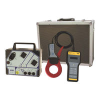
Insulation fault locator to locate insulation faults in ungrounded DC, AC and three-phase power supplies
Brand:
Bender
| Category:
Industrial Electrical
| Size: 21.79 MB
Table of Contents
Table of Contents
3
General Information
7
How to Use the Manual
7
Indication of Important Instructions and Information
7
Signs and Symbols
7
Service and Support
7
Training Courses and Seminars
8
Delivery Conditions
8
Inspection, Transport and Storage
8
Warranty and Liability
8
Disposal of Bender Devices
9
Safety
9
Function
10
Intended Use
10
Features
10
Areas of Application
10
Standards
10
System Variants
11
System Properties
11
Compatibility
12
Operating Principle of the EDS System
13
Schematic Diagram of an EDS System
15
Device Overview
16
External Dimensions of EDS44
16
View and Connections of EDS44
17
View and Connections of EDS44
18
Mounting
19
General Information
19
Installation Clearances
19
Screw Mounting
20
DIN Rail Mounting
21
Connection of the BB Bus
21
Connection to the Voltage Supply
22
Connection of the X1 Interface (I1, I2, A, B, M
22
Connection of the Relays
23
BS Bus Termination
23
Connection of the X2 Interface (K1-12/L1-12)
24
Connection of CTAC
24
Connection of Measuring Current Transformer CTBC
26
Connection of CTAF
27
Connection to a 3(N)AC System
28
Connection to an AC System
29
Connection to a DC System
30
Connection Example: ISOMETER® Iso685-D-P, EDS440-S, IOM441-S and EDS440-L
31
Display and Alarm Messages
32
Display Elements EDS44
32
Operating and Display Elements EDS44
32
Standard Display in Operating Mode
33
Standard Display EDS44
33
Alarm Messages
34
Insulation Fault (ALARM IΔL )
34
Residual Current Exceeded (ALARM I Δn )
35
Connection Fault of the Current Transformers
35
Device Error, BB Bus Error
36
Device Error, Failure BS Bus Master
37
Error Message
37
Acoustic Alarm Message
37
Commissioning
38
Requirements for Reliable Insulation Fault Location
38
Before Switching on
38
Switching on
39
Steps for Commissioning ISOMETER® and EDS
39
Periodic Verification
40
Device Communication
41
RS-485 Interface
41
Bender Sensor Bus (BS Bus)
41
Modbus RTU
42
Operation
43
Reading out and Setting the BS Address
43
Reading out a BS Address
43
Setting a BS Address
44
Extended Address Range (Offset = 80)
46
Display and Change of Transmission Protocols
47
Displaying the Current Transmission Protocol
47
Changing the Transmission Protocol
48
Resetting Saved Alarm Messages (RESET Button)
48
Deactivating the Buzzer (EDS44
48
Running a Test (TEST Button)
48
Settings
50
EDS Settings on the ISOMETER
50
Locating Current Injector Settings
50
Trigger Function
51
Fault Memory
51
Settings of Inputs and Outputs of the EDS44
51
Digital Inputs of the EDS44
51
Digital Outputs of the EDS44
52
Factory Settings
54
Alarm Messages
56
Diagrams
57
Response Sensitivity Curves
57
Characteristic Curves EDS440 for 3AC Systems
58
Characteristic Curves EDS440 for AC Systems
60
Characteristic Curve of EDS440 for Low Voltages in DC, AC and 3NAC Systems
61
Characteristic Curves EDS440 for DC Systems
62
Characteristic Curves EDS441 for AC Systems
65
Characteristic Curves EDS441 for DC Systems
66
Characteristic Curves of EDS441-LAB for AC Systems
68
Characteristic Curves EDS441-LAB for DC Systems
69
Response Values of EDS440-LAF for DC Systems
71
Response Values of EDS440-LAF for AC Systems
71
Fault Curve EDS440 and EDS441
72
Technical Data
73
Technical Data ISOSCAN® EDS440 and EDS441
73
Standards and Certifications
79
Ordering Data
80
Insulation Fault Locators
80
Accessories
80
Measuring Current Transformers
81
Change History
83
Advertisement
Bender EDS440 Manual (76 pages)
Brand:
Bender
| Category:
Measuring Instruments
| Size: 2.37 MB
Table of Contents
Table of Contents
3
Important Information
7
How to Use this Manual
7
Technical Support: Service and Support
8
First Level Support
8
Repair Service
8
Field Service
8
Training Courses
8
Delivery Conditions
9
Inspection, Transport and Storage
9
Warranty and Liability
9
Disposal
9
Overview of Chapters
10
Safety Instructions
11
General Safety Instructions
11
Intended Use
11
Device-Specific Safety Instructions
11
System Description
13
System Components
13
Overview of System Components
13
Insulation Fault Location Equipment Type List
14
Accessories
15
Function of the System Components
16
Locating Current Injector PGH18
16
Insulation Fault Locator EDS195PM
16
Measuring Clamps
16
Coupling Device AGE185
17
Operating Principle for Insulation Fault Location (IΔL)
17
Schematic Diagram EDS System
18
Test Cycle
18
Definitions
19
Currents in the EDS System
19
Operating Principle for Residual Current Measurement (Iδn)
20
Considerations Prior to Use
21
How Does the Equipment for Insulation Fault Location Work
21
Requirements for Reliable Insulation Fault Location
22
Reduced Locating Current
24
Response Sensitivity Characteristics of the EDS195PM
24
Response Characteristics for Main Circuits in 3AC Systems
26
Response Characteristics for Main Circuits in AC Systems
27
Response Characteristics for Main Circuits in DC Systems
27
Response Characteristics for Control Circuits in AC Systems
28
Response Characteristics for Control Circuits in DC Systems
28
Connecting the Locating Current Injector
29
Disconnecting Insulation Monitoring Device
29
Locating Current Injector in an Electrically Isolated IT System
29
Connection to a Live IT System
30
Connection to a PV System
31
Operation
33
Short Description of Insulation Fault Location (EDS Mode)
33
Commissioning the PGH18
33
Insulation Fault Location Using EDS195PM
33
Detailed Description of Insulation Fault Location
33
Description of a Residual Current Measurement
33
Displays and Controls on the PGH18
34
Displays and Controls on the EDS195PM
35
Operating the EDS195PM
36
Switching on and off the Device
36
Changing the Measuring Clamp
37
Improved Legibility Due to Display Lighting
37
Changing between Insulation Fault Location IΔL and Residual Current Measurement Iδn Operating Modes
37
Quickly Checking the Response Values for IΔL and Iδn
37
Checking Info Menu
37
Significance of the Display Elements
38
Standard Displays on the EDS195PM
39
EDS Measurement (IΔL)
39
Standard Display if There Is no Cable to be Measured in the Clamp
39
Standard Display for EDS Measurement (IΔL) with Cable in the Clamp
39
Standard Display for Measuring Faults or Pauses between Changes in Polarity of the Measuring Pulse
39
RCM Measurement (Iδn)
39
Standard Display for RCM Measurement (Iδn) with Cable in the Clamp
39
Alarms During EDS Measurement or RCM Measurement
40
Indication of Device and Measuring Errors
40
Factory Settings EDS195PM (State as Supplied)
41
Menu Structure
42
Navigating in the Menu
43
Menu Item: Settings
43
Menu Item: System
44
Menu Item: Harmonics
44
Menu Item: IΔL Alarms
44
Menu Item: Iδn Logger
45
Practical Usage
45
Insulation Fault Location in a System Without a Permanently Installed EDS System
45
Insulation Fault Location in a System with a Permanently Installed EDS System
48
Insulation Fault Location in Diode-Decoupled DC Systems
50
Usage of the EDS195PM as a Residual Current Meter
52
Indication of the Harmonics During Residual Current Measurement
53
Coupling Device AGE185 for Higher System Voltages
54
Power Supply for the EDS195PM
55
Displaying Charge State
55
Changing Batteries
55
Power Supply Unit Supplied
55
Technical Specifications
56
Technical Specifications for the System EDS309
56
Technical Specifications PGH18
56
Technical Specifications EDS195PM
57
Technical Specifications Measuring Clamps
58
Technical Specifications AGE185
59
Standards and Certifications
59
Dimension Diagrams
60
Status Word
61
Ordering Data Including Accessories
62
Component List
63
Frequently Asked Questions
64
Additional Fault Location Information Using the Eds309X
65
Required Equipment
65
Irdh575B2- 435
65
Collecting and Analysing Information
65
Taking Measurements
66
Index
71
Bender EDS440 Quick Start Manual (17 pages)
Insulating fault locator
Brand:
Bender
| Category:
Industrial Equipment
| Size: 1.24 MB
Table of Contents
Uso Apropiado
3
Montage
4
Montaje
5
Inbetriebnahme des Geräts
8
Commissioning of the Device
8
Mise en Service de L'appareil
9
Puesta en Marcha del Equipo
9
Bedienfeld und Bedienung
10
Operation
10
Technische Daten
14
Technical Data
14
Caractéristiques Techniques
15
Datos Técnicos
15
Advertisement
Bender EDS440 Connection Manual (16 pages)
Brand:
Bender
| Category:
Relays
| Size: 9.77 MB
Advertisement
Related Products
Bender EDS3090
Bender EDS3092
Bender EDS3096
Bender EDS150
Bender EDS309 Series
Bender EDS195PM
Bender EDS440-L
Bender EDS440-S
Bender EDS440-LAF-4
Bender EDS440-S-1
Bender Categories
Measuring Instruments
Monitor
Control Unit
Control Panel
Relays
More Bender Manuals
Login
Sign In
OR
Sign in with Facebook
Sign in with Google
Upload manual
Upload from disk
Upload from URL