Table of Contents
Advertisement
Quick Links
Handbuch/Manual
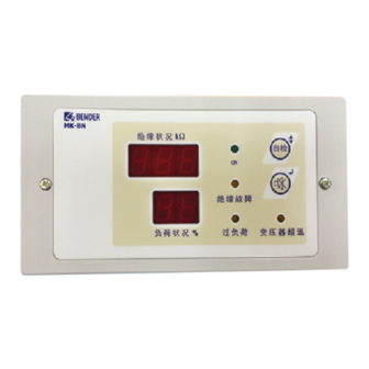
MK2007CBM(T)
Melde- und Prüfkombination für
medizinisch genutzte Bereiche
Bestimmungsgemäße Verwendung
Die Melde- und Prüfkombination MK2007CBM(T) dient zur Anzei-
ge von Betriebs- und Fehlermeldungen von Isolationsüberwa-
chungsgeräten 107TD47 und isoMED427P.
Normen
Die Melde-und Prüfkombination MK2007CBM(T) entspricht den
Gerätenormen und Errichtungsbestimmungen für elektrische
Anlagen in medizinisch genutzten Räumen:
IEC 60364-7-710:2002,
HD 60364-7-710: 2012-10,
DIN VDE 0100-710:2012-10; VDE 0100-710:2012-10
Sicherheitshinweise allgemein
Bestandteil der Gerätedokumentation sind neben diesem Daten-
blatt die beiliegenden „Wichtigen sicherheitstechnischen Hin-
weise für Bender-Produkte".
Funktionsbeschreibung
Anzeigen
MK2007CBM(T), Adress-Bereich 1...90 ab SW-Version 1.90, stellt
die von den Isolations-Überwachungsgeräten über den BMS-Bus
ausgegebene Alarmmeldungen und Messwerte auf den Sieben-
segment-Anzeigen und LEDs dar. Zusätzlich kann die Alarmmel-
dung eines weiteren Isolations-Überwachungsgerätes für OP-
Leuchten-Kreise angezeigt werden. Die Meldung „OP" erscheint
dann alternierend zum aktuellen Laststrom-Messwert auf dem
Display „TRANSFORMER LOAD %" / „I/%".
Die Siebensegment-Displays zeigen an:
Isolationswerte in kΩ
Verhältnis des momentanen Laststroms zum maximal
erlaubten sekundärseitigen Laststrom I in %.
Durch LEDs angezeigt werden:
Betriebsbereitschaft (grün)
Isolationsfehler (gelb)
Überstrom (gelb)
Übertemperatur (gelb)
Gerätefehler des MK2007CBM(T) und des Isolationsüber-
wachungsgerätes
Selbsttest
Mit Hilfe der Taste „TEST" kann ein Selbsttest des MK2007CBM(T)
und des zugehörigen Isolationsüberwachungsgerätes gestartet
werden. Einzelheiten finden Sie in der Dokumentation des Isola-
tionsüberwachungsgerätes.
Betätigen Sie die Taste „TEST" länger als eine Sekunde. Als Folge
werden alle Segmente und Dezimalpunkte der Anzeigen akti-
viert, zusätzlich leuchten alle LEDs. Nach Loslassen der „TEST"-
Taste, wird der Lampentest beendet. Das angeschlossene Isolati-
onsüberwachungsgerät bekommt gleichzeitig über den BMS-
Bus den Auftrag, einen eigenen Selbsttest durchzuführen. Die
Alarme werden auf den Displays und den LEDs der Meldekombi-
nation nach einigen Sekunden angezeigt. Zusätzlich ertönt der
interne Summer. Danach schaltet die Meldekombination wieder
MK2007CBM_D00218_01_M_DEEN/10.2015
Remote alarm indicator and
test combination for
medically used rooms
Intended use
The MK2007CBM(T) alarm indicator and test combination is used
to indicate operating and fault messages of insulation monitor-
ing devices 107TD47 and isoMED427P.
Standards
The MK2007CBM(T) alarm indicator and test combination com-
plies with the following device standards and regulations for
erection of electrical equipment in medical locations:
IEC 60364-7-710:2002,
HD 60364-7-710: 2012-10
DIN VDE 0100-710:2012-10; VDE 0100-710:2012-10
General safety information
In addition to this data sheet, the documentation includes the
supplementary sheet "Important safety instructions for Bender
products".
Function
Indications
The alarm and operating messages from the insulation monitor-
ing devices are duplicated by the MK2007CBM(T), address range
1...90, software version 1.90 or higher, and indicated on a seven-
segment display and by LEDs. In addition, an alarm message from
an additional insulation monitoring device for operating theatre
lamp circuits can be indicated. In this case, the indication "OP" ap-
pears alternately with the current load current measuring value
on the display "TRANSFORMER LOAD %" / "I/%".
The seven-segment display indicates:
The insulation resistance in kΩ
The ratio of the instantaneous load current to the maxi-
mum permissible secondary-load current I in %.
LEDs indicate:
Readiness for operation (green)
Insulation faults (yellow)
Overcurrent (yellow)
Overtemperature (yellow)
Device fault MK2007CBM(T) and insulation monitoring
device
Self test
By pressing the "TEST" button, a self test of the MK2007CBM(T)
and the associated insulation monitoring device can be carried
out. For details refer to the documentation of the insulation mon-
itoring device.
Press the "TEST" button for at least 1 second. All segments and
decimal points on the display will be activated, in addition all
LEDs light up. After releasing the "TEST" button, the lamp test is
completed. At the same time, the connected insulation monitor-
ing device is being requested via the BMS bus to carry out a self
test. After a few seconds, the alarm messages are indicated on the
displays and by the LEDs of the alarm indicator and test combina-
tion. In addition the internal buzzer sounds. Afterwards the alarm
indicator and test combination returns to normal operation
1
Advertisement
Table of Contents

Related Manuals for Bender MK2007CBM


Summary of Contents for Bender MK2007CBM
- Page 1 Self test Selbsttest By pressing the “TEST“ button, a self test of the MK2007CBM(T) Mit Hilfe der Taste „TEST“ kann ein Selbsttest des MK2007CBM(T) and the associated insulation monitoring device can be carried und des zugehörigen Isolationsüberwachungsgerätes gestartet out.
- Page 2 Summers nach einer einstellbaren Zeit gewählt werden. time. Parametrieren Setting Die Melde- und Prüfkombination MK2007CBM(T) verfügt über The MK2007CBM(T) alarm indicator and test combination pro- ein Menü zur Einstellung der eigenen Parameter. vides a menu for setting customer-specific parameters Anzeige- und Bedienelemente Operating and display elements...
- Page 3 Device fault (see Isometer data sheet) Keine Verbindung zum BMS-Bus Master (MK2007CBM(T) im blinkend/ ein/ blinkend/ blinkend/ blinkend/ Slave-Betrieb). / No connection to BMS bus Master (MK2007CBM(T) in slave flashing “Er“ flashing flashing flashing mode). Daten-Kollision auf dem BMS-Bus, z.B. durch doppelt verge-...
- Page 4 MK2007CBM(T) Parameter Einstellbereich/ Werkseinstellung Display Bedeutung Meaning Setting range Factory setting “R“ Ausstieg aus dem Menü Leaving the menu 1 … 90 (ab Software- Changing the BMS address of BMS-Adresse MK2007… ändern Version 1.60/ 1 / (Master) MK2007… SW version 1.60...
- Page 5 MK2007CBM(T) Maßbild Dimension diagram Mounting Montage The alarm indicator and test combination is suitable for screw Die Melde- und Prüfkombination eignet sich für Schraubmonta- mounting. Available options are: ge in den Varianten: Flush mounting Unterputzmontage Required accessories: Hierfür benötigen Sie die mitgelieferte Unterputzdose.
- Page 6 Der BMS-Bus ist eine RS485-Schnittstelle mit Bender-inter- BMS bus nem Protokoll. The BMS bus is an RS485 interface with internal Bender Verbinden Sie die Klemmen A und B des Gerätes mit dem protocol. BMS-Bus, wie im Anschlussplan dargestellt. Beachten Sie Connect the terminals A and B of the device to the BMS dabei den Beipackzettel „BMS-Bus“.
-
Page 7: Technische Daten
Führen Sie einen Funktionstest der Meldekombi- Check the function of the alarm indicator by start- nation durch. Starten Sie dazu den Selbsttest der ing the self test of the MK2007CBM(T). MK2007CBM(T). GEFAHR DANGER... - Page 8 All rights reserved. Reprinting and duplicating only with Genehmigung des Herausgebers. Änderungen vorbehalten! permission of the publisher. Subject to change! © © Bender GmbH & Co. KG Bender GmbH & Co. KG Fotos: Bender Archiv. Photos: Bender archives. Bender GmbH & Co. KG Postfach 1161 •...
Need help?
Do you have a question about the MK2007CBM and is the answer not in the manual?
Questions and answers