Table of Contents
Advertisement
Quick Links
Colorful Technology Website:
http://www.colorful.cn
Thanks for purchasing Colorful series motherboard. This series of motherboards provides excellent performance and quality
assurance.
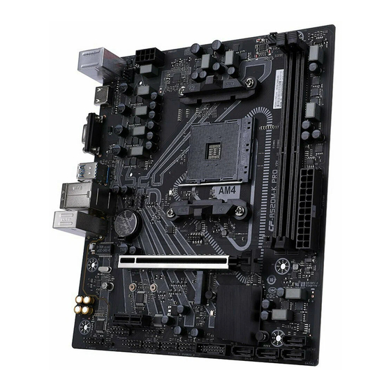
A520M-K PRO V14 motherboard based on AMD A520 chipset, support AMD AM4 socket, support dual channel DDR4
3200/3000/2933/2800/2666/2400/2133MHz memory, support PCI-E 3.0 standard.
The motherboard has 2*DDR4 memory slots,1*HDMI port, 1* VGA port, 4*SATA3.0 ports,6*USB3.1 Gen1 and 6*USB2.0 ports
(including headers),onboard 6-channel audio chipset,integrated 1000M LAN chipset !
The motherboard has 1*PCI Express3.0x16 slot,1*PCI Express3.0 x1 slot,1*M.2 slot,it had various extending schema and good
extensibility !
1.1.Packing Contents
1* Colorful A520M-K PRO V14 motherboard
2* SATA cables
1* Driver/Utility CD
1* User's Guide
1* I/O shield
1.2.MOTHERBOARD SPEC
·Supports Socket AM4
CPU
·Support 3rd Generation AMD Ryzen™ processors
Chipset
·AMD A520
·Offer 2 DIMM slots, support dual channel DDR4 memory
·the maximum supported capacity of a single memory slot
is 32GB, and the total memory capacity is 64GB
Main
·Support DDR4 3200/3000/2800/2666/2400/2133 MHz
Memory
·Warm tip: memory overclocking frequency also depends
on matching CPU and memory itself overclocking
performance!
·1*PCI Express 3.0 x16 slot
Slots
·1*PCI Express 3.0 x1 slot
·1*M.2 slot ( Support SATA and PCI-e 3.0 x4 SSD and 2242
/2260/2280 size)
·4*SATA3.0 port
Storage
·6*USB3.1 Gen1 and 6*USB2.0 ports(including headers)
USB
·1*PS/2 Mouse/ Keyboard port
·2*USB2.0 ports
·1*HDMI port
Rear IO
·1*VGA port
Connector
·4*USB3.1 GEN1 ports
·1*RJ45 LAN port(1000M)
·3*audio ports
A520M-K PRO V14
·1*Front panel audio connector ( F_AUDIO)
·1*System panel connector ( F_PANEL)
·2*USB2.0 headers ( FUSB20_1,FUSB20_2)
·1*USB3.1 GEN1 header ( FUSB30_1)
·1*CPU FAN headers ( CPU_FAN1)
·1*System FAN header ( SYS_FAN)
·1*PC speaker connector ( SPEAK)
Other
·1*Flash Bios header ( JBIOS)
Connectors
·1*12V 4Pin RGB FAN header ( FAN_RGB_HEADER)
·1*COM header ( COM_A)
·1*DEBUG header ( DEBUG)
·1*SPDIF header ( JSPDIF)
·1*Clear CMOS jumper ( CLR_CMOS)
·1*The power off charging jumper(JPS1),set whether the
USB ports can be charged in the power off state. Only the
PS2+USB ports on the back panel can support the
shutdown charging function.
High
·Onboard 6-channel High Definition audio chipset
Definition
·Support 3D surround sound
Audio
·Onboard 1000M LAN
Onboard
LAN
·Provides 10/100/1000Mb Ethernet
Advertisement
Table of Contents

Related Manuals for Colorful A520M-K PRO V14


Summary of Contents for Colorful A520M-K PRO V14
- Page 1 Thanks for purchasing Colorful series motherboard. This series of motherboards provides excellent performance and quality assurance. A520M-K PRO V14 motherboard based on AMD A520 chipset, support AMD AM4 socket, support dual channel DDR4 3200/3000/2933/2800/2666/2400/2133MHz memory, support PCI-E 3.0 standard. The motherboard has 2*DDR4 memory slots,1*HDMI port, 1* VGA port, 4*SATA3.0 ports,6*USB3.1 Gen1 and 6*USB2.0 ports (including headers),onboard 6-channel audio chipset,integrated 1000M LAN chipset !...
-
Page 2: Motherboard Layout
1.3.Motherboard Layout 1、 PS/2 Mouse/Keyboard and USB2.0 ports 2、 Connect to HDMI monitor 3、 Connect to VGA monitor 4、 Connect to USB3.1 GEN1 devices 5、 Connect to USB3.1 GEN1 devices and LAN 6、 Connect to audio devices 7、 Fan connector 8、... -
Page 3: Preparing The Motherboard
2.2.Preparing the Motherboard The motherboard shipped in the box does not contain a CPU or memory. You need to purchase a CPU, a CPU fan assembly, and memory to complete this installation. 2.2.1.Installing the CPU When installing a CPU, always remember to install a CPU heatsink. An CPU heatsink is necessary to prevent overheating and main- tain system stability. -
Page 4: Installing The Motherboard
2.4.Installing the Motherboard The sequence of installing the motherboard into the chassis depends on the chassis you are using and if you are replacing an existing motherboard or working with an empty chassis. Determine if it would be easier to make all the connections prior to this step or to secure the motherboard and then make all the connections. -
Page 5: Connecting Cables And Setting Switches
2.7.Connecting Cables and Setting Switches This section takes you through all the connections and switch settings necessary on the motherboard. This will include: Power Connections 24-pin ATX power 8-pin ATX 12V power Internal Headers Front panel USB Headers Audio Serial ATA III Chassis Fans Rear panel USB 2.0 Adapter Expansion slots... - Page 6 2.7.3.Serial ATA 3.0 6Gb/s connectors (7-pin) These connectors connect to Serial ATA 3.0 6Gb/s hard disk drives and optical drives via Serial ATA 3.0 6Gb/s signal cables. 2.7.4.USB2.0 connectors These connectors are for USB 2.0 ports. Connect the USB module cable to any of these connectors, then install the module to a slot opening at the back of the system chassis.
- Page 7 2.7.6.System panel connector This connector supports several chassis-mounted functions. Short circuit these two pins to power on Short circuit these two pins to restart 2.7.7.PCI Express3.0 x16 and PCI Express x1 slots The PCI Express x1 slots that are designed to accommodate less bandwidth-intensive cards, such as a modem or LAN card. The x1 slot provides 250 MB/sec bandwidth.
- Page 8 2.7.9.Clear CMOS Jumper: CLR_CMOS There is a CMOS RAM on board that has a power supply from external battery to keep the system configuration data. With the CMOS RAM, the system can automatically boot OS every time it is turned on. If you want to clear the system configuration, use the CLR_CMOS Jumper to clear data.
- Page 9 2.7.11.CPU, Chassis, and Power fan connectors Connect the fan cables to the fan connectors on the motherboard, making sure that the black wire of each cable matches the ground pin of the connector. 2.7.12.12V 4-pin RGB Fan/ LED header The motherboard offer two 12V 4-pin RGB LED Fan/Strip headers. During installation, the 12V pin on the RGB fan is aligned with the 12V pin on the motherboard.
-
Page 10: Bios Setup
2.7.14.Back Panel IO Connector <Backboard of A520M-K PRO V14> Parts PS/2 Mouse or Keyboard Connector This connector is for a PS/2 mouse or Keyboard. The standard RJ-45 jack is for connection to single Local Area Network (LAN). LAN Jack You can connect a network cable to it Lie-In(Blue) Used for external CD player, tape player or other audio devices. - Page 11 (Press the <F1> key to enter BIOS Setup,press the <F2> key to load default values and continue) If the boot self test (POST) program information is disappeared before you respond,you can turn it off and then turn on,or press the Reset button on the chassis to restart your computer, can also press < Ctrl > + < Alt > + < Delete > to restart the computer. BIOS Setup Program Function Keys <...
-
Page 12: Copyright Notice
4.Copyright Notice Copyright This motherboard manual belongs to Colorful Technology and Development CO, LTD. No one is permitted to copy, change, or translate without our written permission. Disclaimer The products name we mentioned in this manual is only for identifying, all of the brands belong to other company.
Need help?
Do you have a question about the A520M-K PRO V14 and is the answer not in the manual?
Questions and answers