Advertisement
Quick Links
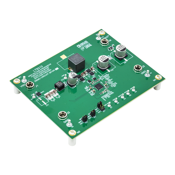
High Voltage, High Efficiency Synchronous Buck-Boost
DESCRIPTION
Demonstration circuit 2814A-A is a high voltage, high
efficiency synchronous buck-boost DC/DC converter with
an input voltage range of 8V to 80V. After the part has
started, the input voltage can run down to 3.5V. It can
supply a 3A maximum load current with an output range
of 8V to 16V. The demo board features the
controller. The constant frequency current mode architec-
ture allows a phase-lockable frequency of up to 400kHz,
while an optional input or output current feedback loop
provides support for applications such as battery charg-
ing. With a wide input range, wide output range, and
seamless transfers between operation modes, the LT8210
is ideal for industrial, automotive, medical, military, and
avionics applications.
The converter has four modes of operation: burst, pulse
skip, forced continuous mode, or pass-thru. Pass-thru is
a feature that passes the input directly to the output when
PERFORMANCE SUMMARY
PARAMETER
Input Voltage Range, V
Output Voltage, V
OUT
Maximum Output Current, I
Default Operating Frequency
Typical Efficiency
Arrow.com.
Downloaded from
Converter with Input to Output Pass-Thru
CONDITIONS
IN
V
= 3.5V (8V Start-Up) to 80V, I
IN
V
= 3.5V (8V Start-Up) to 80V, V
OUT
IN
6V
, 8V
IN
8V
, 8V
IN
12V
, 12V
IN
17V
, 16V
IN
30V
, 16V
IN
DEMO MANUAL DC2814A-A
the input voltage is within a user programmable window.
Switching losses drop to zero and efficiency is maximized.
For input voltage above or below the pass-thru window,
the buck or boost regulation loops maintain the output
at the set maximum or minimum values, respectively.
LT8210EUJ
Reverse input protection is also implemented on this
demo board.
The available versions of the DC2814A are:
DC2814A-A: 8V to 40V
Down to 3.5V
DC2814A-B: 9V to 36V
V
= 24V to 36V at 2.5A
OUT
DC2814A-C: 26V to 80V
Design files for this circuit board are
All registered trademarks and trademarks are the property of their respective owners.
Specifications are at T
= 25°C
A
= 0A to 3A
OUT
= 8V to 16V
OUT
(Boost), 3A
OUT
(Buck-Boost), 3A
OUT
(Pass-Thru), 3A
OUT
(Buck-Boost), 3A
OUT
(Buck), 3A
OUT
, 80V
Surge (60s), Operates
IN
IN
after Start-Up, V
= 8V to 16V at 3A
IN
OUT
, 80V
Surge (60s),
IN
IN
, V
= 36V to 56V at 2A
IN
OUT
available.
VALUE
8V to 40V Continuous, 80V Surge (60 Seconds)
(Operates Down to 3.5V after Start-Up)
8V to 16V
3A
385kHz (R
= 16.9k)
T
94%
94%
98%
95%
94%
LT8210
Rev. 0
1
Advertisement

Related Manuals for Linear Technology Analog Devices DC2814A-A


Summary of Contents for Linear Technology Analog Devices DC2814A-A
- Page 1 DEMO MANUAL DC2814A-A LT8210 High Voltage, High Efficiency Synchronous Buck-Boost Converter with Input to Output Pass-Thru DESCRIPTION Demonstration circuit 2814A-A is a high voltage, high the input voltage is within a user programmable window. efficiency synchronous buck-boost DC/DC converter with Switching losses drop to zero and efficiency is maximized.
-
Page 2: Quick Start Procedure
DEMO MANUAL DC2814A-A QUICK START PROCEDURE Demonstration circuit 2814A-A is easy to set up to the output voltage regulation, ripple voltage and evaluate the performance of the LT8210. Refer to the other parameters. following procedure: 6. After the part starts, the input voltage can be reduced 1. -
Page 3: Test Results
DEMO MANUAL DC2814A-A TEST RESULTS 20V/DIV 20V/DIV 5V/DIV 20V/DIV 50V/DIV 50V/DIV 50V/DIV 50V/DIV DC2814aa F05 DC2814aa F06 20ms/DIV 200ms/DIV Figure 5. ISO16750 4.6.4, Test A without Centralized Figure 6. LV124 E-04, Jumpstart (I = 3A) Load Dump Suppression (I = 3A) 5V/DIV 2V/DIV 20V/DIV... - Page 4 DEMO MANUAL DC2814A-A TEST RESULTS Figure 9. DC2814A-A Thermal Performance at 6V (Boost), 8V , 3A Load Current 50mV/DIV 50mV/DIV 5V/DIV 5V/DIV DC2814aa F10 DC2814aa F11 2ms/DIV 2µs/DIV Figure 10. DC2814A-A Load Transients at 6V (Boost), Figure 11. DC2814A-A Output Voltage Ripple at 6V (Boost), , 0.3A to 2.7A Load Current , 3A Load Current...
- Page 5 DEMO MANUAL DC2814A-A TEST RESULTS Figure 12. DC2814A-A Thermal Performance at 8V (Buck-Boost), 8V , 3A Load Current 50mV/DIV 50mV/DIV 5V/DIV 5V/DIV DC2814aa F13 2ms/DIV DC2814aa F14 2µs/DIV Figure 13. DC2814A-A Load Transients at 7.5V (Buck-Boost), Figure 14. DC2814A-A Output Voltage Ripple at 8V (Buck-Boost), 8V , 3A Load Current , 0.3A to 2.7A Load Current...
- Page 6 DEMO MANUAL DC2814A-A TEST RESULTS Figure 15. DC2814A-A Thermal Performance at 12V (Pass-Thru), 12V , 3A Load Current 200mV/DIV 5V/DIV 50mV/DIV 5V/DIV DC2814aa F16 DC2814aa F17 2ms/DIV 2µs/DIV Figure 17. DC2814A-A Output Voltage Ripple at 12V Figure 16. DC2814A-A Load Transients at 12V (Pass-Thru), (Pass-Thru), 12V , 3A Load Current...
- Page 7 DEMO MANUAL DC2814A-A TEST RESULTS Figure 18. DC2814A-A Thermal Performance at 17V (Buck-Boost), 16V , 3A Load Current 100mV/DIV 50mV/DIV 10V/DIV 10V/DIV DC2814aa F19 DC2814aa F20 2ms/DIV 2µs/DIV Figure 19. DC2814A-A Load Transients at 17V Figure 20. DC2814A-A Output Voltage Ripple at 17V (Buck-Boost), 16V , 0.3A to 2.7A Load Current (Buck-Boost), 16V...
- Page 8 DEMO MANUAL DC2814A-A TEST RESULTS Figure 21. DC2814A-A Thermal Performance at 30V (Buck), 16V , 3A Load Current 100mV/DIV 50mV/DIV 10V/DIV 10V/DIV DC2814aa F22 DC2814aa F23 2ms/DIV 2µs/DIV Figure 22. DC2814A-A Load Transients at 30V (Buck), Figure 23. DC2814A-A Output Voltage Ripple at 30V , 0.3A to 2.7A Load Current (Buck), 16V , 3A Load Current...
-
Page 9: Parts List
DEMO MANUAL DC2814A-A PARTS LIST ITEM QTY REFERENCE PART DESCRIPTION MANUFACTURER/PART NUMBER Required Circuit Components C1, CFOUT1 CAP , 1µF ,X7S, 100V, 10%, 0805, SOFT TERM MURATA GRJ21BC72A105KE11L TDK C2012X7S2A105K125AE C7, C8, C11, C12, C23 CAP , 0.1µF, X7S, 100V, 10%, 0603 TAIYO YUDEN HMK107C7104KA-T TDK C1608X7S2A104K080AB C9, C10, C21, C22,... - Page 10 DEMO MANUAL DC2814A-A PARTS LIST ITEM QTY REFERENCE PART DESCRIPTION MANUFACTURER/PART NUMBER MP1, MP2, MP3, MP4 STANDOFF , NYLON, SNAP-ON, 0.50" KEYSTONE 8833 PCB1 PCB, DC2814A PHASE 3 600-DC2814A R1A1 RES, 69.8kΩ, 1%, 1/16W, 0402 VISHAY CRCW040269K8FKED R1B1, R2B1 RES, 10kΩ, 1%, 1/16W, 0402, AEC-Q200 VISHAY CRCW040210K0FKED NIC NRC04F1002TRF R1C1, R2C1, R12,...
-
Page 11: Schematic Diagram
DEMO MANUAL DC2814A-A SCHEMATIC DIAGRAM Rev. 0 Information furnished by Analog Devices is believed to be accurate and reliable. However, no responsibility is assumed by Analog Devices for its use, nor for any infringements of patents or other rights of third parties that may result from its use. Specifications subject to change without notice. - Page 12 DEMO MANUAL DC2814A-A ESD Caution ESD (electrostatic discharge) sensitive device. Charged devices and circuit boards can discharge without detection. Although this product features patented or proprietary protection circuitry, damage may occur on devices subjected to high energy ESD. Therefore, proper ESD precautions should be taken to avoid performance degradation or loss of functionality. Legal Terms and Conditions By using the evaluation board discussed herein (together with any tools, components documentation or support materials, the “Evaluation Board”), you are agreeing to be bound by the terms and conditions set forth below (“Agreement”) unless you have purchased the Evaluation Board, in which case the Analog Devices Standard Terms and Conditions of Sale shall govern.
Need help?
Do you have a question about the Analog Devices DC2814A-A and is the answer not in the manual?
Questions and answers