Table of Contents
Advertisement
Quick Links
Description
Demonstration circuit 2197A features the
Quad 12-/10-/8-Bit PWM to VOUT DACs with 10ppm/°C
reference in a tiny 4.9mm × 4mm 16-lead MSOP package.
DC2197A-A is populated with the 2.5V, 12-bit version of
the LTC2645.
The LTC2645 measures the period and pulse width of the
Pulse Width Modulation (PWM) input and updates the volt-
age output DAC at each rising edge. The PWM frequency
can be any frequency between 30Hz and 100kHz. The input
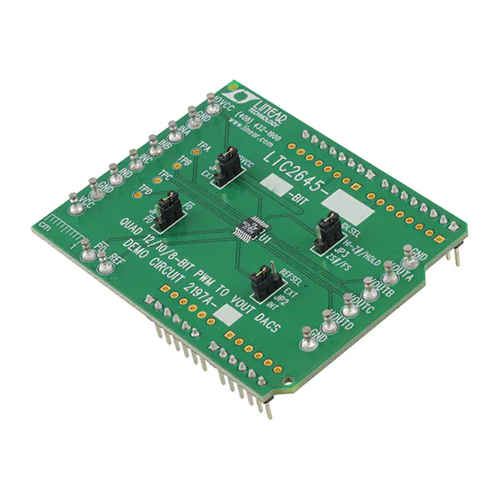
BoarD photo
OPTIONAL LOGIC
SUPPLY CONNECTION
1.71V TO 5.5V (SEE TEXT)
PWM
INPUTS
IOVCC
0
VCC CONNECTION
2.7V TO 5.5V (SEE TEXT)
DEMO MANUAL DC2197A
with 10ppm/°C Reference
LTC
2645,
level can be between 1.71V and 5.5V, set by a separate
®
IOVCC pin. This device solves many of the problems as-
sociated with filtering a PWM signal to produce an analog
voltage, producing a fast-settling, accurate analog voltage
in response to a digital PWM input.
Design files for this circuit board are available at
http://www.linear.com/demo
L, LT, LTC, LTM, Linear Technology and the Linear logo are registered trademarks of Linear
Technology Corporation. All other trademarks are the property of their respective owners.
POWER-DOWN, REFERENCE
CONNECTIONS (SEE TEXT)
Figure 1. Basic Connections
Quad 12-/10-/8-Bit
PWM to VOUT DACs
HEADERS ON REVERSE SIDE ARE FOR
OPERATION WITH A LINDUINO BOARD.
(SEE TEXT)
ANALOG
OUTPUTS
dc2197afa
1
Advertisement
Table of Contents

Related Manuals for Linear Technology DC2197A


Summary of Contents for Linear Technology DC2197A
- Page 1 DAC at each rising edge. The PWM frequency L, LT, LTC, LTM, Linear Technology and the Linear logo are registered trademarks of Linear can be any frequency between 30Hz and 100kHz. The input Technology Corporation. All other trademarks are the property of their respective owners.
- Page 2 (PLC), optocoupler, etc. , C#, etc.) The program can be modified as desired to change or add functionality. Install the DC2197A onto the DC2026 as shown in Figure 2. Ensure that the IOVCC jumper is set to VCC. dc2197afa...
- Page 3 DEMO MANUAL DC2197A Quick start proceDure LINE UP AND INSERT CONNECTORS ANALOG OUTPUTS CONNECTION TO COMPUTER Figure 2. Linduino Connections Follow the procedure for installing drivers and sketchbook in the DC2026 Demo Manual. Upload the DC2197 program (“sketch”). Select: File → Sketchbook → Part Number → 2000 → 2600 →2645 → DC2197 Then click the “Upload”...
- Page 4 Arduino shield port that is compatible with the A Quartus archive project and FPGA configuration bi- DC2197A. The C5G provides 5V to the LTC2645’s VCC nary file are included with the DC2197A design files. supply, so IOVCC must be changed to 3.3V to match The program sends PWM signals to all four DACs.
- Page 5 DEMO MANUAL DC2197A Quick start proceDure Figure 4. Altera Program Operation Figure 5. PWM Details dc2197afa...
- Page 6 DEMO MANUAL DC2197A Quick start proceDure EXTERNAL CONNECTIONS Arduino Shield Connections (IOL1, IOH1, AD0, POWER headers installed on back side of board) – These headers GND: Four ground turrets are provided. These are con- mate with the DC2026 Linduino and other Arduino Uno nected directly to the ground plane and are the common compatible microcontroller boards.
- Page 7 Information furnished by Linear Technology Corporation is believed to be accurate and reliable. However, no responsibility is assumed for its use. Linear Technology Corporation makes no representa- tion that the interconnection of its circuits as described herein will not infringe on existing patent rights.
- Page 8 Linear Technology Corporation (LTC) provides the enclosed product(s) under the following AS IS conditions: This demonstration board (DEMO BOARD) kit being sold or provided by Linear Technology is intended for use for ENGINEERING DEVELOPMENT OR EVALUATION PURPOSES ONLY and is not provided by LTC for commercial use. As such, the DEMO BOARD herein may not be complete in terms of required design-, marketing-, and/or manufacturing-related protective considerations, including but not limited to product safety measures typically found in finished commercial goods.
Need help?
Do you have a question about the DC2197A and is the answer not in the manual?
Questions and answers