Advertisement
Description
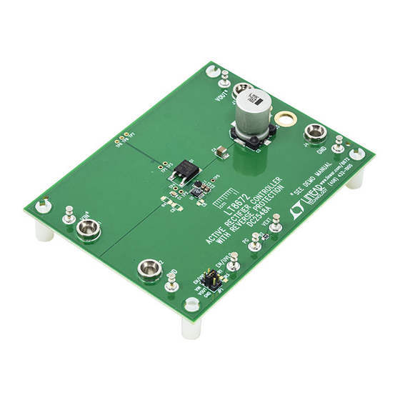
Demonstration circuit 2548A is an active rectifier with
reverse protection featuring the
board is designed for 5A load current. The input volt-
age range of the LT8672 is –40V to +42V. Two clamping
diodes, D1 and D2, are used on the board to protect the
IC from overvoltage spikes at the input, thus limiting the
application's DC input voltage range to –15V and +35V.
The voltage drop on the MOSFET is 20mV in regulation.
The LT8672 can rectify input ripple with an amplitude of
6V
and a frequency of up to 50kHz, or with an ampli-
P-P
tude of 2V
and a frequency of up to 100kHz. High fre-
P-P
quency ripple should not be applied at full load current
for more than a few minutes, otherwise C5 may overheat.
JP1 can be used to set the LT8672 in shutdown mode.
It can be turned on by connecting the EN/UVLO to V
V
. A digital signal can also be applied at the EN/UVLO
OUT
turret to control the part. Due to the presence of the exter-
nal MOSFET's body diode, the load is not disconnected
from the input if the part is shut down.
SYMBOL
PARAMETER
V
DC Operating Input Voltage Range
IN
f (AC)
Maximum Frequency of AC Input Signal to
Be Rectified
I
Max Output Current
OUT
Arrow.com.
Downloaded from
The PG pin on the demo board can be easily by applying
LT
8672. The demo
a voltage source between VEXT and GND. VEXT must not
®
exceed 5V.
The demo board allows installation of an EMI filter at the
output. To use the EMI filter, install L2, C7, and remove
C5 on the board. In addition, multiple MOSFET footprints
are provided on the backside of the board, making it con-
venient to use other MOSFETs.
The LT8672 data sheet gives a complete description of
the part, operation and application information. The data
sheet must be read in conjunction with this demo manual
for demo circuit 2548A. The LT8672 is assembled in a
10-lead MSOP package. Proper board layout is essential
for maximum thermal and electrical performance. See the
or
data sheet sections for details.
IN
Design files for this circuit board are available at
http://www.linear.com/demo/DC2548A
L, LT, LTC, LTM, Linear Technology and the Linear logo are registered trademarks of Analog
Devices, Inc. All other trademarks are the property of their respective owners.
Specifications are at T
CONDITIONS
V
< 6V, C
P-P
GATE-SOURCE
V
< 2V, C
P-P
GATE-SOURCE
V
=12V
IN
DEMO MANUAL DC2548A
Active Rectifier Controller
with Reverse Protection
= 25°C
A
MIN
–15
= 10nF
50
= 10nF
100
LT8672
TYP
MAX
UNITS
35
kHz
kHz
5
dc2548af
1
V
A
Advertisement
Table of Contents

Related Manuals for Linear Technology DC2548A


Summary of Contents for Linear Technology DC2548A
- Page 1 MOSFET’s body diode, the load is not disconnected L, LT, LTC, LTM, Linear Technology and the Linear logo are registered trademarks of Analog from the input if the part is shut down. Devices, Inc. All other trademarks are the property of their respective owners.
- Page 2 DEMO MANUAL DC2548A performance summary 1V/DIV BATT 1V/DIV DC2548 F01 10µs/DIV Figure 1. Rectification of Input Ripple (f = 30kHz, Load = 5A) dc2548af Arrow.com. Arrow.com. Downloaded from Downloaded from...
- Page 3 DEMO MANUAL DC2548A Quick start proceDure Demonstration circuit 2548A is easy to set up to evalu- NOTE. If there is no output, temporarily disconnect the ate the performance of the LT8672. Refer to Figure 2 for load to make sure that the load is not shorted.
- Page 4 DEMO MANUAL DC2548A parts List ITEM REFERENCE PART DESCRIPTION MANUFACTURER/PART NUMBER Required Circuit Components CAP ., CER., 0.01µF, X7R, 50V, 10%, 0805 MURATA, GRM216R71H103KA01D C2, C3 CAP ., CER., 1µF, X7R, 50V, 10%, 0805 MURATA, GRM21BR71H105KA12L CAP ., CER., 4.7µF, X7R, 50V, 10%, 1210 MURATA, GRM32ER71H475KA88L CAP ., ALUM., 470µF, 35V, 20%...
- Page 5 Information furnished by Linear Technology Corporation is believed to be accurate and reliable. However, no responsibility is assumed for its use. Linear Technology Corporation makes no representa- tion that the interconnection of its circuits as described herein will not infringe on existing patent rights.
- Page 6 Linear Technology Corporation (LTC) provides the enclosed product(s) under the following AS IS conditions: This demonstration board (DEMO BOARD) kit being sold or provided by Linear Technology is intended for use for ENGINEERING DEVELOPMENT OR EVALUATION PURPOSES ONLY and is not provided by LTC for commercial use. As such, the DEMO BOARD herein may not be complete in terms of required design-, marketing-, and/or manufacturing-related protective considerations, including but not limited to product safety measures typically found in finished commercial goods.
Need help?
Do you have a question about the DC2548A and is the answer not in the manual?
Questions and answers