Advertisement
Quick Links
Oversampling ADCs with Configurable Digital Filter
Description
Demonstration circuit 2222A features the
and
LTC2512-24
ADCs. The LTC2508-32 and LTC2512-24
are low power, low noise, high speed, 32-bit/24-bit SAR
ADCs with an integrated configurable digital averaging
filter that operate from a single 2.5V supply. The following
text refers to the LTC2508-32 but applies to both parts,
the only difference being sample rate and number of bits.
The DC2222A demonstrates the DC and AC performance
of the LTC2508-32 in conjunction with the DC590 or
DC2026 QuikEval™ and DC890 PScope™ data collection
boards. Use the DC590 or DC2026 to demonstrate DC
performance such as peak-to-peak noise and DC linearity.
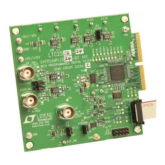
–9V
GND
9V
0V TO V
REF
0V TO V
REF
100MHz
MAX
2.5V
P-P
DEMO MANUAL DC2222A
LTC2508-32/LTC2512-24: 32-Bit/24-Bit
LTC
2508-32
Use the DC890 if precise sampling rates are required or to
®
demonstrate AC performance such as SNR, THD, SINAD
and SFDR. The DC2222A is intended to show recommended
grounding, component placement and selection, routing
and bypassing for this ADC.
Design files for this circuit board including the
schematic, BOM and layout are available at
http://www.linear.com/demo/DC2222A
code on the back of the board.
L, LT, LTC, LTM, Linear Technology and the Linear logo are registered trademarks and
QuikEval and PScope are trademarks of Linear Technology Corporation. All other trademarks are
the property of their respective owners.
Figure 1. DC2222A Connection Diagram
or scan the QR
TO
DC890
TO
DC590 OR
DC2026
dc2222af
1
Advertisement

Related Manuals for Linear Technology DC2222A


Summary of Contents for Linear Technology DC2222A
- Page 1 DC2026 QuikEval™ and DC890 PScope™ data collection L, LT, LTC, LTM, Linear Technology and the Linear logo are registered trademarks and boards. Use the DC590 or DC2026 to demonstrate DC QuikEval and PScope are trademarks of Linear Technology Corporation. All other trademarks are performance such as peak-to-peak noise and DC linearity.
-
Page 2: Quick Start Procedure
VCCIO (JP3) is set to the 2.5V position. Controlling read the filtered output with Verify and Distributed Read the DC2222A with the DC890 while JP3 of the DC2222A not selected and the Down Sampling Factor (DF) set to is in the 3.3V position will cause noticeable performance the smallest possible value. - Page 3 DEMO MANUAL DC2222A Quick start proceDure Figure 2. PScope Toolbar Figure 3a. LTC2508 Configuration Options Menu Figure 3b. LTC2512 Configuration Options Menu dc2222af...
- Page 4 Apply a signal source to J4 and J2. No clock signal is necessary at J1 when using a QuikEval con- VCCIO (JP3) of the DC2222A should be in the 3.3V posi- troller. The clock signal is provided through the QuikEval tion for DC590 or DC2026 (QuikEval) operation.
- Page 5 DEMO MANUAL DC2222A Dc590 or Dc2026 Quick start proceDure loaded automatically. Click the Collect button (See Figure 5) Increasing DF will reduce the noise as shown in the histo- to begin reading the ADC. gram of Figure 6. The noise will be reduced by the square...
- Page 6 The default driver for the analog inputs of the ADC on the edges may compromise the SNR of the converter in the DC2222A is shown in Figures 8a and 8b. These circuits presence of high amplitude higher frequency input signals.
-
Page 7: Data Collection
1206 5040 200Hz. The input signal level is approximately –1dBFS. The input is level shifted and filtered with the circuit shown in Figure 9. A typical FFT obtained with DC2222A is shown – 4.7µF 4.7µF TO A in Figure 4. - Page 8 The area immediately surrounding the ADC on to further reduce distortion NPO or silver mica capaci- the DC2222A should be used as a guideline for placement, tors should be used. Any buffer used for AC applications and routing of the various components associated with the should have low distortion, low noise and a fast settling ADC.
- Page 9 Information furnished by Linear Technology Corporation is believed to be accurate and reliable. However, no responsibility is assumed for its use. Linear Technology Corporation makes no representa- tion that the interconnection of its circuits as described herein will not infringe on existing patent rights.
- Page 10 Linear Technology Corporation (LTC) provides the enclosed product(s) under the following AS IS conditions: This demonstration board (DEMO BOARD) kit being sold or provided by Linear Technology is intended for use for ENGINEERING DEVELOPMENT OR EVALUATION PURPOSES ONLY and is not provided by LTC for commercial use. As such, the DEMO BOARD herein may not be complete in terms of required design-, marketing-, and/or manufacturing-related protective considerations, including but not limited to product safety measures typically found in finished commercial goods.
Need help?
Do you have a question about the DC2222A and is the answer not in the manual?
Questions and answers