Advertisement
Quick Links
Surround / Front:
Leave this manual with party responsible for use
and operation.
CAUTION! Risk of Cuts, Abrasions or Flying Debris.
Wear protective gloves and safety glasses during instal-
lation. Sheet metal edges are sharp.
DANGER
DO NOT TOUCH GLASS
NEVER ALLOW CHILDREN
A barrier designed to reduce the risk of
burns from the hot viewing glass is provided
with this appliance and shall be installed for
the protection of children and other at-risk
individuals.
• CAREFULLY SUPERVISE children in same room as
fireplace.
• Alert children and adults to hazards of high temperatures.
High temperatures may ignite clothing or other
flammable materials.
• Keep clothing, furniture, draperies and other flammable
materials away.
• Do NOT operate with protective barriers open or removed.
• The decorative front must remain closed if children will be
present during the operation of the fireplace.
• The decorative front may be made operable per these
instructions. This may be done only upon request of
a person responsible for the use and operation of the
fireplace.
• The decorative front can be returned to the locked position
following these instructions.
INTRODUCTION
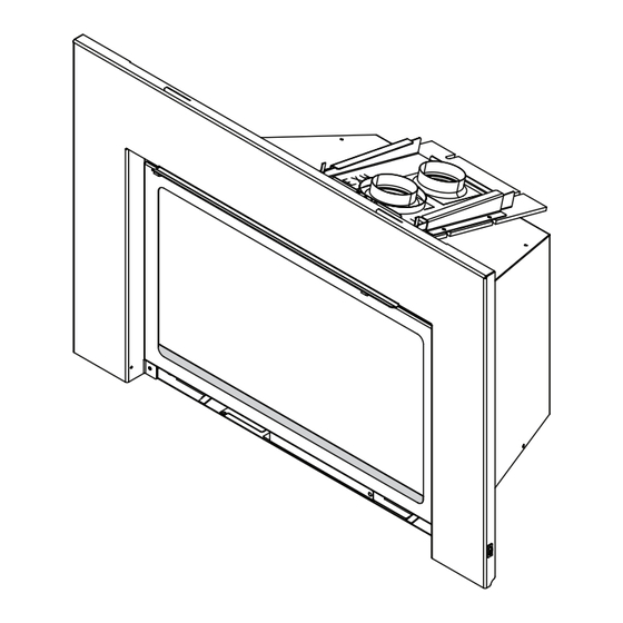
The surround is used to fill the space between the insert
and the solid fuel firebox opening. The front is placed onto
the surround after it is attached to the insert. The surround
is required.
WARNING! Risk of Fire! Combustible materials MUST
NOT overlap or be placed under a surround.
Hearth & Home Technologies • Insert Surround / Front Installation Instructions • 2532-921 Rev. G • 3/22
TA-EXC25/30/35, INFIT-25/30/35 IA-MI25/30/35, FS-MI25/30/35, MFV-EXC25/30/35,
FA-EXC25/30/35, HARC-MI25/30/35, CSFI25/30/35, CASFI25/30/35
Installation Instructions -
HOT GLASS WILL
CAUSE BURNS.
UNTIL COOLED.
TO TOUCH GLASS.
Combustible Materials Specification
Materials made of or surfaced with wood, compressed
paper, plant fibers, plastics, or other material that can ig-
nite and burn, whether flame proofed or not, or plastered
or unplastered shall be considered combustible materials.
SURROUND & FRONT INSTALLATION
1. Remove the shipping bracket from the surround. See
Figure 2.
2. Locate the coiled rocker switch wires on the insert. The
wire assembly is zip-tied to the right side of the appliance
outer wrap.
3. Run the low voltage rocker switch wires behind the
surround. Connect the low voltage wires to the rocker
switch. See Figure 1.
Note: For alternative rocker switch location using the rocker
switch mounting bracket see Figure 2 for PROVIDENT/
JASPER metal inserts and see Figure 3 for all other
metal inserts.
4. Attach surround to the insert with four screws
(located in appliance manual bag). See Figure 4. When
installing a 4-sided surround, install shoulder screws
in bottom corners of surround opening. Bend tabs on
vanity panel toward the 90° return bend and hang on
shoulder screws. See Figures 5 and 6.
ROCKER
SWITCH
SURROUND
Figure 1 Rocker Switch Detail
APPLIANCE
1
Advertisement

Related Manuals for Hearth & Home TA-EXC25


Summary of Contents for Hearth & Home TA-EXC25
- Page 1 Surround / Front: TA-EXC25/30/35, INFIT-25/30/35 IA-MI25/30/35, FS-MI25/30/35, MFV-EXC25/30/35, FA-EXC25/30/35, HARC-MI25/30/35, CSFI25/30/35, CASFI25/30/35 Installation Instructions - Combustible Materials Specification Leave this manual with party responsible for use Materials made of or surfaced with wood, compressed and operation. paper, plant fibers, plastics, or other material that can ig- nite and burn, whether flame proofed or not, or plastered CAUTION! Risk of Cuts, Abrasions or Flying Debris.
- Page 2 SHOULDER SCREW HAND BEND Figure 2 PROVIDENT/JASPER Bracket Location Figure 5 Hand Bend Tab & Shoulder Screw SHOULDER SCREWS BRACKET SLOT SWITCH Figure 3 Rocker Switch in Mounting Bracket Figure 6 Vanity Panel Installed Note: When being used with 4-sided surround, bend bracket approximately 15°at the hand bend line to avoid contact with vanity panel.
- Page 3 8. See below chart for glass vanity install details. FRONT REFERENCE FIGURE FA-EXC25/30/35 TA-EXC25/30/35 To install glass vanity, tuck it between the glass and glass frame as shown in Figure 11. Figure 8 Install Front 6. Slide the hood forward until it bottoms out on the front/mesh.
- Page 4 MI30-5040CS-BK ROCKER SWITCH 2532-299 MOUNTING BRACKET (OPTIONAL, SEE FIGURE 2) MI35-5040CS-BK VANITY PANEL 2532-204 CUST-SRND-MI FRONTS DESCRIPTION PART NUMBER TA-EXC25-(All colors) 2531-034 MESH TA-EXC30-(All colors) 2532-034 TA-EXC35-(All colors) 2533-034 TA-EXC25-(All colors) 2531-247 TA-EXC30-(All colors) GLASS VANITY PANEL 2532-247 TA-EXC35-(All colors)
- Page 5 FRONTS (continued) DESCRIPTION PART NUMBER FS-MI25-(All colors) 2531-034 FS-MI30-(All colors) MESH 2532-034 FS-MI35-(All colors) 2533-034 FA-EXC25-BK 2531-034 MESH FA-EXC30-BK 2532-034 FA-EXC35-BK 2533-034 FA-EXC25-BK 2531-247 FA-EXC30-BK GLASS VANITY PANEL 2532-247 FA-EXC35-BK 2533-247 CSFI25(All colors) 2531-034 CSFI30(All colors) MESH 2532-034 CSFI35(All colors) 2533-034 CASFI25(All colors) 2531-034...
Need help?
Do you have a question about the TA-EXC25 and is the answer not in the manual?
Questions and answers