
Related Manuals for DANIEL 700


Summary of Contents for DANIEL 700
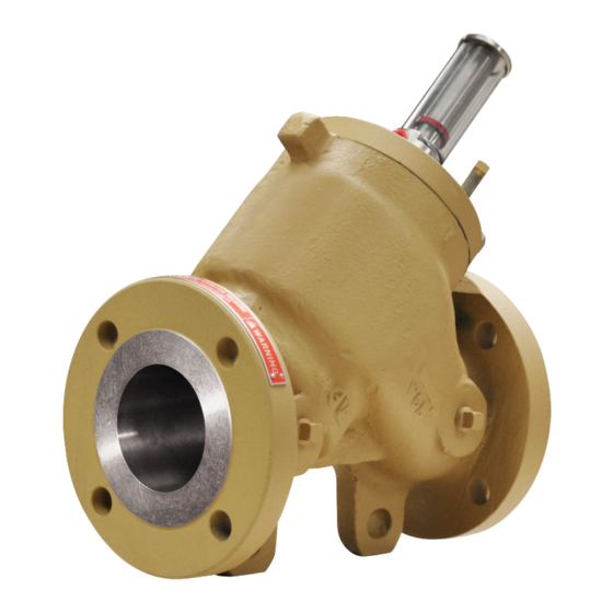
- Page 1 DANIEL ® CONTROL VALVES USER MANUAL MODEL 700 NPS 2 THROUGH 16 / CLASS 150-600 Decades Proven. Field Chosen. ™ NOVEMBER 2020...
-
Page 2: Table Of Contents
1.2 Hazard messages......................... 7 1.3 Personnel qualifications....................... 7 1.4 Warranty restrictions........................9 1.5 Assistance............................9 1.6 Description of the Model 700 Control Valves................9 1.7 Agency certifications for control valves Model 700..............18 Chapter 2 Operating conditions and specifications..............19 2.1 Operating conditions for the control valve................. 19 2.2 Specifications for the control valve.................... - Page 3 10.2 Verify the return to operational condition................64 Chapter 11 Spare parts.......................65 11.1 Order spare parts........................65 Chapter 12 Decommission......................67 12.1 Shut down the control valve....................67 12.2 Shipment of the control valve....................67 Daniel Series 700 Control Valve www.Daniel.com...
-
Page 4: Part I Plan
MODEL 700 CONTROL VALVE User manual Plan P/N 3-9008-553 November 2020 Part I Plan User manual www.Daniel.com... -
Page 5: Chapter 1 Introduction
Personnel qualifications Read and follow all instructions, dangers, warnings, and cautions to avoid personal injury or property damage during system operation. Daniel is not responsible for damage or injury resulting from unsafe use of products, lack of maintenance, incorrect installation of equipment or system operation. - Page 6 Failure to comply may result in personnel injury. WARNING RISK TO PERSONNEL AND EQUIPMENT Failure to follow the installation, operation or maintenance instructions for a Daniel product could lead to serious injury or death from explosion or exposure to dangerous substances. To reduce the risk: •...
-
Page 7: Warranty Restrictions
Daniel assumes no responsibility for incidents, or consequences of incidents, occurring as a result of the use of this product by others than Daniel or its designated personnel, and have no liability whatsoever for any such work. - Page 8 Control valve applications This is the starting point for unlimited control applications. The basic valve needs to incorporate a pilot control loop, which is mandatory for it to function, see Daniel Liquid Control Valves Technical Guide (P/N DAN-LIQ-TG-44) for specific applications.
- Page 9 (P1 minus P2) is slightly greater than the force applied by the main valve spring. In a non-control state, the main valve is opened in a percentage directly proportional to (P1 minus P2). User manual www.Daniel.com...
- Page 10 The pilot control is a variable orifice that regulates the pressure at Y-port (P3) by controlling the flow through Z-port. Increasing or decreasing the Y-port pressure (P3) causes the piston to change positions. Daniel Series 700 Control Valve www.Daniel.com...
- Page 11 USER MANUAL User manual Introduction P/N 3-9008-553 November 2020 Figure 1-3: Pilot in partially open position A. Needle valve / strainer B. Manual pilot control C. Inlet pressure D. Outlet pressure E. Controlled pressure User manual www.Daniel.com...
- Page 12 Parts list for the Series 700 Control Valves Figure 1-4: Part identification for an NPS 2-12 inch Control Valve NOTICE Item numbers are not meant to be consecutively numbered. Table 1-1: Part description for Model 700 Control Valve NPS 2 - 12 Item number Description Quantity...
- Page 13 USER MANUAL User manual Introduction P/N 3-9008-553 November 2020 Table 1-1: Part description for Model 700 Control Valve NPS 2 - 12 (continued) Item number Description Quantity Retaining ring Spring O-ring Cylinder head Screw Jack-out screws Indicator stem visual Indicator stem micro-switch...
- Page 14 MODEL 700 CONTROL VALVE Introduction User manual November 2020 P/N 3-9008-553 Table 1-1: Part description for Model 700 Control Valve NPS 2 - 12 (continued) Item number Description Quantity Cap plug Set Screw Cylinder assembly class 150 and Cylinder assembly class 600 Daniel Series 700 Control Valve www.Daniel.com...
- Page 15 USER MANUAL User manual Introduction P/N 3-9008-553 November 2020 Figure 1-5: Part identification for an NPS 16 inch Control Valve Table 1-2: Part description for Model 700 Control Valve NPS 16 Item number Description Quantity Cylinder O-ring Seat ring Piston...
-
Page 16: Agency Certifications For Control Valves Model 700
MODEL 700 CONTROL VALVE Introduction User manual November 2020 P/N 3-9008-553 Table 1-2: Part description for Model 700 Control Valve NPS 16 (continued) Item number Description Quantity Backup ring O-ring Spring O-ring Cylinder head O-ring Screw Jack-out screws Indicator stem micro-switch... -
Page 17: Operating Conditions And Specifications
T • Max temperature of valves with solenoid pilots is standard -20° F to 150° F (-29° C to 66° C) (if applicable), Optional 250° F (121° C) • Consult the factory for other safe working temperatures User manual www.Daniel.com... - Page 18 NPS 2-6: Carbon steel/Stainless steel 10 mm (0.375-in) — NPS 8-16 Carbon steel/Stainless steel 13 mm (0.5-in) • Class 600: — NPS 2-6: Stainless steel 13 mm (0.5-in) — Can be furnished in metric sizes Other internal parts: Stainless steel Daniel Series 700 Control Valve www.Daniel.com...
- Page 19 US gpm of water that flows through a valve with a pressure drop of 1 psi across the valve. Daniel valves have the following C • NPS 2: 86 gpm •...
- Page 20 No limit Proximity to open flame Provide fire prevention measures and equipment per local regulations. Proximity to vehicular traffic The design of the control valve has not been assessed for the effects of traffic. Daniel Series 700 Control Valve www.Daniel.com...
-
Page 21: Specifications For The Control Valve
— Can be furnished in metric sizes Flange type The mechanical connections for a Series 700 control valve NPS 2 to 16 are standard class 150, 300 and 600 ANSI R.F. flanges, which are available only in carbon steel. Other types of flange connections are available per customer request for Daniel control valves. - Page 22 Install the valve in a horizontal line with the cylinder head at the top. Figure 2-1: Valve orientation WARNING EQUIPMENT HAZARD Never use this equipment for any purpose other than its intended use. Failure to comply may result in death, serious personal injury and/or property damage. Daniel Series 700 Control Valve www.Daniel.com...
- Page 23 1.79 0.051 2.36 0.067 0.071 2.51 0.071 3.13 0.089 4.84 0.137 6.07 0.172 8.94 0.253 9.96 0.283 1170 12.08 0.342 15.13 0.428 1040 1251 1820 20.25 0.573 21.94 0.621 39.53 1.119 42.17 1.194 CF = consult factory User manual www.Daniel.com...
- Page 24 13-3/8 340 13-5/8 346 22-1/4 565 23-1/4 590 17-1/4 438 17-3/4 451 26-1/2 673 27-7/8 708 17-5/8 448 20-5/8 524 30-7/8 784 33-5/8 854 36-1/2 927 20-7/8 530 22-7/8 581 41-3/8 1051 43-1/2 1105 1168 Daniel Series 700 Control Valve www.Daniel.com...
-
Page 25: Control Valve Handling
1. Use stretch wrap (not adhesive) to attach the correct size flange cover to the valve end flanges. This protects the unpainted surfaces of the flange sealing. 2. A flush contact between the flange cover and the flange sealing face is important. User manual www.Daniel.com... - Page 26 Do not remove nameplates or labels. Doing so will void the control valve warranty. Stacking conditions When stacking equipment, follow all the safety standards taking into account the type of box used, the maximum height of the equipment, the maximum number of boxes stacked, etc. Daniel Series 700 Control Valve www.Daniel.com...
-
Page 27: Prepare The Control Valve For Use
WARNING LIFTING HAZARD The lifting instructions are for installation and removal of a Daniel control valve only and do not address lifting the control valve while it is attached or bolted to piping. Failure to follow these instructions may result in death, serious injury or equipment damage. -
Page 28: Lifting Requirements For Personnel
WARNING LIFTING HAZARD The lifting instructions are for installation and removal of a Daniel control valve only and do not address lifting the control valve while it is attached or bolted to piping. Failure to follow these instructions may result in death, serious injury or equipment damage. - Page 29 EQUIPMENT HANDLING AND OPERATING HAZARD Wear personal protective equipment appropriate to the situation when working with the control valve. Adhere to all safety standards and best practices for operating the equipment. Failure to comply may result in death or serious injury. User manual www.Daniel.com...
-
Page 30: Configure The Control Valve
Prepare the control valve for use User manual November 2020 P/N 3-9008-553 Configure the control valve The factory configures Daniel control valve internal components. Inspect the internal components before installation. 4.3.1 Orientation and position of the control valve Flow direction NOTICE Comply with local government regulations and company requirements. - Page 31 The design of the control valve has not been assessed for the effects of traffic, wind or earthquake loading. Important Ensure that piping or other attachments connected to the control valve are not under stress. Important Provide fire prevention measures and equipment per local regulations. User manual www.Daniel.com...
-
Page 32: Part Ii Install
MODEL 700 CONTROL VALVE User manual Install P/N 3-9008-553 November 2020 Part II Install User manual www.Daniel.com... -
Page 33: Chapter 5 Installation Prerequisites
USER MANUAL User manual Installation prerequisites P/N 3-9008-553 November 2020 Installation prerequisites Pre-start checks Ensure that the pipeline is completely free of all foreign material before installing the valve. User manual www.Daniel.com... -
Page 34: Chapter 6 Installation Procedure
MODEL 700 CONTROL VALVE User manual Installation procedure P/N 3-9008-553 November 2020 Installation procedure External components assembly The control valve is assembled at the factory. The components do not need to be uninstalled or reinstalled unless maintenance is required. CAUTION SURFACE TEMPERATURE HAZARD The control valve body and piping may be extremely hot or cold. -
Page 35: Testing The Product
2. Evaluate the system setup to ensure that all components are in the correct operating sequence. 3. Evaluate the system setup to ensure that all components are in the correct sequence for accurate product measurement. Some components are isolation valves, strainers, flow straighteners, turbine meters, downstream sections, etc. User manual www.Daniel.com... -
Page 36: Part Iii Operate
MODEL 700 CONTROL VALVE User manual Operate P/N 3-9008-553 November 2020 Part III Operate User manual www.Daniel.com... -
Page 37: Chapter 8 Operation Parameters
Operation parameters Control valve normal operation Models 700 Control Valve is versatile valve in the market. It can incorporate any single or multiple control function(s) to meet the exact requirements for on - off in modulating control of liquid products. Control combinations are virtually unlimited. - Page 38 Read the entire recommended procedure for all installation operations and maintenance procedures before attempting to install or disassemble the valve. Disassembly of this cylinder assembly is different from previous Daniel control valves and requires strict adherence to the procedures outlined in this manual.
-
Page 39: Part Iv Maintain
USER MANUAL User manual Maintain P/N 3-9008-553 November 2020 Part IV Maintain User manual www.Daniel.com... -
Page 40: Chapter 9 Planned Maintenance
MODEL 700 CONTROL VALVE User manual Planned maintenance P/N 3-9008-553 November 2020 Planned maintenance Maintenance considerations Read and understand all instructions and operating procedures before performing maintenance procedure, internal component inspection, or field requirement changes. To ensure safe and accurate performance, only informed and trained personnel should install, operate, repair and maintain this product. - Page 41 Use an arbor press to push the piston into the cylinder, thus freeing the seat ring from the cylinder. Daniel Series 700 Control Valve www.Daniel.com...
- Page 42 MODEL 700 CONTROL VALVE User manual Planned maintenance P/N 3-9008-553 November 2020 Figure 9-1: Using the piston to remove the seat ring from the 150/300 lb cylinder 1. Cylinder 3. Seat ring 4. Piston 9. Turn the cylinder over with the ports on top when removing the high pressure seat ring.
- Page 43 Failure to comply with instructions may result in serious personal injury or damage to the equipment. Figure 9-2: Model 700 Control Valve jack screws and spring 3. Product remains in the valve below the cylinder head in the piston. Place a drip pan below the valve before starting step 4 (removal of the cylinder head).
-
Page 44: Mechanical Assembly
• Fastener lubrication and coatings It is impossible for Daniel personnel to know all the variable conditions (some listed above) that your valve (under your care) will see in actual service. Only the owner or user, after careful consideration of a valve's service conditions, can specify a torque value to achieve an adequate seal. - Page 45 1153 (1563) 1281 (1737) Values are FOR REFERENCE only. Daniel provides the torque values in this table to help users establish a starting point to achieve an adequate unit assembly clamping force. Torque values reflect threads and nut bearing surfaces being bare metal well-lubricated with thread compound assembled in a controlled factory environment.
- Page 46 MODEL 700 CONTROL VALVE User manual Planned maintenance P/N 3-9008-553 November 2020 Cylinder head/valve body torque sequencing patterns • 2-in 150-300 — Ø 3/8-in Studs • 2-in 600 — Ø 7/8-in Studs • 3-in 150-300 — Ø 7/16-in Studs •...
- Page 47 User manual November 2020 P/N 3-9008-553 A. 8-in 150-300 • Ø ¾-in Studs • 8-in 600 — Ø 7/8-in Studs • 10-in 150-300 — Ø 7/8-in Studs • 12-in 150-300 — Ø 1-1/8-in Studs Daniel Series 700 Control Valve www.Daniel.com...
- Page 48 MODEL 700 CONTROL VALVE User manual Planned maintenance P/N 3-9008-553 November 2020 • 10-in 600 — Ø 1-in Studs • 12-in 600 — Ø 1-1/8-in Studs User manual www.Daniel.com...
- Page 49 Using a hammer handle or similar device, press down on the piston to force the seat ring into position against the lip in the cylinder. 5. Remove the piston from the cylinder. Daniel Series 700 Control Valve www.Daniel.com...
- Page 50 MODEL 700 CONTROL VALVE User manual Planned maintenance P/N 3-9008-553 November 2020 6. With the piston in a vertical position, nose end down, place the O-ring into the groove on the piston. (If the valve is a high-pressure model, the piston will require PTFE backup rings on either side of the O-ring.)
- Page 51 3. Complete the cylinder assembly by installing the piston and all the component parts through the top of the cylinder housing. Important Do not attempt to install the piston through the seat area. This will destroy the spring-loaded Teflon cup-seals. Daniel Series 700 Control Valve www.Daniel.com...
- Page 52 MODEL 700 CONTROL VALVE User manual Planned maintenance P/N 3-9008-553 November 2020 4. For ease of installation, secure cylinder assembly to cylinder heads using hand pressure or arbor press. WARNING DISASSEMBLY HAZARD When performing any disassembly procedure caution is required as the cylinder head is bolted to a spring loaded cylinder assembly.
-
Page 53: Planned Maintenance Tasks
Do not twist or overstretch the O-ring during assembly. Corrosion monitoring Daniel recommends visually inspecting the control valve for corrosion in the internal components at least once a year. Follow internal procedures for corrosion. The valve was designed without corrosion allowance. Periodically inspect the valve's metal parts for corrosion and erosion, and inspect the seals and O-rings for wear and chemical damage. -
Page 54: Chapter 10 Corrective Maintenance
10.1 Control valve troubleshooting Use the table below to troubleshoot the control valve. Contact the nearest Daniel Flow services center for assistance with repairs of Daniel products. It is important that servicing be performed by trained and qualified service personnel. -
Page 55: Verify The Return To Operational Condition
3. Evaluate the system setup to ensure that all components are in the correct sequence for accurate product measurement. Some components are isolation valves, strainers, flow straighteners, turbine meters, downstream sections, etc. Daniel Series 700 Control Valve www.Daniel.com... -
Page 56: Chapter 11 Spare Parts
User manual Spare parts P/N 3-9008-553 November 2020 Spare parts 11.1 Order spare parts Contact Daniel Flow services for Daniel products and provide the following information when ordering parts: • Daniel control valve serial number • Part description • Quantity User manual www.Daniel.com... -
Page 57: Chapter 12 Decommission
5. Do not use metal clamping devices in direct contact with control valve parts or surfaces. Refer to Mechanical disassembly after shutting down the control valve. 12.2 Shipment of the control valve Refer to Daniel Flow services for Daniel products information in the preface of this document. User manual www.Daniel.com... - Page 58 Contact Us Email: Sales@Daniel.com Phone: +1 (346)-509-3700 Decades Proven. Field Chosen. ™ www.Daniel.com Copyright © 2022 Daniel Measurement and Control. All Rights Reserved. P/N 1-3-9008-553, Rev AO...
Need help?
Do you have a question about the 700 and is the answer not in the manual?
Questions and answers