Sign In
Upload
Download
Table of Contents
Contents
Add to my manuals
Delete from my manuals
Share
URL of this page:
HTML Link:
Bookmark this page
Add
Manual will be automatically added to "My Manuals"
Print this page
×
Bookmark added
×
Added to my manuals
Manuals
Brands
DANIEL Manuals
Control Unit
762
User manual
DANIEL 762 User Manual
Hide thumbs
1
2
3
4
5
6
Table Of Contents
7
8
9
10
11
12
13
14
15
16
17
18
19
20
21
22
23
24
25
26
27
28
29
30
31
32
33
34
35
36
37
38
39
40
41
42
43
44
45
46
47
48
49
50
51
52
53
54
55
56
57
58
59
60
61
62
63
64
65
66
67
68
69
70
71
72
73
74
75
76
77
78
79
80
81
82
83
84
85
86
87
88
89
90
91
92
93
94
95
96
97
98
99
100
101
102
103
page
of
103
Go
/
103
Contents
Table of Contents
Troubleshooting
Bookmarks
Table of Contents
Table of Contents
Part I Plan
Chapter 1 Introduction
Purpose of this Manual
Description of the Models 762, 763, 765, 766 and 767 Control Valves
General Features of the Control Valve
Control Valve Application
Operation Overview of the Control Valve
Operating Conditions and Specifications
Operating Conditions for the Control Valve
Design Considerations
Environmental Conditions
Interface Requirements
Requirements and Limitations for Installation
Minimum Clearances for Installation, Operation and Maintenance
Control Valve Handling
Receive the Control Valve
Unpack and Inspect the Control Valve
Store the Control Valve
Rust Inhibitor
Pack the Control Valve
Storage Conditions
Prepare the Control Valve for Use
Lifting Conditions
Lifting Requirements for Personnel
Safety Precautions Using Appropriately Rated Lifting Slings
Configure the Control Valve
Orientation and Position of the Control Valve
Piping Recommendations
Part II Install
Chapter 5 Installation Prerequisites
Pre-Start Checks
Torque Information
Torque Values (Flanges)
Torque Pattern Sequences
Tools Required for Control Valve Installation
Typical Installation
Nitrogen System
Gas Plenum Tank Installation and Sizing
Nitrogen System Panel
Chapter 6 Installation Procedure
External Components Assembly
Fasteners
Oil Filling Procedure for Valve with Drain Port
Testing the Product
Commission the Control Valve
Part III Operate
Chapter 8 Operation Parameters
Control Valve Normal Operation
Features and Benefits
Oil Reservoir
Applications
Part IV Maintain
Chapter 9 Planned Maintenance
Maintenance Considerations
Tools Required for Mechanical Components
Disassemble/Assemble the Control Valve
Cylinder Disassembly (NPS 2-12)
Cylinder Disassembly NPS 16 Valve Only
Mechanical Assembly
Valve Torque Specifications
Cylinder Reassembly (2" - 12" Valves with Socket Head Screws in Circular Pattern on Cylinder Head) B Style
Cylinder Reassembly (NPS 16 Valve Only)
Planned Maintenance Tasks
Chapter 10 Corrective Maintenance
Control Valve Troubleshooting
Verify the Return to Operational Condition
Chapter 11 Spare Parts
Recommended Spare Parts
Chapter 12 Decommission
Shut down the Control Valve
Shipment of the Control Valve
Advertisement
Quick Links
Download this manual
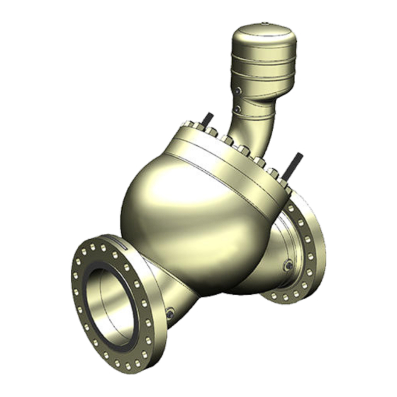
DANIEL
®
CONTROL VALVES
USER MANUAL
MODELS 762, 763, 765, 766 AND 767
NPS 2 THROUGH 16 / CLASS 150-600
Decades Proven. Field Chosen.
™
OCTOBER 2022
Table of
Contents
Previous
Page
Next
Page
1
2
3
4
5
Advertisement
Table of Contents
Need help?
Do you have a question about the 762 and is the answer not in the manual?
Ask a question
Questions and answers
Related Manuals for DANIEL 762
Control Unit DANIEL 700 User Manual
Nps 2 through 16 / class 150-600 (58 pages)
Control Unit DANIEL V707 User Manual
Spring loaded back pressure valve nps 2 through 4 / class 150-600 (48 pages)
Control Unit DANIEL 765 User Manual
(103 pages)
Control Unit DANIEL 766 User Manual
(103 pages)
Control Unit DANIEL 767 User Manual
(103 pages)
This manual is also suitable for:
763
765
766
767
Table of Contents
Print
Rename the bookmark
Delete bookmark?
Delete from my manuals?
Login
Sign In
OR
Sign in with Facebook
Sign in with Google
Upload manual
Upload from disk
Upload from URL


Need help?
Do you have a question about the 762 and is the answer not in the manual?
Questions and answers