Life Fitness CLUB Series Assembly Instructions Manual
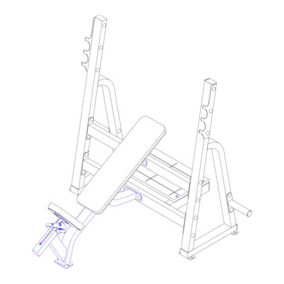
Olympic incline bench
Hide thumbs
Also See for CLUB Series:
- User manual (48 pages) ,
- Service manual (35 pages) ,
- Operation manual (26 pages)
Advertisement
Quick Links
Advertisement

Subscribe to Our Youtube Channel
Related Manuals for Life Fitness CLUB Series


Summary of Contents for Life Fitness CLUB Series
- Page 1 CLUB SERIES OLYMPIC INCLINE BENCH ASSEMBLY INSTRUCTIONS Part # 72xxxx Revision:5/02/02 Rev A.
- Page 2 PARTS LIST PART # DESCRIPTION PART # DESCRIPTION UPRIGHT 3102922 3/8 X 2-3/4” BOLT SPOTTER SUPPORT 3102905 3/8 X 3-3/4” BOLT CROSS BRACE 3102807 3/8” LOW HEIGHT LOCK NUT BENCH FRAME 3102514 3/8” SAE WASHER FOOT PLATFORM 6866701 3/8” RH WASHER BACK PAD 6866601 BLACK RH CAP...
- Page 3 10 3/8 X 1-1/4” BOLT 3/8” LOW HEIGHT LOCK 11 3/8 X 2-3/4” BOLT 12 3/8 X 3-3/4” BOLT 3/8” SAE WASHER 18 3/8 X 4-1/4” BUTTON HEAD BOLT RH CAP WASHER (BLACK/WHITE/PLATINUM)
- Page 4 FIGURE 1 3/8 X 3-3/4” 12 STEP 1: • LOOSELY assemble the two UPRIGHTS (1) to the SPOTTER SUPPORT (2) and the CROSS BRACE (3) using sixteen RH CAPS (17), eight 3/8 X 3-3/4” BOLTS (12), sixteen 3/8” SAE WASHERS (14), sixteen 3/8” RH WASHERS (15) and eight 3/8” LOW HEIGHT LOCK NUTS (13) as shown in FIGURE 1.
- Page 5 FIGURE 2 11 3/8 X 2-3/4” STEP 2: • LOOSELY assemble the BNECH FRAME (4) to the SPOTTER SUPPORT (2) and CROSS BRACE (3) using eight RH CAPS (17), four 3/8 X 2-3/4” BOLTS (11), eight 3/8” SAE WASHERS (14), eight 3/8” RH WASHERS (15) and four 3/8” LOW HEIGHT LOCK NUTS (13) as shown in FIGURE 2.
- Page 6 FIGURE 3 18 3/8 X 4-1/4” STEP 3: • SECURELY assemble the FOOT PLATFORM (5) to the SPOTTER SUPPORT (2) using four 3/8 X 4-1/4” BUTTON HEAD BOLTS (18), four RH CAPS (17). four 3/8” SAE WASHERS (14), four 3/8” RH WASHERS (15) and four 3/8” LOW HEIGHT LOCK NUTS (13) as shown in FIGURE 3.
- Page 7 FIGURE 4 11 3/8 X 2-3/4” 3/8 X 1-1/4” 10 STEP 4: • SECURELY assemble the BACK PAD (6) to the BENCH FRAME (4) using two RH CAPS (17), two 3/8 X 2-3/4” BOLTS (11) and two 3/8” RH WASHERS (15) as shown in FIGURE 4. •...
- Page 8 FIGURE 5 12 3/8 X 3-3/4” STEP 5: • SECURELY assemble the two BAR SUPPORT RACKS (8) to the UPRIGHTS (1) using six BLACK RH CAPS (16), six RH CAPS (17), six 3/8 X 3-3/4” BOLTS (12), twelve 3/8” SAE WASHERS (14), twelve 3/8” RH WASHERS (15) and six 3/8” LOW HEIGHT LOCK NUTS (13) as shown in FIGURE 5.
- Page 9 FIGURE 6 12 3/8 X 3-3/4” STEP 6: • SECURELY assemble the two WEIGHT HORNS (9) to the UPRIGHTS (1) using four BLACK RH CAPS(16), four RH CAPS (17), four 3/8 X 3-3/4” BOLTS (12), eight 3/8” SAE WASHERS (14), eight 3/8” RH WASHERS (15) and four 3/8” LOW HEIGHT LOCK NUTS (13) as shown in FIGURE 6.
-
Page 10: Warranty Information
CAUTION-PLEASE READ There is a risk assumed by individuals who use this type of equipment. To minimize risk, please follow these rules: 1. Inspect equipment daily. Tighten all loose connections and replace worn parts immediately. Failure to do so may result in serious injury. 2.
Need help?
Do you have a question about the CLUB Series and is the answer not in the manual?
Questions and answers