
Related Manuals for Kistler 6239A Series


Summary of Contents for Kistler 6239A Series
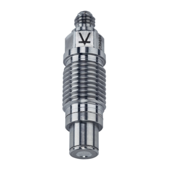
- Page 1 Instruction manual Piezoelectric Pressure Sensor Type 6239A… Tangential shot shell pressure sensor 6239A_002-833e-06.21...
- Page 2 Instruction manual Piezoelectric Pressure Sensor Type 6239A… Tangential shot shell pressure sensor 6239A_002-833e-03.19...
- Page 3 ForewordIntroduction...
- Page 5 Information in this document is subject to change without notice. Kistler reserves the right to change or improve its products and make changes in the content without obligation to notify any person or organization of such changes or improvements.
-
Page 6: Table Of Contents
Piezoelectric Pressure Sensor Type 6239A… Content Introduction ..........................3 Important information ......................... 4 Warranty ..........................4 Disposal instructions for electrical and electronic equipment ..........4 Sensor ............................5 General functional description..................... 5 Measuring chain ........................6 Installation and operation ......................8 Mounting configurations ...................... -
Page 7: Introduction
It will help you with the installation, maintenance, and use of this product. To the extent permitted by law, Kistler does not accept any liability if this instruction manual is not followed or products other than those listed under Accessories are used. -
Page 8: Important Information
Piezoelectric Pressure Sensor Type 6239A… Important information Warranty The equipment supplied by Kistler Instrumente AG Winterthur is covered by a warranty against faulty material and workmanship. This warranty extends 12 months from delivery date. When submitting warranty claims, the items of equipment... -
Page 9: Sensor
Sensor Sensor General functional description Piezoelectric pressure sensor Type 6239A… is suitable for tangential shot shell pressure measurements. Also general high pressure measurements up to 1 500 bar can be performed with this sensor. The shoulder sealing design allows a flush or recessed mounting configuration. Sensor Type 6239A…... -
Page 10: Measuring Chain
0 ... 1500 bar or 0 ... 150 bar on the charge amplifier. High-insulation, low-noise cable It is advisable to exclusively use Kistler cables. For cables from other manufacturers, compatibility with the sensor connector is not guaranteed and can result in poor signal transmission. - Page 11 Connectors on the cable and sensor can be cleaned with cleaning spray Type 1003. Charge amplifiers Types 5015, 5018, 5165A and other Kistler laboratory type charge amplifiers allow the required measuring range to be freely adjusted. Static...
-
Page 12: Installation And Operation
Piezoelectric Pressure Sensor Type 6239A… Installation and operation 4.1 Mounting configurations 4.1.1 Tangential mounting The flush mounting configuration is intended for tangential shot shell pressure measurement. There is no dead space between the sensor diaphragm and test chamber. sensor diaphragm tangentially aligned to the shot shell or the test chamber. -
Page 13: Mounting Bore Preparation
Installation and operation Mounting bore preparation 4.2.1 Dimensions The bore depth must be sufficiently long to allow thread engagement over the full length of the sensor. Installing the sensor for tangential pressure measurement (flush mounting) requires a depth (barrel wall thickness) of max. -
Page 14: Machining
Piezoelectric Pressure Sensor Type 6239A… Fig. 8: Recess mounted situation for Type Fig. 9: Recess mounted situation for Type 6239ABA (UNF 3/8-24 thread) 6239AAA (M10 thread) 4.2.2 Machining Most important bore parameters: Perpendicularity of M10x1 or 3/8-24 UNF to sealing surface The thread must be positioned exactly concentrically to the bore. - Page 15 Installation and operation 2. Counterboring Flush mounting Tool Type Depth Ø 9 / 8.5 mm drill for M10 / UNF 12 mm Ø 6.25 mm drill 18 mm (through wall thickness) Recessed mounting Tool Type Depth Ø 9 / 8.5 mm drill for M10 / UNF 12 mm Ø...
-
Page 16: Quality Of Mounting Bore
Piezoelectric Pressure Sensor Type 6239A… 4.2.3 Quality of mounting bore 4.2.3.1 Faulty sealing surface An uneven or concave sealing surface (Fig. 10) will impede a proper sealing function. If an excessive tightening torque is applied repeatedly, the sensor may also dig into the sealing surface preventing uniform pressure distribution over that surface. - Page 17 Installation and operation Fig. 12: Surface finishing tool Type 1300A46A1 (M10x1 thread) or 1300A25A1 (3/8-24 UNF thread) Fill the grooves of the cutting surfaces with special lubricating grease Type 1063 (supplied). The grease picks up the chips, preventing them from becoming jammed between cutter and sealing surface.
- Page 18 Piezoelectric Pressure Sensor Type 6239A… Adjust the friction force by tightening or loosening with the tubular socket wrench, so that the reamer can be easily turned by hand. Ream sealing surface: Rotate the red handle in counter-clockwise direction for 5 revolutions. ...
-
Page 19: Sensor Installation And Removal
Installation and operation Sensor installation and removal 4.3.1 Installation During the installation of sensor Type 6239A... the sealing ring 1100A105 has two functions. First, it seals and avoids gas evasion and pressure loss through the thread. Second, for tangential shot shell pressure measurements the rings are used to adjust the distance of the sensor from the cartridge (see section 6.1.1). - Page 20 Piezoelectric Pressure Sensor Type 6239A… Fig. 18: Insert the sealing ring. For every additional sealing ring, two additional dots of grease must be applied. Fig. 19: Apply grease to the sensor thread to facilitate insertion. Check the mounting bore for any remaining sealing rings from the previous installation.
-
Page 21: Tightening
Tightening torques >15 N·m may damage the sensor (plastic deformation and mushrooming of the shoulder part). Kistler recommends dial type torque wrenches such as Kistler Type 1371B to prevent application of excessive torque. Fig. 21: Torque wrench Type 1371B can be used to apply a precise mounting torque. -
Page 22: Cabling
Piezoelectric Pressure Sensor Type 6239A… replaced. If the leakage persists, inspect the sensor shoulder and mounting cavity for damaged sections. 4.3.3 Cabling Cables should be routed to avoid tension, kinking, and sharp bends, particularly at the connectors. Restrain cables by tying, taping or clamping in highly vibrating environments so as to avoid mechanical damage. -
Page 23: Maintenance And Calibration
Fine cleaning: for fine cleaning it is recommended to dip the sensor in a cleaning agent based on mineral oil (e.g. petroleum ether, petrol), wipe it with a paper towel and apply Kistler cleaning spray Type 1003. Repairs shall only be conducted by Kistler. 5.1.2 Connectors... - Page 24 However, never use air-blast to clean the connectors. It will unavoidably deposit a film of water vapor. Instead, Kistler strongly recommends the use of cleaning spray Type 1003. Please contact your local sales center, should drift or measurement of low insulation persist after cleaning all connectors.
-
Page 25: Recalibration
10 % FS using stepwise dead weight testing as well as continuous pressure ramps. The sensitivity is provided on an individual calibration certificate. detailed recommendations regarding periodic recalibration, please refer to the Kistler brochure ‘Calibration and Dynamic Verification of Pressure Sensors for Ballistic Applications’. 6239A_002-833e-03.19 Page 21... -
Page 26: Various Measuring Arrangements
For this purpose Kistler offers the dial gauges 1300A48A1 (M10x1 thread) and 1300A48A2 (3/8-24 UNF thread). 6.1.1 Distance adjustment using dial gauge Type 1300A48A1 or Type 1300A48A2 6.1.1.1... - Page 27 Various measuring arrangements Fig. 24 The dial gauge is inserted into the sensor mounting bore. The adapter front aligns with the sealing surface of the mounting bore, and the pin touches the dummy cartridge. 6239A_002-833e-03.19 Page 23...
- Page 28 Piezoelectric Pressure Sensor Type 6239A… As a first step the dial gauge always needs to be zeroed. For this procedure, attach the zeroing adapter to the dial gauge. The pin retracts and evenly aligns with the adapter front. Then press the red button to zero the gauge.
-
Page 29: Calculating The Number Of Spacer Rings
Various measuring arrangements 6.1.1.2 Calculating the number of spacer rings With the dial gauge the distance between the sealing surface of the sensor and the dummy cartridge is measured. This distance D should be read from the display, as explained in the previous paragraph, and noted down. -
Page 30: General High Pressure Measurement
Piezoelectric Pressure Sensor Type 6239A… General high pressure measurement For general high pressure applications, the recess mounted setting has an advantage over the flush mounted setup, as the sensor membrane is protected from the effect of high flash temperature and particle hit, due to the passage hole. -
Page 31: Influence Of Long Measuring Bore
Various measuring arrangements 6.3 Influence of long measuring bore A passage (measuring) hole length of 3 ... 5 mm is ideal, since no disturbing gas vibrations occur in a hole of this length. Long measuring bores act like a low-pass filter. Low frequencies are measured free of error.
Need help?
Do you have a question about the 6239A Series and is the answer not in the manual?
Questions and answers